FPQA-C: A Compilation Framework for
Field Programmable Qubit Array
Abstract
The neutral atom array has gained prominence in quantum computing for its scalability and operation fidelity. Previous works focus on fixed atom arrays (FAA) that necessitate extensive SWAP operations for long-range interactions. This work explores a novel architecture known as field programmable qubit array (FPQA), which uniquely allows for coherent atom movements during circuit execution and significantly reduces the cost of long-range interactions. However, the atom movements have multiple hardware constraints, e.g. overlap or position swap of two atom rows/columns are not allowed, making movement scheduling very challenging.
In this work, we introduce FPQA-C, a compilation framework tailored for qubit mapping, atom movement, and gate scheduling of FPQA. It contains a qubit-array mapper to decide the coarse-grained mapping of qubit to arrays, leveraging MAX k-Cut on a constructed gate frequency graph to minimize SWAP overhead. Subsequently, a qubit-atom mapper determines the fine-grained mapping of qubits to specific atoms in the array, and considers load balance to prevent hardware constraint violations. We further propose a high-parallelism router that iteratively identifies parallelizable 2Q gates and decide the atom movements and gate executions, thus improving the parallelism. Besides, for fault-tolerant computing with FPQA, we provide comprehensive simulations evaluating logical error rates, execution times, physical qubit requirements, code distances, and bandwidth.
We rigorously assess FPQA-C across 20+ diverse benchmarks, including generic circuits (arbitrary, QASMBench, SupermarQ), Quantum Simulation, and QAOA circuits. FPQA-C consistently outperforms the IBM Superconducting, FAA with long-range gates, FAA with rectangular and triangular topologies, achieving 2Q gate reductions by factors of 5.3, 3.2, 3.4, and 2.6, and circuit depth reductions by factors of 3.6, 3.2, 3.1, and 2.2, respectively.
I Introduction
The landscape in the field of Quantum Computing (QC) is rapidly evolving. Recent developments have introduced superconducting systems with as many as 433 qubits [38, 39, 74, 41, 35, 42]. Parallel advancements in neutral atom arrays have also been striking: Ebadi et al.[23] demonstrated up to 289 qubits, while QuEra has offered a 256-qubit system on AWS [72, 99, 26]. This momentum has catalyzed the architecture community to focus on compiler development for these platforms that map and route the qubits [47, 44, 68, 78, 22, 1, 29, 36]. Baker et al.[6] pioneered the first compiler framework tailored for neutral atom arrays, adapting qubit mapping strategies from superconducting systems and accommodating the unique advantages and constraints of neutral atoms, such as long-range interaction zones and sporadic atom loss. Building on this, Patel et al. (Geyser)[70] proposed enhancing the system’s efficiency by re-synthesizing circuits into 3Q blocks to utilize native multi-qubit operations.
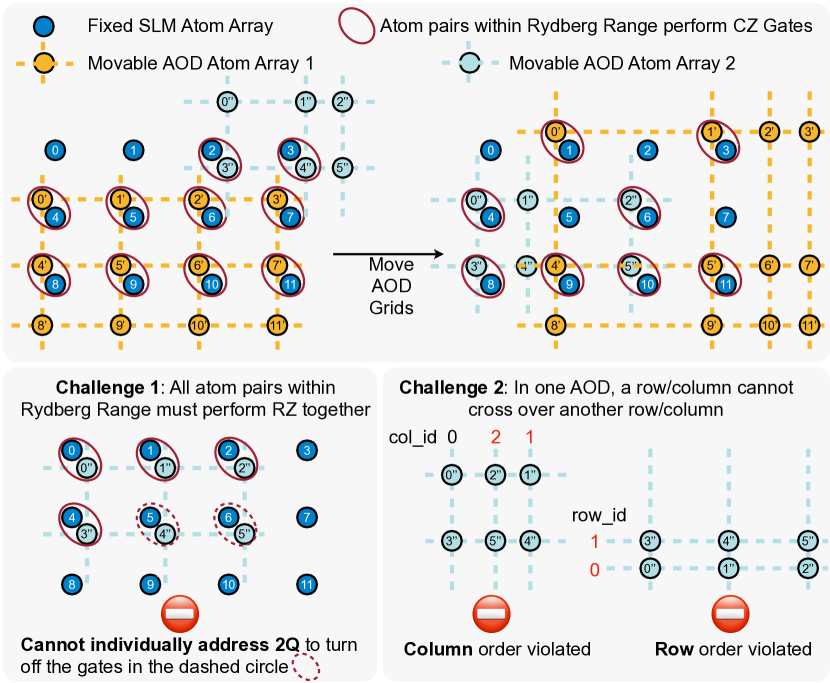
While much of the existing research has centered on fixed atom arrays (FAA), a more versatile architecture has surfaced: the field programmable qubit array (FPQA), featuring both fixed and dynamically movable atoms [11, 80]. As depicted in Fig. 1, this introduces a dynamic coupling map between qubits, induced by the current atom locations. The flexible reconfigurability minimizes overhead and draws a parallel to the adaptability seen in Field-Programmable Gate Arrays (FPGAs). The atom mobility also makes efficient long-range interaction possible, because we can directly move the atoms instead of performing extensive SWAP gates.
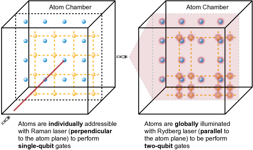
FPQA incorporates a fixed atom array (SLM) and multiple movable arrays (AOD). Atoms in the AOD reside at the intersections of a 2D grid, manipulated via laser-controlled row and column positions. As shown in Fig. 2, 1Q gates are laser-addressable from the front, while 2Q gates are executed by moving atom pairs to adjacent locations and activating them with a side-illuminating Rydberg laser. Due to the global nature of Rydberg illumination, all closely-located atom pairs undergo compulsory 2Q gates. This brings high parallelism execution but requires careful movement scheduling to avoid unwanted 2Q gates. Tan et al.[80] presented the first FPQA compiler, leveraging a satisfactory modulo theory (SMT) solver for qubit mapping and routing. Despite its ingenuity, the method faces scalability challenges due to the exponential time complexity of SMT solving. Furthermore, it neglects the detrimental impact of atom transfers between SLM and AOD, a critical operation results in severe atom loss [23]. This oversight becomes significant in iterative algorithms like QAOA or Trotterized quantum simulations, leading to potential circuit failures. Another concurrent work [96] leverage AOD atoms as ancilla qubits to reduce depth of the circuits but introduces 2Q gate overhead.
In this paper, we introduce a comprehensive, scalable compilation framework for FPQA, accounting for errors due to atom movements and transfers. Our approach conceptualizes the hardware as a complete multipartite coupling graph with conditional edge sets, capturing all potential qubit couplings based on movable array positions. This framework addresses two key challenges: (1) the absence of individual addressability for 2Q gates, requiring that all edges in a given edge set must host legitimate 2Q gates when atoms are within the Rydberg interaction range, and (2) the AOD arrays’ immutable row and column order, which yields mutually exclusive edges sets whose gates cannot be executed in parallel. These constraints necessitate innovative solutions for effective qubit mapping, atom movement, and gate scheduling.
To efficiently address the compilation challenges, we employ a two-tiered hierarchical mapping strategy. Firstly, the coarse-grained qubit-array mapper decides assignments of qubits to atom arrays. The 2Q gates between atoms from two arrays can be executed with atom movement, while intra-array 2Q gates cannot be directly executed and require additional SWAPs. Therefore, the mapper tries to maximize the inter-array gates by formulating the problem as a MAX k-Cut (k is the number of arrays) of a constructed gate frequency graph and solving it with an efficient heuristic. Subsequently, at a more granular level, we propose a qubit-atom mapper that positions the qubits to specific atoms in the array. The SLM qubit-atom mapper considers the load balance among rows and columns to minimize the risk of violating the hardware constraints on order-preserving of AOD rows and columns, and no-overlapping requirements. Then, the AOD qubit-atom mapper strategically maps qubit pairs with frequent 2Q gates to consistent locations across different arrays to increase parallelism. After completing this dual-level mapping, our high-parallelism AOD atom router is activated. In one iteration, it identifies a front layer of non-dependent gates in the transpiled circuit and selects a subset of these gates that satisfies all the hardware constraints. Then it performs the movements of AOD rows and columns, and illuminates the lasers for gate execution. The router works iteratively until the circuit finishes.
We extensively evaluate FPQA-C on 20+ benchmarks of generic circuits (arbitrary, QASMBench, and SupermarQ circuits), Quantum Simulation, and QAOA circuits with a number of qubits from 5 to 100 and a number of 2Q gates from to . We simulate the circuit fidelity under realistic parameters while comprehensively modeling four aspects of movement overhead, including heating, cooling overhead, decoherence, and atom loss. On average, FPQA-C achieves 5.3, 3.2, 3.4, and 2.6 in 2Q gate reduction, 3.6, 3.2, 3.1, and 2.2 in depth reduction over IBM Superconducting, FAA with long rang gate [6], FAA with rectangular topology, and FAA with triangular topology. FPQA-C is 1000 faster than a solver based [80] compiler with similar fidelity. It also reduces the number of pulses by up to 5.8 over Geyser [70]. For surface code on FPQA, we simulate the logical error rate, bandwidth requirements under different code distances, and physical error rates with realistic noise modeling. We further estimate the execution time and physical qubit requirement under different overall error budgets and code distances to run the benchmarks above.
Our contributions are summarized as follows:
We introduce the architecture and constraints of emerging FPQA device and abstract the hardware model as a complete multipartite coupling graph with conditional edge sets.
We identify two critical compilation challenges and propose corresponding mapping and 2Q gate scheduling strategies to reduce 2Q gate overhead and increase parallelism.
We also explore the implementation of surface code on FPQA and the scheduling of syndrome extraction.
Our framework outperforms the superconducting and fixed atom array baselines in terms of 2Q gate count, circuit depth, and fidelity. Compared with the solver-based compiler, it has orders of magnitude faster compilation speed while having similar circuit fidelity.
II FPQA Background and Related Work
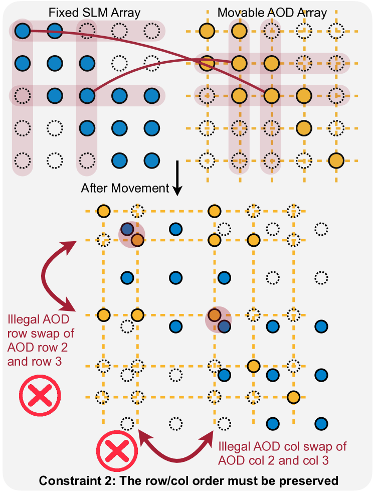
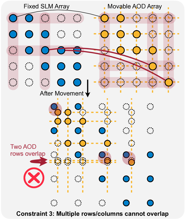
FPQA Qubit Movement. In FPQA, atoms are held in two kinds of traps as illustrated in Fig.1: fixed traps generated by a spatial light modulator (SLM) and movable traps created by crossed 2D acousto-optic deflectors (AODs). Each 2D AOD is composed of two intersecting 1D AODs, capturing atoms at the points of intersection. The system allows for manipulation of the X/Y coordinates of AOD columns/rows for aligned qubit movements. Notably, within the same AOD set, a column/row is restricted from crossing another (Fig.1 Challenge 2). However, columns/rows from different AOD sets can intersect. While the figure depicts two AOD sets, control over additional sets has been experimentally validated [30].
FPQA Gates. High-fidelity, individually addressable 1Q gates are induced by a Raman laser (Fig.2 left) [11, 45, 30]. 2Q entangling gates are achieved through the Rydberg blockade mechanism [40]. When two atoms are within the Rydberg range and illuminated by a Rydberg laser, a controlled -rotation is induced (Fig.2 right). We need to move two qubits within of each other for 2Q gates, or to separate them by when no gate is performed (Fig.1 Challenge 1).
Pros & Cons of Neutral Atom Arrays in General. Neutral atoms enjoy the same benefits as other natural qubits, e.g., ions, compared to fabricated qubits, e.g., superconductors: high-fidelity gates, ease of calibration, and virtually limitless source. Compared to electrical traps used by ions, the optical traps for neutral atoms are much easier to be 2D and thus scale to much larger sizes, e.g., 1020 SLM traps demonstrated in [24]. In the long run, the scalability of FPQAs can still be challenging at a-few-thousand-qubits scale because they are built from quantum optics experimental apparatus not initially designed for large-scale quantum computing. However, this limitation is comparative, as other platforms lag behind in scaling so far. Companies like QuEra and PASQAL have begun developing hardware with scalability in focus.
Pros & Cons of FPQA vs FAA. In FAA [30, 6, 70, 75, 7], fixed SLMs restrict qubit connectivity, requiring an additional AOD grid to modulate Rydberg interactions between selected adjacent pairs. This limits scalability, as twice as many SLMs and a similarly sized modulating AOD are needed compared to FPQA. This also compromises CZ fidelity; e.g., 92.5% in FAA [30] versus 97.5% in FPQA [11]. FAA needs SWAP gates (3 CZs) to route the qubits for 2Q gates. In contrast, FPQA’s AOD movements are high-fidelity, limited primarily by coherence time. Ref. [11] estimates that with only of coherence time lost, an AOD array could traverse a region hosting qubits. A drawback of atom movement and transfer is the risk of atom loss, jeopardizing the integrity of the entire quantum circuit. Thus, a careful comparison of these two routing methods is required, as we shall see in this paper.
Application-Specific Compilation. We contrast FPQA-C with three existing application-specific compilers: ZZ [2, 3, 4], 2QAN [44], and Paulihedral [51]. ZZ focuses on commutation of ZZ gates in QAOA; our approach generalizes this by avoiding suboptimal layering of ZZ gates. 2QAN minimizes SWAPs by absorbing them into existing 2Q unitaries, a technique less relevant for FPQA, which employs atom movement for routing instead. Paulihedral presents two strategies: 1) Optimizing Pauli term order to reduce circuit depth, a technique orthogonal to our work and applicable to pre-routing; 2) Tailoring each Pauli term for limited-connectivity NISQ hardware, a method less applicable to FPQA.
III FPQA-C Compilation Framework
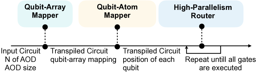
The overall compilation flow is shown in Figure 3. Our compiler contains a qubit-array mapper to determine which array each qubit should be placed in, and a qubit-atom mapper to decide the specific position of each qubit inside the mapped array. After deciding all qubit positions, we also design a high-parallelism router to generate the movements and gate schedules of AOD array rows and columns, respecting the hardware constraints and maximizing the parallelism.
III-A Qubit-Array Mapper
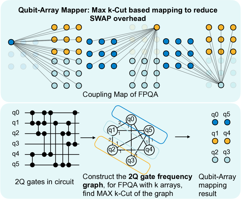
As shown in Fig. 4, the FPQA features one static SLM array and multiple dynamic AOD arrays, represented by different colors in the Fig. 4 top. In the SLM array, qubits are fixed and atom pairs in SLM will never fall within the Rydberg radius, precluding intra-array 2Q gates. For atom pairs in the same AOD, our compiler also avoids intra-AOD 2Q gates due to the risk of non-deterministic behavior and atom loss [11]. Consequently, 2Q gates can only be performed between two arrays. Since there is only one fixed SLM array, at least one array of the two will be a movable AOD array and thus the gate can be executed via atom movement. This results in a complete multipartite graph for feasible 2Q gate operations. Thanks to the symmetry, the atoms in the same array are equivalent from the coupling map perspective. Therefore, we tackle the mapping problem hierarchically: firstly, deciding which array a qubit should be mapped to, and secondly, determining the specific position for the qubit in that array.
Ideally, if all gates in a circuit involve qubits in different arrays, there will be no SWAP overhead. To this end, FPQA-C tries to find a mapping to maximize the inter-array gates and thus reduce SWAP overhead. This goal can be approached with a 2Q gate frequency graph as shown in Fig. 4 bottom. In the graph, each vertex represents a qubit and an edge indicates there existing a gate between two qubits. The edge weights are determined by the frequency of 2-qubit gates between the qubit pairs. More gates between a qubit pair will result in a large edge weight. Then, finding the mapping that allows the most directly executable inter-array 2Q gates is translated to a MAX k-Cut of the gate frequency graph, where the graph is divided into k partitions, corresponding to k arrays in FPQA, aiming to maximize the summation of edge weights crossing different partitions. Although this problem is NP-hard, we adopt a straightforward greedy algorithm that yields an approximation of [16], i.e., the cut given by the greedy algorithm is at least times the optimal solution. The greedy algorithm decides the partition assignment of each vertex one by one while ensuring that each vertex can maximize the cut between partitions of already assigned vertices. The algorithm is outlined in Alg. 1.
For specific edge weight calculation, each gate between a qubit pair will contribute a weight that exponentially decreases according to how many layers the gate is from the first layer and controlled by a factor . We add decay because, for most cases, there will still be intra-partition edges after finding the MAX k-Cut. Therefore, some SWAP insertions are necessary to execute that gate. Since the SWAP will change the array mapping, it is better to consider the first several layers instead of all layers together when we decide on the initial mapping. Therefore, we set a decay factor to emphasize more on front layers while preserving some forecasting capability. After finding the initial qubit-array mappings, we leverage the default SABRE [48] in Qiskit to insert SWAP gates and pass the mapping and transpiled circuit to the qubit-atom mapper.
III-B Qubit-Atom Mapper
FPQA-C further decides the fine-grained position of each qubit in each array. This step does not impact the SWAP overhead. Instead, it essentially focuses on selecting optimal atom positions in the array to minimize circuit depth. It is crucial to note that once atoms are positioned, the absolute positions of SLM atoms and the relative positions of AOD atoms are immutable during circuit execution. Sub-optimal mapping can diminish opportunities for parallel gate execution, thus elongating the circuit depth. In the worst-case scenario, all 2Q gates need to be executed sequentially, even without circuit-level dependencies. Therefore, the primary goal of our qubit-to-atom mapping is to maximize the parallel gate executions. To achieve this, we perform qubit-atom mapping in two steps: firstly, map all SLM qubits, and secondly, map all AOD qubits.
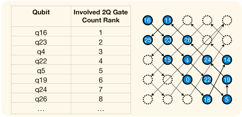
First, it is crucial for qubit-atom mapping of SLM qubits following the design principle of load balance between rows/columns. Specifically, we need to balance the number of atoms across rows because most qubits concentrating in a few rows will create more conflicts within the same row. Column load balance is similar. To this end, we propose the load balance SLM mapping strategy, as illustrated in Fig. 5. We first sort the qubits in descending order based on their involved 2Q gate count. Then, we map the qubits to atoms with a topological order starting from the upper-left corner, prioritizing filling the diagonal first and subsequently forming a spiral trajectory. This will ensure that the row-wise/column-wise sum of involved 2Q gates of qubits is balanced across all rows/columns. The load balance can, in return, maximally avoid the violations of the constraint1 on unwanted gates (Fig. 8) and constraint3 that rows/columns cannot overlap as illustrated (Fig. 10). Intuitively, two atoms from a near-diagonal region will have a larger chance to differ in row and column index.
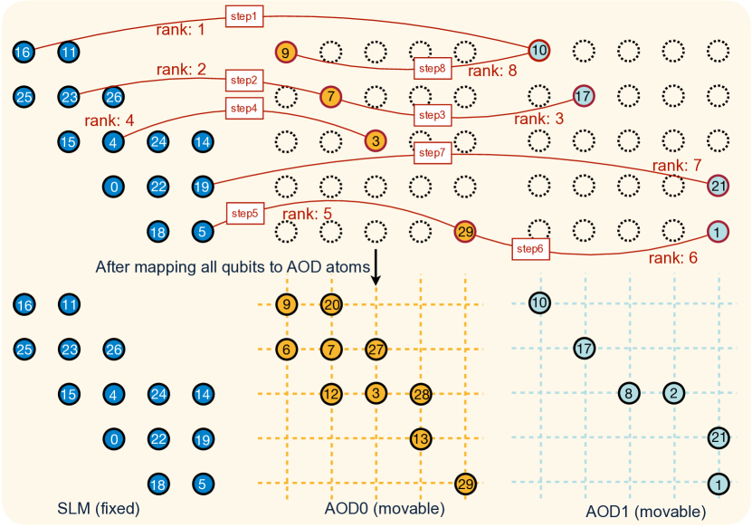
Second, we need to map AOD qubits. The design principle for AOD mapping is position alignment for frequent qubit pairs. Specifically, we propose alignment AOD mapping to make sure that the pairs of atoms of the same positions in two arrays will have highly frequency 2Q gates so that we naturally enable higher parallelism if we move and align two arrays. We first sort the frequency of qubit pairs with 2Q gates; then, the frequent pairs will be mapped to the same spatial location in two arrays as the example shown in Fig. 6. The SLM qubits atom mapping is already determined. The “rank” is determined by 2Q gate frequency, in a decreasing order. The q16 and q10 have the highest frequency, so we map q10 to the same top left corner as q16 in the SLM array. Similarly, for the second rank gate between q23 and q7, we map q7 to the same row2 column2 position in the yellow AOD0 as q23 in SLM. This mapping strategy will avoid the constraint 2 violation on row/col orders (Fig. 9) because the high-frequency gates will have small relative displacement.
III-C High-Parallelism AOD Router
With the specific qubit-atom mappings and the transpiled circuit, we propose a router for AOD atom movements and gate scheduling. The router’s responsibility is to generate the instructions on the movement of rows and columns of all AODs and decide when to turn on the lasers to perform gates. Meanwhile, it must respect all the hardware constraints during movements and optimize for high parallelism.
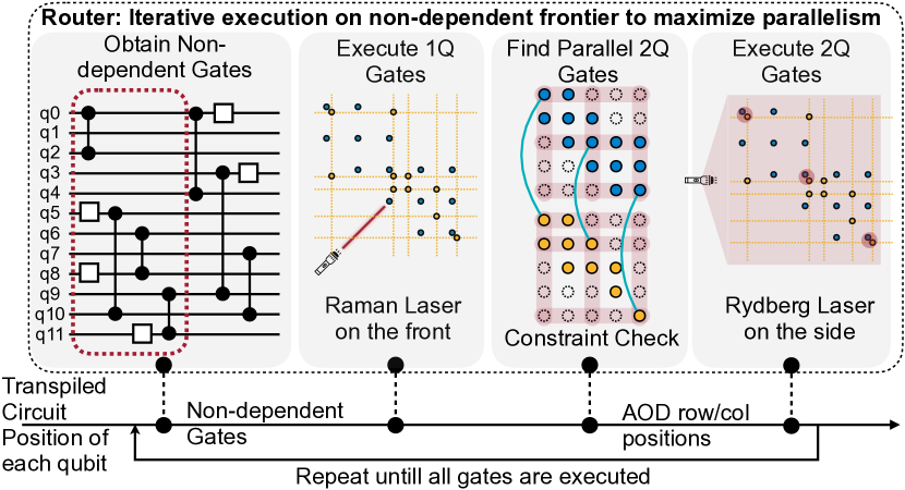
The pipeline is depicted in Fig. 7. The router first identifies non-dependent “frontier gates” from a Directed Acyclic Graph (DAG) circuit representation. Then, it executes all single-qubit gates by illuminating the Raman lasers. Although 2Q gates don’t have circuit-level dependencies and could theoretically be executed in parallel, moving them all to the corresponding atom may violate the hardware constraints. Therefore, the router greedily finds maximally legal parallel 2Q gates. Starting with a single gate, the router incrementally adds gates to the set, assessing three hardware constraints. If violated, the 2Q gate will not be added to the set but pushed back to the circuit DAG. After finding the hardware legal parallel 2Q gate set, the router will move AOD rows and columns to the target positions and turn on the Rydberg laser to perform 2Q gates. This router runs iteratively until the entire circuit finishes.
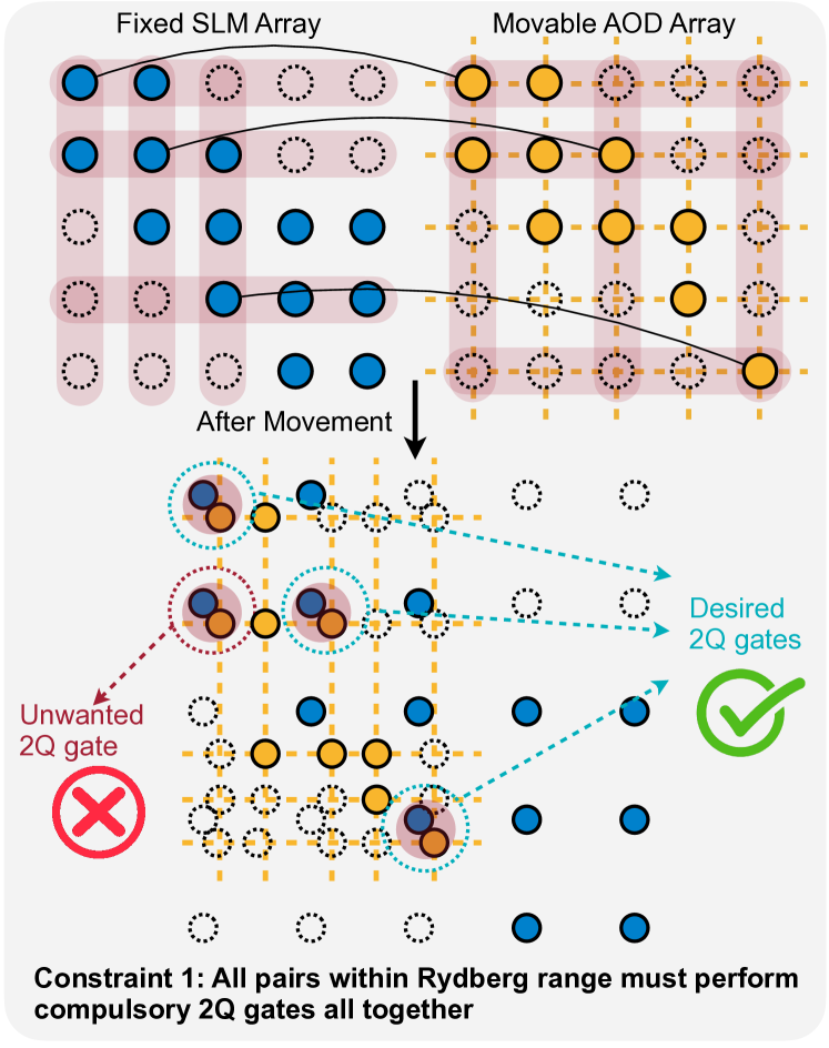
The first hardware constraint is that all pairs within Rydberg range must perform gates all together as in Fig. 8. In the figure’s top part, three black connection lines indicate the valid gates in the circuit. If we perform the movement to perform those gates simultaneously, as in the bottom part, we will introduce an unwanted gate marked in red. Therefore, this set of gates cannot be executed in parallel. The second hardware constraint is shown in Fig. 9: the row order and column order of AOD arrays must be preserved, i.e., there cannot be a position swap of two rows/columns. In the figure, we show that to execute two 2Q gates annotated by two red lines on the top, we have to swap row 2 and row 3 and swap column 2 and column 3, as illustrated in the bottom part. This is illegal and, thus, will not be accepted by the router. The third constraint is that AOD rows and columns cannot overlap as in Fig. 10. To finish the two gate pairs connected by red lines, AOD rows 4 and 5 must be moved to the same position and overlap, which is not allowable.
IV FPQA Fault-Tolerant Quantum Computing
With the atom array technology presented above, we can perform fault-tolerant quantum computing (FTQC) when the arrays are scaled to sufficiently large sizes and the error rates are suppressed below the threshold. A key advantage of FPQA is that qubits involved in different 2Q gates are separated sufficiently to block Rydberg interaction, which results in remarkably low crosstalk during the parallel execution of 2Q gates. [26]. As a result of this, there is no need to allocate qubit frequencies to prevent crowding in our approach, effectively circumventing a significant calibration challenge commonly encountered on superconducting platforms [5, 49]. We shall discuss FTQC on atom arrays based on surface code [28] in this section.
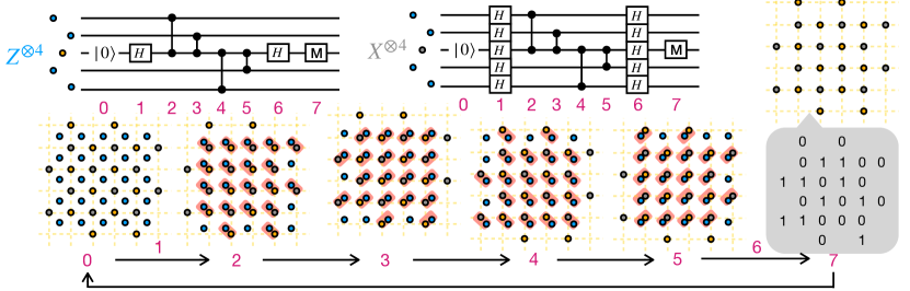
On FPQA, the surface code is a natural fit for error correction due to its 2D qubit layout, as depicted in Fig. 12. Data qubits reside in the SLM array, encoding quantum information, while measurement qubits in the AOD array perform stabilizer checks via 4-body or 2-body and parity measurements. The circuit for and checks are shown in the upper row of Fig. 12, and the corresponding FPQA operations are shown in the lower row. At stage 0, 1, and 6, 1Q gates are performed. (qubit reset can be performed by gates.) At stage 2 to 5, the 2Q gates are performed. Their order is carefully chosen so that no two 2Q gates can overlap on any qubit at any stage. The AOD array moves in a clock-wise manner during these stages to couple different pairs of data and measure qubits. At stage 7, the AOD is shifted to another region to perform measurements that yields a syndrome (bits in the callout). We repeat this syndrome extraction procedure round and round. Based on the syndromes measured at all rounds, we can decode the errors happened. These errors are not actively corrected immediately, but kept track of and accounted for in classical control software.
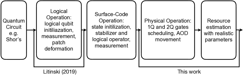
QEC only corrects errors or preserves information, so we need further operations to perform computation on top of QEC, which is the FTQC scheme. We opt for Litinski’s surface-code patch scheme [58] which is considered to be the state-of-the-art scheme for computation on surface code memory. The flow of compilation is shown in Fig. 11. Ref. [58] readily provides methods to decompose quantum circuits to protocols which are multi-body Pauli rotations with angle , multi-body Pauli parity measurements, and magic state distillation. These protocols are further decomposed into surface-code operations which are state initialization, stabilizer and logical operator measurement on the logical qubit level. We provides the FPQA implementation of stabilizer measurement in Fig. 12, which contains all the AOD movements we ever need because in all the other surface-code operations, a measure qubit only interact with its four neighbors as well. We additionally assume that the 1Q and 2Q gates are individually addressable. This is different from the global Rydberg setting previously, but has been demonstrated, e.g., by Ref. [30]. In such an implementation, additional AODs are used not to host any qubits but to selectively turn on the 2Q gates. The individual addressability of 2Q gates means that we can change the stabilizer each measure qubit gets in the middle of computation, i.e., we can choose not to perform 2Q gates between a measure qubit and one of its neighbors, so that this measure qubit checks other stabilizers instead of . For example, we do not apply the 2Q gates between data qubits and the half transparent measure qubits in Fig. 12. The ability to adjust stabilizers combined with the ability to apply , , gates on physical qubits ensure that we can perform the surface-code state initialization. For logical operator measurement, we can transfer the patch of data qubits representing the logical qubit to another AOD, move to the measure all the data qubits, and then place them back. All the rest is taken care of by the classical control software [58]. By now, we have translated all the surface-code operations to physical operations for FPQA. Given the cost of these operations, we calculate realistic parameters like duration of each operation, and then we can use FTQC resource estimator, e.g., Ref. [9], to project realistic spacetime cost of running a quantum circuit fault-tolerantly.
V Atom Movement Overhead
We characterize atomic motion overhead through four metrics, as formulated in Eq. 1: additional two-qubit (2Q) error due to heating, ; atom loss from heating, ; additional overhead due to cooling, ; and decoherence during the movement, .
| (1) |
Atom Heating. Atom movement causes heating and degrades 2Q gate fidelity, necessitating the computation of the “vibrational quantum number”, , for each atom. This quantity encapsulates an atom’s cumulative vibrational energy due to heating. Our framework tracks each atom’s based on motion history.
| (2) |
According to [11], heating’s fidelity impact is proportional to both 2Q gate infidelity, (), and , as described in Eq. 2. In interactions involving one AOD and one SLM atom, the of the AOD atom is considered; for AOD-AOD interactions, the values are summed.
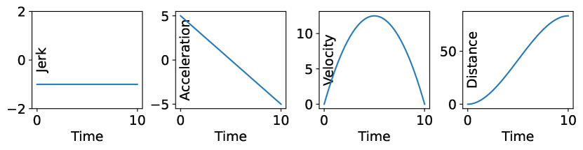
Ref. [11] propose a constant negative jerk (derivitive of acceleration) strategy as delineated in Figure 13 to minimize , resulting in a linearly decreasing acceleration and a parabolic velocity profile. The incremental change in for a single movement is:
| (3) |
where is the movement distance; is the zero-point size of the particle; is the Planck‘s constant; is the trap frequency and is the duration of this move. From this equation, we can obtain the insights: , indicating that a minor increase in allows a substantially greater before the heating error is too large, albeit at the cost of increased decoherence error. This trade-off is further analyzed in Section VI.
Here we analysis when doing atom movement is better than adding SWAPs. According to [11], nm, and can be between 40KHz and 80KHz. We use 80KHz. Movement time can be between 200s to 400s and we select 300s. Atom distance, the separation between atom rows and columns, needs to be larger than 6 times of Rydberg radius, which is . According to [11] Extended Fig.5d movement path and Extended Fig6.c in which the finite temperature (Doppler) error rate is 0.3%, we compute the in Eq. 2 as . With these parameters, movement-induced increases are calculated to be for a 1-hop movement, for 5 hops, and for 10 hops. In the experiments shown in Sec. VI, the cost for routing 2Q gates are around 2 the logical 2Q gates in FAA. Eq. 2 says the additional error incurred by heating is times the 2Q error. So, when , corresponding to fewer than 1000 gates, we expect better performance using FPQA atom movement since the overhead of movement will be less than that of additional SWAP gates.
Atom Loss. The heating and vibration also increase the atom loss probability. According to [11], the atom loss probability of moving and atom loss fidelity are:
| (4) |
| (5) |
where indicates the moved atoms in a movement. In [11], . When , ; when , ; when , . We see a fast improvement as reduces. Thus, we establish a threshold of 15 for cooling, beyond which the impact on atom loss is negligible.
| Parameter | 2Q fidelity | 1Q fidelity | 2Q gate T | 1Q gate T | Coherence T | ||
|---|---|---|---|---|---|---|---|
| Neu. Atom | 0.9975[11] | 0.99992[11] | 380ns[11] | 625ns[11] | 15s[11] | ||
| Supercon. | 0.9975 | 0.99992 | 480ns[37] | 35.2ns[37] | 801.2s[37] | ||
| Parameter | Atom distance | T per move | Atom transfer T | Atom loss P | |||
| Neu. Atom | 15m[11] | 300s[11] | s[11] | 0.0068[17] | 38nm[11] | 80kHz[11] | 0.109[11] |
Cooling Overhead. When any atom’s exceeds this threshold, cooling is initiated for the entire AOD array by swapping its quantum information with a pre-prepared, cooled AOD array initialized to the zero state. This information transfer requires two CZ gates for each atom, so the overhead is below. When threshold is 15, cooling is required every 100s of gates.
| (6) |
Decoherence. Finally, we model the decoherence due to the time overhead of moving atoms. , where is the moving time of stage , and is the number of qubits, including AOD and SLM used at stage . In assessing fidelity overheads, we juxtapose additional SWAPs in FAA with decoherence costs in FPQA. According to [11], the fidelity for a two-qubit (2Q) gate is , and . In the next section, our experiments show that the routing overhead for each 2Q gate in FAA is around two extra 2Q gates, reducing the overall fidelity by . For FPQA, the decoherence overhead for one additional 2Q gate in a 10-qubit circuit is . This overhead scales to and for 50- and 100-qubit circuits, respectively. Consequently, FPQA’s overhead is smaller than adding two 2Q gates in FAA. Remarkably, this advantage will persist in the forecasted future. Suppose both and are scaled by an order of magnitude to and , respectively. The revised overhead for 10, 50, and 100 qubits becomes , , and , while the routing overhead for FAA will be , maintaining FPQA’s relative benefit.
VI Evaluation
| Name | Type | Dataset | Num. | Num. | Num. | 2Q Gate | Degree | 24h Solver |
|---|---|---|---|---|---|---|---|---|
| Qubits | 2Q gates | 1Q gates | per Q | per Q | Timeout | |||
| HHL | Generic | QASMBench | 7 | 196 | 794 | 56.0 | 5.7 | timeout |
| Mermin-Bell | Generic | SupermarQ | 10 | 67 | 30 | 13.4 | 7.6 | timeout |
| QV | Generic | QASMBench | 32 | 1536 | 4096 | 96 | 19.7 | timeout |
| BV50 | Generic | QASMBench | 50 | 22 | 100 | 1.9 | 1.9 | timeout |
| BV70 | Generic | QASMBench | 70 | 36 | 417 | 1.9 | 1.9 | timeout |
| QSim-rand-20 | QSim | - | 20 | 180 | 275 | 18.0 | 4.2 | timeout |
| QSim-rand-40 | QSim | - | 40 | 380 | 567 | 19.0 | 5.7 | timeout |
| H2 | QSim | Molecule | 4 | 40 | 54 | 20.0 | 3.0 | solved |
| LiH | QSim | Molecule | 6 | 1134 | 1602 | 283.5 | 6.0 | timeout |
| QAOA-rand-10 | QAOA | - | 10 | 27 | 10 | 5.4 | 5.4 | timeout |
| QAOA-rand-20 | QAOA | - | 20 | 80 | 20 | 8.0 | 8.0 | timeout |
| QAOA-regu5-40 | QAOA | - | 40 | 100 | 40 | 5.0 | 5.0 | timeout |
| QAOA-regu6-100 | QAOA | - | 100 | 300 | 100 | 6.0 | 6.0 | timeout |
| Mermin-Bell | Generic | SupermarQ | 5 | 19 | 15 | 7.6 | 4.0 | solved |
| VQE | Generic | SupermarQ | 10 | 13 | 81 | 1.9 | 1.9 | solved |
| VQE | Generic | SupermarQ | 20 | 65 | 101 | 13.0 | 2.6 | solved |
| Adder | Generic | QASMBench | 10 | 9 | 40 | 1.8 | 1.8 | solved |
| BV | Generic | QASMBench | 14 | 19 | 80 | 1.9 | 1.9 | solved |
| QSim-rand-5 | QSim | - | 5 | 20 | 29 | 8.0 | 2.4 | solved |
| QSim-rand-10 | QSim | - | 10 | 80 | 122 | 16.0 | 4.6 | solved |
| QAOA-rand-5 | QAOA | - | 5 | 27 | 10 | 5.4 | 5.4 | solved |
| QAOA-regu3-20 | QAOA | - | 20 | 30 | 20 | 3.0 | 3.0 | solved |
| QAOA-regu4-10 | QAOA | - | 10 | 20 | 10 | 4.0 | 4.0 | solved |
VI-A Evaluation Methodology
Fidelity Estimation. We model the fidelity with four terms: has been discussed in Sec. V. is the fidelity impact of executing 1Q gates: , where is the fidelity of a single 1Q gate; is the total number of 1Q gate after compilation; is the cumulative time of 1Q gates; is the coherence time; and N is the total number of qubits. 2Q fidelity is similar: . is the fidelity impact of performing atom transfer between SLM and AOD: , where is the atom loss probability; is the number of transfers; and is the cumulative time of transfers.
Hardware Parameters. In the neutral atom device cited from [11], a CZ gate is realized through two global Rydberg pulses, each lasting 190ns, leading to a 2Q gate duration of 380ns and a fidelity of 97.5%. Arbitrary single-qubit gates employ a ‘BB1’ pulse sequence, achieving a 1Q gate time of ns and a fidelity of 0.9992, calculated based on a scattering error of per pulse. Atom transfer time is with a loss probability of 0.0068 [6]. Parameters such as SLM atom distance, move time, coherence time, have been addressed in Section V. Our default configuration is 1010 topology with 1 SLM and 2 AODs. For baseline architectures, we equalize qubit numbers with those reported in FPQA-C. For superconducting qubits, parameters are derived from IBMQ Experience platform [37]. Fidelity metrics for 2Q and 1Q gates align with those for neutral atoms for unbiased comparisons. We scale up the coherence time for superconducting and neutral atom device by 10x and scale down their 2Q and 1Q gate errors to make evaluation on large quantum circuits possible. Tab. I summarizes parameters.
Benchmarks. To assess compiler performance, we utilize three benchmark categories: algorithmic (generic), quantum simulation (QSim), and Quantum Approximate Optimization Algorithm (QAOA). Their characteristics are detailed in Table II. The metric “Degree per Q” represents the average count of unique qubits interacting with a given qubit. Algorithmic circuits are sourced from SupermarQ [85] and QASMBench [46]. QSim circuits are randomly generated with a 0.5 probability for a qubit to exhibit a non- Pauli operator, and each circuit comprises ten Pauli strings. For molecular Hamiltonians, we consider H2 and LiH. QAOA circuits are constructed by randomly placing ZZ gates between all pairs of qubits with a probability of 0.5. Additionally, QAOA circuits based on regular graphs are generated, in which ZZ interactions are placed to qubit pairs with an edge in the regular graph. These benchmarks span a broad spectrum featuring a variety number of qubits and circuit depth.
Baselines. To show the unique advantage of FPQA, we establish comparison with four other distinct architectures, each using a specialized compiler, along with two additional compilers for FPQA. (1) Superconducting: Utilizing IBM’s 127-qubit Washington superconducting machine with a heavy hexagon coupling graph. (2) Baker-Long-Range: A fixed rectangular array of atoms with long-range interactions. The compiler is as proposed by Baker et al. [6], and the maximum interaction range is set to four times the Rydberg radius. We use the open-source code provided by the authors at link. (3) FAA-Rectangular: A fixed rectangular array of atoms permitting only nearest-neighbor interactions. (4) FAA-Triangular: Fixed triangular arrays of atom introduced in [70]. (5) Tan-Solver: To show the advantage of our compiler for FPQA, we compare with a solver-based compiler for FPQA as described in [80]. The solver operates with 16x16 atoms per SLM or AOD array. For QAOA benchmarks, we enable the “graph-induced program mode” as recommended by [80]. (6) Tan-Heuristic: We also compare with a heuristic strategy introduced in [80]. It allows circuit execution on FPQA by positioning all qubits in the SLM and utilizing atom transfers and movements. For a CZ gate involving qubits and , the heuristic moves one qubit to the other via an AOD, performs the CZ, and then repositions it. This heuristic serves as an additional baseline. For experimental consistency, all tests run on a server equipped with a 40-core Intel(R) Xeon(R) Silver 4114 CPU @ 2.20GHz and 192GB of RAM. All baselines are using Qiskit optimization level 3 with SABRE [48]. We impose a 24-hour timeout for all baselines.
VI-B Main Results
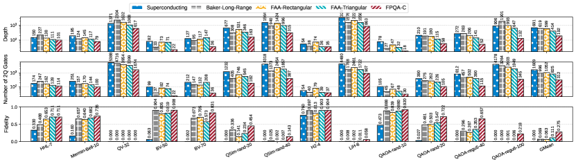
Comparison of FPQA with Other Quantum Architectures. Fig. 14 shows FPQA-C outperforming four alternative architectures in fidelity, 2Q gate count, and depth (number of parallel 2Q layers), exceeding the strongest baseline, FAA-Triangular, by factors of 2.5, 2.6, and 2.2, respectively. Large and complicated circuits like QSim-rand benefit the most due higher connectivity and lower SWAP overhead. In simpler circuits like H2 simulations, different architectures perform comparably.
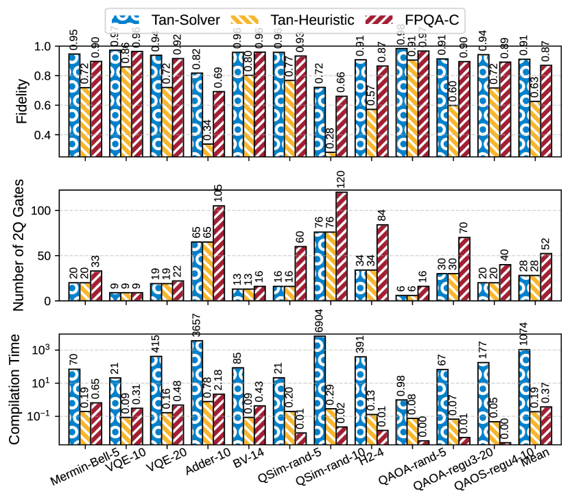
Comparison of FPQA-C with Other Compilers on FPQA. As indicated in the last column of Table II, Tan-Solver [80] is infeasible for circuits with more than 20 qubits within a 24-hour limit. Consequently, smaller circuits are used for comparisons in Fig. 15. For a fair comparison, FPQA-C employs a single AOD, as two baselines lack multi-AOD support. Tan-Heuristic [80] exhibits the fastest compilation time but suffers from low fidelity due to excessive atom transfers, making it unsuitable for large circuits. In contrast, FPQA-C maintains an average fidelity of 87%, comparable to solver-based compilers, while being approximately 3,000 times faster for small-scale problems. This speed advantage is exacerbated for larger problems as the solver-based compiler times out due to exponential time and memory requirements.
Comparison of FPQA-C with Geyser. Geyser [70] suggests using multi-qubit gates to synthesize quantum circuit targets by minimizing the pulses used to perform multi-qubit gates. Tab. III shows the number of pulses used for multi-qubit gates for our compiler and Geyser. We restrict the max function call in the dual-annealing operation to for fair comparisons. The table shows that our compiler outperforms Geyser significantly, reducing at most 5.8 pulses.
VI-C Analysis
What Kind of Circuits are More Suitable for FPQA?
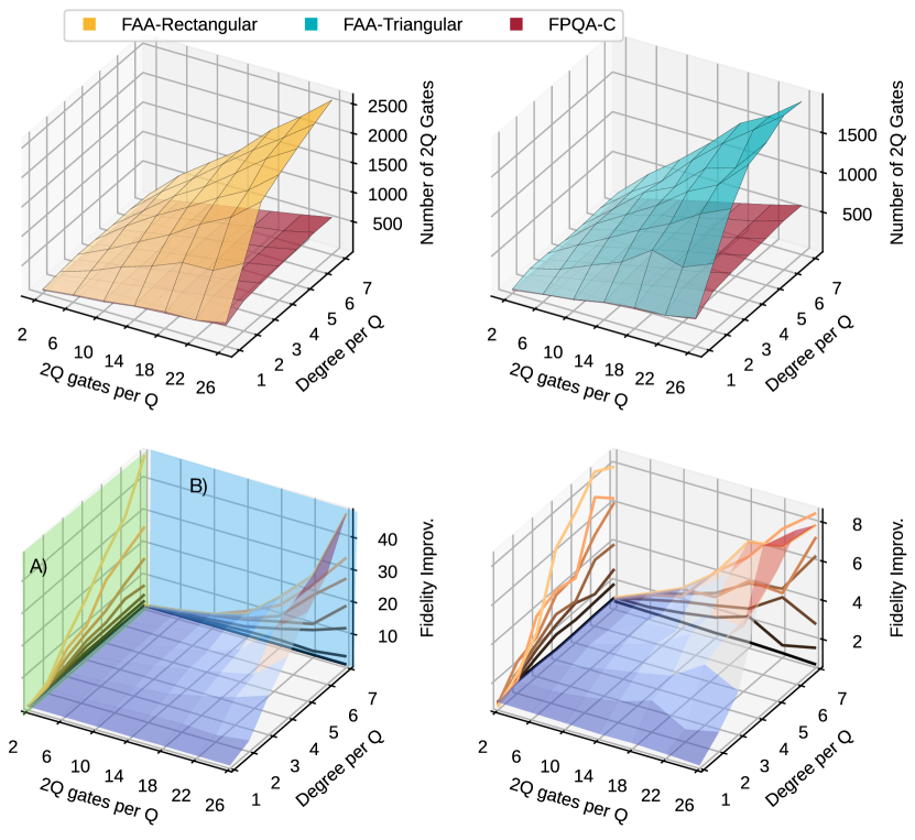
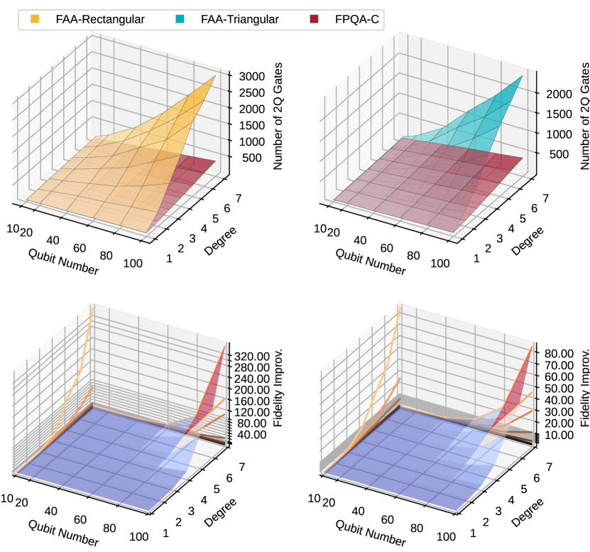
(a) Generic (Arbitrary) Circuits. We analyze the efficacy of FPQA on generic circuits in Fig. 16. Here, we generate random circuits with 40 qubits and varying average 2Q gates per qubit and qubit degrees. 2Q gate per qubit indicates how many gates involve a certain qubit. The degree is the number of unique qubits a given qubit interacts with. The 2Q gate count informs circuit depth, whereas the degree indicates gate locality. In the figure, each surface’s X and Y axis represents the 2Q gate per qubit and qubit degree, respectively. The Z axis is the number of 2Q gates and relative fidelity improvement for the first and second rows. In the second row, we also project the surface into plane A (the Y-Z plane colored by green) and plane B (the X-Z plane colored by blue). Each line in plane A represents the fidelity improvement under a fixed 2Q gate per qubit and varying degree. In contrast, each line in plane B represents the fidelity improvement under a fixed degree and varying 2Q gate per qubit. This setting is similar in Fig. 17 and Fig. 18. The results show the following insights clearly: (1) FPQA-C excels in high-degree circuits. In low-degree, well-localized circuits, FPQA-C’s performance marginally falls behind FAA due to higher decoherence incurred by movement. (2) Deeper circuits benefit more from FPQA-C, evidenced by widening fidelity gaps as 2Q gate count per qubit increases.
| Benchmark | HHL-7 | Mermin-Bell-10 | QV-32 | BV-50 | BV-70 |
|---|---|---|---|---|---|
| Geyser [70] | 384 | 432 | 10,197 | 222 | 624 |
| FPQA-C | 342 | 300 | 5,022 | 66 | 108 |
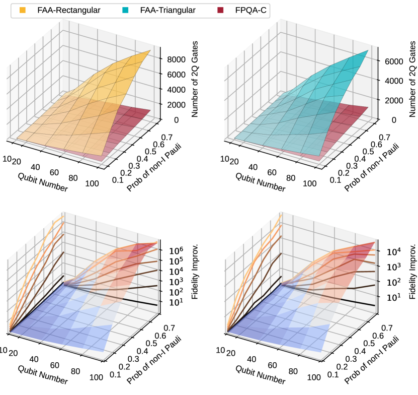
(b) QAOA and Quantum Simulation Circuits. In Fig. 17 and 18, we present results for QAOA and QSim circuits with varying properties. For QAOA, we generate regular graphs with different degrees. For QSim, we change the probability for each Hamiltonian term being a non- operator. The graph degree in QAOA and probability of non-I terms resemble the qubit degree discussed in the previous paragraph, as they all indicate the locality of the problem. The previous insights still hold here. The more non-local the program is, the higher the advantage FPQA-C is. Besides, FPQA-C is better for circuits with more qubits and depth.
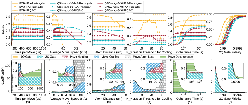
Sensitivity Analysis on Hardware Parameters. In Fig. 19, we conduct a sensitivity analysis on six key hardware parameters. The top row displays the circuit fidelities for three benchmarks—BV-70, QSim-rand-20, and QAOA-regu5-40 under different parameter settings. Comparative data for FPQA-C, FAA-Rectangular, and FAA-Triangular are also provided. The second row elucidates the error breakdown for BV-70 by calculating . Various error sources are color-coded, including 1Q gate error, 2Q gate error, movement heating error, cooling overhead error, atom loss during movement, and movement decoherence error. Insets with a truncated y-axis range are included for detail. A fixed parameter setting corresponds to a vertical line in the figure, and the impact of each error source can be seen from the interaction between the colored area and the vertical line. The longer the intersection, the higher the impact of the error source.
(a) Time per Move. We vary the time per movement from 100 to 1000s. According to Eq.2, shorter times increase the vibrational quantum number (), causing significant atom loss. In the extreme case, where T_per_move smaller than 150, the heating of one single step can exceed , making the cooling procedure no use. When T_per_move is smaller than 200, the cooling can help reduce movement heating error but inevitably incurs large cooling overhead. As T_per_move increases, the decoherence error dominates. The optimal setting is around 300s, where the decoherence and heating are comparable, which is within the 200 to 400s realistic range [11]. For all three benchmarks, FPQA-C outperforms baselines when T_per_move exceeds 200s and slightly decreases when T_per_move further increases.
(b) Average Move Speed. We also present the previous results in a different way by showing the atom movement speed, which is inversely related to T_per_move. Faster speeds induce atom loss, while slower speeds elevate decoherence error. QAOA and QSim benchmarks exhibit faster optimal speeds than arbitrary circuits, attributable to their smaller size.
(c) Atom Distance. We vary the SLM atom separation from 1m to 60m. Larger distances proportionally elevate with rate, increasing heating error. Cooling operations stabilize this error but introduce overhead, dominating at 60m. FPQA-C outperforms baselines for distances under 40m. In experiments, we adopt the 15m setting from [11], where the heating error is minimal.
(d) for Cooling. We employ cooling to mitigate the heating and atom loss caused by excessive . Frequent cooling introduces 2Q gate errors. Using a 60s atom distance to examine trade-offs, we find a low threshold causes significant cooling errors, while a high threshold results in severe atom loss. An optimal threshold range of 12 to 25 minimizes overall impact; we use a threshold of 15 in our experiments.
(e) Coherence Time. Coherence time impacts more on FPQA than to FAA since FPQA execution time is much longer due to movements. With movement time (300s) significantly exceeding 1Q and 2Q gate times (625ns, 380ns), FPQA benefits more from extended coherence time. Comparative analysis shows FPQA outperforms when coherence time exceeds 1s, a threshold generally met in practice as per [11] and [61].
(f) 2Q Gate Fidelity. For fidelities below 0.9999, 2Q gate errors dominate, as indicated in (f). Remarkably, FAA and Geyser outperform FPQA when 2Q fidelity exceeds 0.9999, owing to minimal SWAP overheads. Nonetheless, under current achievable 2Q fidelity and coherence time [11, 25] FPQA-C remains more reliable.
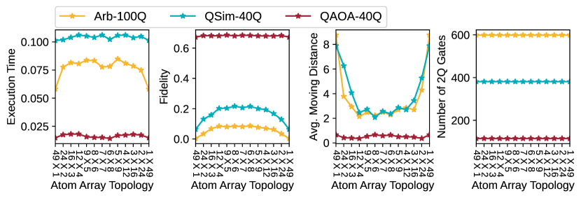
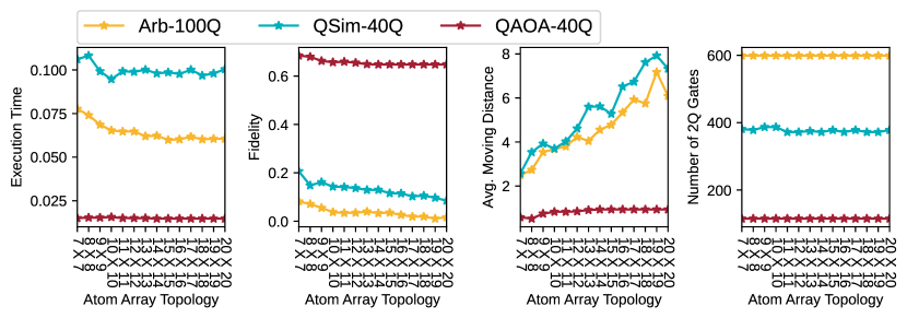
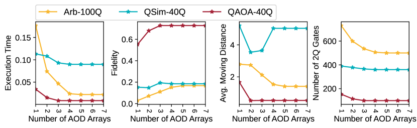
Impact of the Array Topology. We also examine the execution time, fidelity, average moving distance (mm), and 2Q gate count under different array configurations. Benchmarks are 100Q arbitrary circuit with ten gates per qubit; 40Q simulation with probability being non- and ten strings; 40Q QAOA with 5-regular graph.
(a) Different Row-Col Ratio under Same Qubit Number Fig. 20(a) examines the impact of array shape while maintaining the same overall atom count. For all three tasks, square arrays maximize fidelity due to shorter movement distances, as the distance plot shows. However, the execution time increases slightly for square-like topology because they impose stronger constraints for the movement and reduce the parallelism.
(b) Different Qubit Number, Row=Col. Fig. 20(b) analyzes the effects of varying array sizes from to . The optimal fidelity is achieved for all three tasks with a array. As the array size expands, FPQA-C preferentially maps qubits to diagonal atoms, increasing parallelism and reducing execution time. However, this diagonal mapping lengthens moving distances without significantly altering the 2Q gate count, leading to decreased fidelity due to movement heating.
(c) Different Number of AOD Arrays. Fig. 20(c) examines the impact of the number of AODs, ranging from 1 to 7. Additional AODs enhance the coupling map, and the relaxation of order-preserving constraints allows for more efficient movements—these two reasons combined reduce the 2Q gate count and execution time, and increase the fidelity.
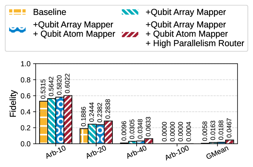
Breakdown of Technique-Induced Improvements. Fig. 21 delineates the contributions of individual techniques to overall performance. We evaluated random circuits with 26 gates per qubit. For the baseline, we adopt the qiskit’s dense mapping instead of the greedy mapping that maximizes the inter-array cut; we also use a random qubit-atom mapper rather than the load balance mapper; finally, we use a serial router that performs one gate at a time instead of parallelizing the gate. For the other experiments, we add these techniques cumulatively. On average, our qubit-array mapper gives rise to 2.81 better fidelity than the dense mapper and subsequent diagonal-first qubit-atom mapper gives rise to 1.15 higher fidelity. Finally, the high parallelism router brings 2.48 fidelity improvement. Combining all three methods, we have 8.05 higher fidelity.
VI-D Evaluation of Surface Code Error Correction
Setup of Quantum Error Correction. We explore two models for mid-circuit measurements in quantum error correction: data qubit shelving [31] and isolating AOD-syndrome qubits for measurement—shelving transfers data qubits to a protected state with the same fidelity as a 2Q gate. Moving AOD qubits incurs a modeled heating error. We employ PyMatching [34] for logical error simulations under varying code distances and error models and use Microsoft’s resource estimator [8] for resource evaluation. The rotated-z surface code [12] serves as our error correction code.
Logical Error Rate and Error Correction Threshold.
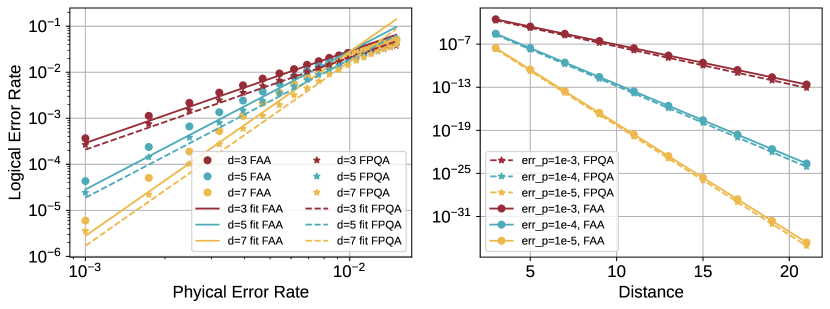
We assess the correlation between logical and physical error rates in surface codes with distance , executing error correction cycles to mitigate measurement errors [20]. The logical error rate can be modeled as [8], where is the error threshold, is the physical error rate, is the code distance, and is a constant. Our fitting yields for FPQA and for FAA, which employs qubit shelving. Compared to FPQA, the shelving method exhibits a higher error pre-factor and a lower error threshold, signifying inferior performance. This is attributed to the localized interactions among syndrome qubits in surface codes, which minimize movement distance and enable heating error reset post-measurement. Fig. 22 right depicts the exponential decay of with respect to .
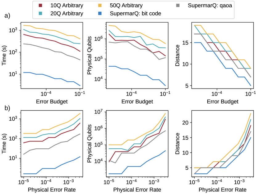
Resource Estimation about Error Budget and Physical Error rate. Even with error correction, a residual failure probability exists, termed the error budget. A lower error budget necessitates higher resources, including code distance, physical qubits, and execution time, as delineated in Fig. 23 left. Conversely, a reduced physical error rate leads to lower resource requirements, as depicted in Fig. 23 right.
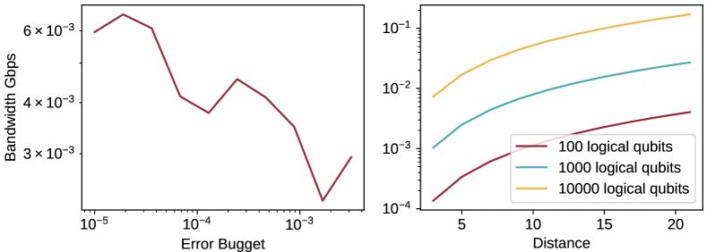
Classical Bandwidth Requirement. The bandwidth requirement for classical control in error correction is negatively related to the error budget, as shown in Fig. 24 left. Reduced code distance and measurement count contribute to this trend. However, some exceptions exist where bandwidth requirements rise with increasing error budget, attributable to reduced execution time. As code distance increases, the bandwidth requirement of the FPQA QEC experiences a slight uptick, as depicted in Fig. 24 right.
VII Related Works
Compilers for Emerging Quantum Architectures Besides widely used superconducting quantum computers, researchers recently have increasing interest on new quantum computing hardware such as neutral atom machines and trapped ion machines. In this work, we have discussed the compiler design from previous neutral atom works [6, 70, 80]. In addition, a number of compilers designed for trapped ion systems have been proposed in recent years, including TILT [98] for a linear chain of trapped ions, Ref. [67] for Quantum Charge Coupled Device-based trapped ion architectures, and Ref. [43] for shuttling based trapped ion architectures. Many compilation techniques for various settings have also been proposed [73, 83, 19, 71, 66, 84, 48, 64, 59, 102, 63, 60, 14, 100, 32, 87, 10, 56, 18, 88, 101, 69, 98, 86, 33, 21, 51, 44, 15]. In this work, we are targeting an emerging FPQA device implemented with dynamically reconfigurable atom arrays. Since the coupling map is dynamic, previous compiler techniques cannot be directly inherited. Therefore, we design a flying ancilla-based compilation framework which delivers low depth compiled circuits with high scalability.
Qubit Mapping and Instruction Scheduling Since noise forms the bottleneck of NISQ machines, many noise-adaptive quantum compilation techniques have been proposed [73, 83, 19, 71, 89, 90, 91, 92, 95, 94, 93, 105]. Examples include various gate errors which can be suppressed by qubit mapping [66, 84, 48, 64, 59, 102], composite pulses [63, 60, 14, 100], dynamical decoupling [32, 87, 10, 56, 18], randomized compiling [88], hidden inverses [101], instruction scheduling [69, 98, 104], frequency tuning [86, 33, 21], parallel execution on multiple machines [79], algorithm-aware compilation [51, 44, 15], qubit specific basis gate [57, 50] and various pulse level optimizations [55, 52, 53, 54]. Qubit mapping and routing, also named quantum layout synthesis or qubit allocation/placement, has been a popular research topic in the QC community [47, 97, 68, 103, 82, 81, 62, 76, 107, 106, 65, 27]. Instruction scheduling has also been widely explored [69, 98, 77, 79, 57, 50]. The most relevant previous work is Brandhofer et al. [13] which considers a hypothetical atom array architecture with ‘1D displacement’ reconfigurability, a much more restrictive architecture than FPQA. They construct a potential coupling graph of all potential connections and leverage an exact router to insert SWAPs, which limits the scalability.
VIII Conclusion and Outlook
We architect the emerging field programmable quantum array (FPQA) with runtime-movable atoms. On this highly flexible FPQA, we propose a qubit mapper and a router to reduce the SWAP overhead and keep high parallelism of 2Q gate executions. Compared to other architectures or compilers, our FPQA-C significantly reduces circuit depth and 2Q gate count. We hope this work can open up the avenue for future research on FPQA.
References
- [1] M. Alam, A. Ash-Saki, and S. Ghosh, “Circuit compilation methodologies for quantum approximate optimization algorithm,” in 53rd Annual IEEE/ACM International Symposium on Microarchitecture, MICRO 2020, Athens, Greece, October 17-21, 2020. IEEE, 2020, pp. 215–228. [Online]. Available: https://doi.org/10.1109/MICRO50266.2020.00029
- [2] M. Alam, A. Ash-Saki, and S. Ghosh, “Circuit compilation methodologies for quantum approximate optimization algorithm,” in 2020 53rd Annual IEEE/ACM International Symposium on Microarchitecture (MICRO). IEEE, 2020, pp. 215–228.
- [3] ——, “An efficient circuit compilation flow for quantum approximate optimization algorithm,” in 2020 57th ACM/IEEE Design Automation Conference (DAC). IEEE, 2020, pp. 1–6.
- [4] M. Alam, A. Ash-Saki, J. Li, A. Chattopadhyay, and S. Ghosh, “Noise resilient compilation policies for quantum approximate optimization algorithm,” in Proceedings of the 39th International Conference on Computer-Aided Design, 2020, pp. 1–7.
- [5] F. Arute, K. Arya, R. Babbush, D. Bacon, J. C. Bardin, R. Barends, R. Biswas, S. Boixo, F. G. Brandao, D. A. Buell et al., “Quantum supremacy using a programmable superconducting processor,” Nature, vol. 574, no. 7779, pp. 505–510, 2019.
- [6] J. M. Baker, A. Litteken, C. Duckering, H. Hoffmann, H. Bernien, and F. T. Chong, “Exploiting long-distance interactions and tolerating atom loss in neutral atom quantum architectures,” in 2021 ACM/IEEE 48th Annual International Symposium on Computer Architecture (ISCA). IEEE, 2021, pp. 818–831.
- [7] J. Beugnon, C. Tuchendler, H. Marion, A. Gaëtan, Y. Miroshnychenko, Y. R. Sortais, A. M. Lance, M. P. Jones, G. Messin, A. Browaeys et al., “Two-dimensional transport and transfer of a single atomic qubit in optical tweezers,” Nature Physics, vol. 3, no. 10, pp. 696–699, 2007.
- [8] M. E. Beverland, P. Murali, M. Troyer, K. M. Svore, T. Hoeffler, V. Kliuchnikov, G. H. Low, M. Soeken, A. Sundaram, and A. Vaschillo, “Assessing requirements to scale to practical quantum advantage,” arXiv preprint arXiv:2211.07629, 2022.
- [9] M. E. Beverland, P. Murali, M. Troyer, K. M. Svore, T. Hoefler, V. Kliuchnikov, G. H. Low, M. Soeken, A. Sundaram, and A. Vaschillo, “Assessing requirements to scale to practical quantum advantage,” Nov. 2022, arXiv:2211.07629 [quant-ph]. [Online]. Available: http://arxiv.org/abs/2211.07629
- [10] M. J. Biercuk, H. Uys, A. P. VanDevender, N. Shiga, W. M. Itano, and J. J. Bollinger, “Optimized dynamical decoupling in a model quantum memory,” Nature, vol. 458, no. 7241, pp. 996–1000, 2009.
- [11] D. Bluvstein, H. Levine, G. Semeghini, T. T. Wang, S. Ebadi, M. Kalinowski, A. Keesling, N. Maskara, H. Pichler, M. Greiner et al., “A quantum processor based on coherent transport of entangled atom arrays,” Nature, vol. 604, no. 7906, pp. 451–456, 2022.
- [12] H. Bombín and M. A. Martin-Delgado, “Optimal resources for topological two-dimensional stabilizer codes: Comparative study,” Physical Review A, vol. 76, no. 1, p. 012305, 2007.
- [13] S. Brandhofer, H. P. Büchler, and I. Polian, “Optimal mapping for near-term quantum architectures based on Rydberg atoms,” in Proceedings of the 40th IEEE/ACM International Conference on Computer-Aided Design, ser. ICCAD ’21. Munich, Germany: Association for Computing Machinery, Nov. 2021.
- [14] K. R. Brown, A. W. Harrow, and I. L. Chuang, “Arbitrarily accurate composite pulse sequences,” Physical Review A, vol. 70, no. 5, p. 052318, 2004.
- [15] J. Cheng, H. Wang, Z. Liang, Y. Shi, S. Han, and X. Qian, “Topgen: Topology-aware bottom-up generator for variational quantum circuits,” arXiv preprint arXiv:2210.08190, 2022.
- [16] A. Coja-Oghlan, C. Moore, and V. Sanwalani, “Max k-cut and approximating the chromatic number of random graphs,” in International Colloquium on Automata, Languages, and Programming. Springer, 2003, pp. 200–211.
- [17] J. P. Covey, I. S. Madjarov, A. Cooper, and M. Endres, “2000-times repeated imaging of strontium atoms in clock-magic tweezer arrays,” Physical review letters, vol. 122, no. 17, p. 173201, 2019.
- [18] P. Das, S. Tannu, S. Dangwal, and M. Qureshi, “Adapt: Mitigating idling errors in qubits via adaptive dynamical decoupling,” in MICRO-54: 54th Annual IEEE/ACM International Symposium on Microarchitecture, 2021, pp. 950–962.
- [19] P. Das, S. Tannu, and M. Qureshi, “Jigsaw: Boosting fidelity of nisq programs via measurement subsetting,” in MICRO-54: 54th Annual IEEE/ACM International Symposium on Microarchitecture, 2021, pp. 937–949.
- [20] E. Dennis, A. Kitaev, A. Landahl, and J. Preskill, “Topological quantum memory,” Journal of Mathematical Physics, vol. 43, no. 9, pp. 4452–4505, 2002.
- [21] Y. Ding, P. Gokhale, S. F. Lin, R. Rines, T. Propson, and F. T. Chong, “Systematic crosstalk mitigation for superconducting qubits via frequency-aware compilation,” in 2020 53rd Annual IEEE/ACM International Symposium on Microarchitecture (MICRO). IEEE, 2020, pp. 201–214.
- [22] C. Duckering, J. M. Baker, A. Litteken, and F. T. Chong, “Orchestrated trios: compiling for efficient communication in quantum programs with 3-qubit gates,” in ASPLOS ’21: 26th ACM International Conference on Architectural Support for Programming Languages and Operating Systems, Virtual Event, USA, April 19-23, 2021, T. Sherwood, E. D. Berger, and C. Kozyrakis, Eds. ACM, 2021, pp. 375–385. [Online]. Available: https://doi.org/10.1145/3445814.3446718
- [23] S. Ebadi, A. Keesling, M. Cain, T. T. Wang, H. Levine, D. Bluvstein, G. Semeghini, A. Omran, J.-G. Liu, R. Samajdar, X.-Z. Luo, B. Nash, X. Gao, B. Barak, E. Farhi, S. Sachdev, N. Gemelke, L. Zhou, S. Choi, H. Pichler, S.-T. Wang, M. Greiner, V. Vuletić, and M. D. Lukin, “Quantum optimization of maximum independent set using rydberg atom arrays,” Science, vol. 376, no. 6598, pp. 1209–1215, 2022. [Online]. Available: https://www.science.org/doi/abs/10.1126/science.abo6587
- [24] S. Ebadi, T. T. Wang, H. Levine, A. Keesling, G. Semeghini, A. Omran, D. Bluvstein, R. Samajdar, H. Pichler, W. W. Ho et al., “Quantum phases of matter on a 256-atom programmable quantum simulator,” Nature, vol. 595, no. 7866, pp. 227–232, 2021.
- [25] S. J. Evered, D. Bluvstein, M. Kalinowski, S. Ebadi, T. Manovitz, H. Zhou, S. H. Li, A. A. Geim, T. T. Wang, N. Maskara et al., “High-fidelity parallel entangling gates on a neutral atom quantum computer,” arXiv preprint arXiv:2304.05420, 2023.
- [26] S. J. Evered, D. Bluvstein, M. Kalinowski, S. Ebadi, T. Manovitz, H. Zhou, S. H. Li, A. A. Geim, T. T. Wang, N. Maskara, H. Levine, G. Semeghini, M. Greiner, V. Vuletic, and M. D. Lukin, “High-fidelity parallel entangling gates on a neutral atom quantum computer,” 2023.
- [27] H. Fan, C. Guo, and W. Luk, “Optimizing quantum circuit placement via machine learning,” in Proceedings of the 59th ACM/IEEE Design Automation Conference, ser. DAC ’22. New York, NY, USA: Association for Computing Machinery, 2022, p. 19–24. [Online]. Available: https://doi.org/10.1145/3489517.3530403
- [28] A. G. Fowler, M. Mariantoni, J. M. Martinis, and A. N. Cleland, “Surface codes: Towards practical large-scale quantum computation,” Physical Review A, vol. 86, no. 3, p. 032324, 2012.
- [29] P. Gokhale, A. Javadi-Abhari, N. Earnest, Y. Shi, and F. T. Chong, “Optimized quantum compilation for near-term algorithms with openpulse,” in 2020 53rd Annual IEEE/ACM International Symposium on Microarchitecture (MICRO). IEEE, 2020, pp. 186–200.
- [30] T. M. Graham, Y. Song, J. Scott, C. Poole, L. Phuttitarn, K. Jooya, P. Eichler, X. Jiang, A. Marra, B. Grinkemeyer, M. Kwon, M. Ebert, J. Cherek, M. T. Lichtman, M. Gillette, J. Gilbert, D. Bowman, T. Ballance, C. Campbell, E. D. Dahl, O. Crawford, N. S. Blunt, B. Rogers, T. Noel, and M. Saffman, “Multi-qubit entanglement and algorithms on a neutral-atom quantum computer,” Nature, vol. 604, no. 7906, pp. 457–462, Apr. 2022. [Online]. Available: https://www.nature.com/articles/s41586-022-04603-6
- [31] T. Graham, L. Phuttitarn, R. Chinnarasu, Y. Song, C. Poole, K. Jooya, J. Scott, A. Scott, P. Eichler, and M. Saffman, “Mid-circuit measurements on a neutral atom quantum processor,” arXiv preprint arXiv:2303.10051, 2023.
- [32] E. L. Hahn, “Spin echoes,” Physical review, vol. 80, no. 4, p. 580, 1950.
- [33] F. Helmer, M. Mariantoni, A. G. Fowler, J. von Delft, E. Solano, and F. Marquardt, “Cavity grid for scalable quantum computation with superconducting circuits,” EPL (Europhysics Letters), vol. 85, no. 5, p. 50007, 2009.
- [34] O. Higgott and C. Gidney, “Sparse blossom: correcting a million errors per core second with minimum-weight matching,” arXiv preprint arXiv:2303.15933, 2023.
- [35] J. Hsu, “Ces 2018: Intel’s 49-qubit chip shoots for quantum supremacy,” https://spectrum.ieee.org/tech-talk/computing/hardware/intels-49qubit-chip-aims-for-quantum-supremacy.
- [36] F. Hua, M. Wang, G. Li, B. Peng, C. Liu, M. Zheng, S. A. Stein, Y. Ding, E. Z. Zhang, T. S. Humble, and A. Li, “Qasmtrans: A QASM quantum transpiler framework for NISQ devices,” in Proceedings of the SC ’23 Workshops of The International Conference on High Performance Computing, Network, Storage, and Analysis, SC-W 2023, Denver, CO, USA, November 12-17, 2023. ACM, 2023, pp. 1468–1477. [Online]. Available: https://doi.org/10.1145/3624062.3624222
- [37] IBM, “Ibm quantum,” https://quantum-computing.ibm.com.
- [38] ——, “Ibm unveils 400 qubit-plus quantum processor and next-generation ibm quantum system two,” https://newsroom.ibm.com/2022-11-09-IBM-Unveils-400-Qubit-Plus-Quantum-Processor-and-Next-Generation-IBM-Quantum-System-Two.
- [39] ——, “IBM unveils breakthrough 127-qubit quantum processor,” https://newsroom.ibm.com/2021-11-16-IBM-Unveils-Breakthrough-127-Qubit-Quantum-Processor.
- [40] D. Jaksch, J. I. Cirac, P. Zoller, S. L. Rolston, R. Côté, and M. D. Lukin, “Fast quantum gates for neutral atoms,” Phys. Rev. Lett., vol. 85, pp. 2208–2211, Sep 2000. [Online]. Available: https://link.aps.org/doi/10.1103/PhysRevLett.85.2208
- [41] J. Kelly, “A preview of bristlecone, google’s new quantum processor,” https://ai.googleblog.com/2018/03/a-preview-of-bristlecone-googles-new.html.
- [42] P. Krantz, M. Kjaergaard, F. Yan, T. P. Orlando, S. Gustavsson, and W. D. Oliver, “A quantum engineer’s guide to superconducting qubits,” Applied Physics Reviews, vol. 6, no. 2, p. 021318, 2019.
- [43] F. Kreppel, C. Melzer, J. Wagner, J. Hilder, U. Poschinger, F. Schmidt-Kaler, and A. Brinkmann, “Quantum Circuit Compiler for a Shuttling-Based Trapped-Ion Quantum Computer,” 7 2022.
- [44] L. Lao and D. E. Browne, “2qan: A quantum compiler for 2-local qubit hamiltonian simulation algorithms,” in Proceedings of the 49th Annual International Symposium on Computer Architecture, 2022, pp. 351–365.
- [45] H. Levine, A. Keesling, G. Semeghini, A. Omran, T. T. Wang, S. Ebadi, H. Bernien, M. Greiner, V. Vuletić, H. Pichler, and M. D. Lukin, “Parallel implementation of high-fidelity multiqubit gates with neutral atoms,” Phys. Rev. Lett., vol. 123, p. 170503, Oct 2019. [Online]. Available: https://link.aps.org/doi/10.1103/PhysRevLett.123.170503
- [46] A. Li, S. Stein, S. Krishnamoorthy, and J. Ang, “Qasmbench: A low-level quantum benchmark suite for nisq evaluation and simulation,” ACM Transactions on Quantum Computing, vol. 4, no. 2, feb 2023. [Online]. Available: https://doi.org/10.1145/3550488
- [47] G. Li, Y. Ding, and Y. Xie, “Tackling the qubit mapping problem for NISQ-era quantum devices,” in Proceedings of the Twenty-Fourth International Conference on Architectural Support for Programming Languages and Operating Systems, ser. ASPLOS ’19. Providence, RI, USA: ACM Press, 2019, pp. 1001–1014.
- [48] ——, “Tackling the qubit mapping problem for nisq-era quantum devices,” in Proceedings of the Twenty-Fourth International Conference on Architectural Support for Programming Languages and Operating Systems, 2019, pp. 1001–1014.
- [49] ——, “Towards efficient superconducting quantum processor architecture design,” in Proceedings of the Twenty-Fifth International Conference on Architectural Support for Programming Languages and Operating Systems, 2020, pp. 1031–1045.
- [50] G. Li, Y. Shi, and A. Javadi-Abhari, “Software-hardware co-optimization for computational chemistry on superconducting quantum processors,” in 2021 ACM/IEEE 48th Annual International Symposium on Computer Architecture (ISCA). IEEE, 2021, pp. 832–845.
- [51] G. Li, A. Wu, Y. Shi, A. Javadi-Abhari, Y. Ding, and Y. Xie, “Paulihedral: a generalized block-wise compiler optimization framework for quantum simulation kernels,” in Proceedings of the 27th ACM International Conference on Architectural Support for Programming Languages and Operating Systems, 2022, pp. 554–569.
- [52] Z. Liang, J. Cheng, H. Ren, H. Wang, F. Hua, Z. Song, Y. Ding, F. Chong, S. Han, Y. Shi, and X. Qian, “Napa: Intermediate-level variational native-pulse ansatz for variational quantum algorithms,” 2023.
- [53] Z. Liang, J. Cheng, Z. Song, H. Ren, R. Yang, H. Wang, K. Liu, P. Kogge, T. Li, Y. Ding et al., “Towards advantages of parameterized quantum pulses,” arXiv preprint arXiv:2304.09253, 2023.
- [54] Z. Liang, Z. Song, J. Cheng, Z. He, J. Liu, H. Wang, R. Qin, Y. Wang, S. Han, X. Qian, and Y. Shi, “Hybrid gate-pulse model for variational quantum algorithms,” in 2023 60th ACM/IEEE Design Automation Conference (DAC), 2023, pp. 1–6.
- [55] Z. Liang*, H. Wang*, J. Cheng, Y. Ding, H. Ren, Z. Gao, Z. Hu, D. S. Boning, X. Qian, S. Han et al., “Variational quantum pulse learning,” in 2022 IEEE International Conference on Quantum Computing and Engineering (QCE). IEEE, 2022, pp. 556–565.
- [56] D. A. Lidar, “Review of decoherence free subspaces, noiseless subsystems, and dynamical decoupling,” Adv. Chem. Phys, vol. 154, pp. 295–354, 2014.
- [57] S. F. Lin, S. Sussman, C. Duckering, P. S. Mundada, J. M. Baker, R. S. Kumar, A. A. Houck, and F. T. Chong, “Let each quantum bit choose its basis gates,” arXiv preprint arXiv:2208.13380, 2022.
- [58] D. Litinski, “A Game of Surface Codes: Large-Scale Quantum Computing with Lattice Surgery,” Quantum, vol. 3, p. 128, Mar. 2019, arXiv: 1808.02892. [Online]. Available: http://arxiv.org/abs/1808.02892
- [59] L. Liu and X. Dou, “Qucloud: A new qubit mapping mechanism for multi-programming quantum computing in cloud environment,” in 2021 IEEE International Symposium on High-Performance Computer Architecture (HPCA), 2021, pp. 167–178.
- [60] G. H. Low, T. J. Yoder, and I. L. Chuang, “Optimal arbitrarily accurate composite pulse sequences,” Physical Review A, vol. 89, no. 2, p. 022341, 2014.
- [61] I. S. Madjarov, J. P. Covey, A. L. Shaw, J. Choi, A. Kale, A. Cooper, H. Pichler, V. Schkolnik, J. R. Williams, and M. Endres, “High-fidelity entanglement and detection of alkaline-earth rydberg atoms,” Nature Physics, vol. 16, no. 8, pp. 857–861, 2020.
- [62] D. Maslov, S. M. Falconer, and M. Mosca, “Quantum circuit placement,” IEEE Transactions on Computer-Aided Design of Integrated Circuits and Systems, vol. 27, no. 4, pp. 752–763, Apr. 2008.
- [63] J. T. Merrill and K. R. Brown, “Progress in compensating pulse sequences for quantum computation,” Quantum Information and Computation for Chemistry, pp. 241–294, 2014.
- [64] A. Molavi, A. Xu, M. Diges, L. Pick, S. Tannu, and A. Albarghouthi, “Qubit mapping and routing via maxsat,” arXiv preprint arXiv:2208.13679, 2022.
- [65] ——, “Qubit mapping and routing via maxsat,” in 55th IEEE/ACM International Symposium on Microarchitecture, MICRO 2022, Chicago, IL, USA, October 1-5, 2022. IEEE, 2022, pp. 1078–1091. [Online]. Available: https://doi.org/10.1109/MICRO56248.2022.00077
- [66] P. Murali, J. M. Baker, A. Javadi-Abhari, F. T. Chong, and M. Martonosi, “Noise-adaptive compiler mappings for noisy intermediate-scale quantum computers,” in Proceedings of the Twenty-Fourth International Conference on Architectural Support for Programming Languages and Operating Systems, 2019, pp. 1015–1029.
- [67] P. Murali, D. M. Debroy, K. R. Brown, and M. Martonosi, “Architecting noisy intermediate-scale trapped ion quantum computers,” in Proceedings of the ACM/IEEE 47th Annual International Symposium on Computer Architecture, ser. ISCA ’20. IEEE Press, 2020, p. 529–542. [Online]. Available: https://doi.org/10.1109/ISCA45697.2020.00051
- [68] P. Murali, N. M. Linke, M. Martonosi, A. J. Abhari, N. H. Nguyen, and C. H. Alderete, “Full-stack, real-system quantum computer studies: Architectural comparisons and design insights,” in Proceedings of the 46th International Symposium on Computer Architecture, ser. ISCA ’19. Phoenix, Arizona: ACM Press, 2019, pp. 527–540.
- [69] P. Murali, D. C. McKay, M. Martonosi, and A. Javadi-Abhari, “Software mitigation of crosstalk on noisy intermediate-scale quantum computers,” in Proceedings of the Twenty-Fifth International Conference on Architectural Support for Programming Languages and Operating Systems, 2020, pp. 1001–1016.
- [70] T. Patel, D. Silver, and D. Tiwari, “Geyser: A compilation framework for quantum computing with neutral atoms,” in Proceedings of the 49th Annual International Symposium on Computer Architecture, ser. ISCA ’22. New York, NY, USA: Association for Computing Machinery, 2022, p. 383–395. [Online]. Available: https://doi.org/10.1145/3470496.3527428
- [71] T. Patel and D. Tiwari, “Qraft: Reverse your quantum circuit and know the correct program output,” in Proceedings of the 26th ACM International Conference on Architectural Support for Programming Languages and Operating Systems, ser. ASPLOS ’21. New York, NY, USA: Association for Computing Machinery, 2021, p. 443–455. [Online]. Available: https://doi.org/10.1145/3445814.3446743
- [72] QuEra, “Quera launches their 256 qubit analog quantum processor on aws,” https://quantumcomputingreport.com/quera-launches-their-256-qubit-analog-quantum-processor-on-aws/.
- [73] G. S. Ravi, K. N. Smith, P. Gokhale, A. Mari, N. Earnest, A. Javadi-Abhari, and F. T. Chong, “Vaqem: A variational approach to quantum error mitigation,” in 2022 IEEE International Symposium on High-Performance Computer Architecture (HPCA). IEEE, 2022, pp. 288–303.
- [74] Rigetti, “Rigetti quantum,” https://www.rigetti.com/.
- [75] M. Saffman, “Quantum computing with atomic qubits and rydberg interactions: progress and challenges,” Journal of Physics B: Atomic, Molecular and Optical Physics, vol. 49, no. 20, p. 202001, oct 2016. [Online]. Available: https://dx.doi.org/10.1088/0953-4075/49/20/202001
- [76] M. Y. Siraichi, V. F. dos Santos, S. Collange, and F. M. Q. Pereira, “Qubit allocation,” in Proceedings of the 2018 International Symposium on Code Generation and Optimization, ser. CGO ’18. Vienna, Austria: ACM Press, 2018, pp. 113–125.
- [77] K. N. Smith, G. S. Ravi, P. Murali, J. M. Baker, N. Earnest, A. Javadi-Abhari, and F. T. Chong, “Error mitigation in quantum computers through instruction scheduling,” 2021. [Online]. Available: https://arxiv.org/abs/2105.01760
- [78] K. N. Smith and M. A. Thornton, “A quantum computational compiler and design tool for technology-specific targets,” in Proceedings of the 46th International Symposium on Computer Architecture, ISCA 2019, Phoenix, AZ, USA, June 22-26, 2019, S. B. Manne, H. C. Hunter, and E. R. Altman, Eds. ACM, 2019, pp. 579–588. [Online]. Available: https://doi.org/10.1145/3307650.3322262
- [79] S. Stein, N. Wiebe, Y. Ding, P. Bo, K. Kowalski, N. Baker, J. Ang, and A. Li, “Eqc: ensembled quantum computing for variational quantum algorithms,” in Proceedings of the 49th Annual International Symposium on Computer Architecture, 2022, pp. 59–71.
- [80] B. Tan, D. Bluvstein, D. M. Lukin, and J. Cong, “Qubit mapping for reconfigurable atom arrays,” ICCAD, 2022.
- [81] B. Tan and J. Cong, “Optimal layout synthesis for quantum computing,” in Proceedings of the 39th IEEE/ACM International Conference on Computer-Aided Design, ser. ICCAD ’20. Virtual Event, USA: Association for Computing Machinery, Jul. 2020.
- [82] ——, “Optimal qubit mapping with simultaneous gate absorption,” in Proceedings of the 40th IEEE/ACM International Conference on Computer-Aided Design, ser. ICCAD ’21. Munich, Germany: Association for Computing Machinery, Nov. 2021.
- [83] S. Tannu, P. Das, R. Ayanzadeh, and M. Qureshi, “Hammer: Boosting fidelity of noisy quantum circuits by exploiting hamming behavior of erroneous outcomes,” in Proceedings of the 27th ACM International Conference on Architectural Support for Programming Languages and Operating Systems, ser. ASPLOS ’22. New York, NY, USA: Association for Computing Machinery, 2022, p. 529–540. [Online]. Available: https://doi.org/10.1145/3503222.3507703
- [84] S. S. Tannu and M. K. Qureshi, “Not all qubits are created equal: a case for variability-aware policies for nisq-era quantum computers,” in Proceedings of the Twenty-Fourth International Conference on Architectural Support for Programming Languages and Operating Systems, 2019, pp. 987–999.
- [85] T. Tomesh, P. Gokhale, V. Omole, G. S. Ravi, K. N. Smith, J. Viszlai, X.-C. Wu, N. Hardavellas, M. R. Martonosi, and F. T. Chong, “Supermarq: A scalable quantum benchmark suite,” in 2022 IEEE International Symposium on High-Performance Computer Architecture (HPCA). IEEE, 2022, pp. 587–603.
- [86] R. Versluis, S. Poletto, N. Khammassi, B. Tarasinski, N. Haider, D. J. Michalak, A. Bruno, K. Bertels, and L. DiCarlo, “Scalable quantum circuit and control for a superconducting surface code,” Physical Review Applied, vol. 8, no. 3, p. 034021, 2017.
- [87] L. Viola, E. Knill, and S. Lloyd, “Dynamical decoupling of open quantum systems,” Physical Review Letters, vol. 82, no. 12, p. 2417, 1999.
- [88] J. J. Wallman and J. Emerson, “Noise tailoring for scalable quantum computation via randomized compiling,” Physical Review A, vol. 94, no. 5, p. 052325, 2016.
- [89] H. Wang, Y. Ding, J. Gu, Y. Lin, D. Z. Pan, F. T. Chong, and S. Han, “Quantumnas: Noise-adaptive search for robust quantum circuits,” in 2022 IEEE International Symposium on High-Performance Computer Architecture (HPCA). IEEE, 2022, pp. 692–708.
- [90] H. Wang, J. Gu, Y. Ding, Z. Li, F. T. Chong, D. Z. Pan, and S. Han, “Quantumnat: quantum noise-aware training with noise injection, quantization and normalization,” in Proceedings of the 59th ACM/IEEE Design Automation Conference, 2022, pp. 1–6.
- [91] H. Wang, Z. Li, J. Gu, Y. Ding, D. Z. Pan, and S. Han, “Qoc: quantum on-chip training with parameter shift and gradient pruning,” in Proceedings of the 59th ACM/IEEE Design Automation Conference, 2022, pp. 655–660.
- [92] H. Wang, P. Liu, J. Cheng, Z. Liang, J. Gu, Z. Li, Y. Ding, W. Jiang, Y. Shi, X. Qian et al., “Quest: Graph transformer for quantum circuit reliability estimation,” in IEEE/ACM International Conference on Computer-Aided Design (ICCAD), 2022.
- [93] H. Wang, P. Liu, Y. Liu, J. Gu, J. Baker, F. T. Chong, and S. Han, “DGR: Tackling Drifted and Correlated Noise in Quantum Error Correction via Decoding Graph Re-weighting,” in arXiv preprint, 2023.
- [94] H. Wang, P. Liu, K. Shao, D. Li, J. Gu, D. Z. Pan, Y. Ding, and S. Han, “Transformerqec: Transferable transformer for quantum error correction code decoding,” in IEEE/ACM International Conference on Computer-Aided Design (ICCAD), FastML for Science Workshop, 2023.
- [95] H. Wang, Y. Liu, P. Liu, J. Gu, Z. Li, Z. Liang, J. Cheng, Y. Ding, X. Qian, Y. Shi, D. Z. Pan, F. T. Chong, and S. Han, “Robuststate: Boosting fidelity of quantum state preparation via noise-aware variational training,” arXiv preprint, 2023.
- [96] H. Wang, B. Tan, P. Liu, Y. Liu, J. Gu, D. Z. Pan, J. Cong, and S. Han, “Q-Pilot: Field Programmable Quantum Array Compilation with Flying Ancillas,” in arXiv preprint, 2023.
- [97] R. Wille, L. Burgholzer, and A. Zulehner, “Mapping quantum circuits to IBM QX architectures using the minimal number of SWAP and H operations,” in Proceedings of the 56th Annual Design Automation Conference 2019, ser. DAC ’19. Las Vegas, NV, USA: ACM Press, 2019.
- [98] X.-C. Wu, D. M. Debroy, Y. Ding, J. M. Baker, Y. Alexeev, K. R. Brown, and F. T. Chong, “Tilt: Achieving higher fidelity on a trapped-ion linear-tape quantum computing architecture,” arXiv preprint arXiv:2010.15876, 2020.
- [99] J. Wurtz, A. Bylinskii, B. Braverman, J. Amato-Grill, S. H. Cantu, F. Huber, A. Lukin, F. Liu, P. Weinberg, J. Long et al., “Aquila: Quera’s 256-qubit neutral-atom quantum computer,” arXiv preprint arXiv:2306.11727, 2023.
- [100] L. Xie, J. Zhai, Z. Zhang, J. Allcock, S. Zhang, and Y.-C. Zheng, “Suppressing zz crosstalk of quantum computers through pulse and scheduling co-optimization,” in Proceedings of the 27th ACM International Conference on Architectural Support for Programming Languages and Operating Systems, 2022, pp. 499–513.
- [101] B. Zhang, S. Majumder, P. H. Leung, S. Crain, Y. Wang, C. Fang, D. M. Debroy, J. Kim, and K. R. Brown, “Hidden inverses: Coherent error cancellation at the circuit level,” arXiv preprint arXiv:2104.01119, 2021.
- [102] C. Zhang, A. B. Hayes, L. Qiu, Y. Jin, Y. Chen, and E. Z. Zhang, “Time-optimal qubit mapping,” in Proceedings of the 26th ACM International Conference on Architectural Support for Programming Languages and Operating Systems, 2021, pp. 360–374.
- [103] ——, “Time-optimal qubit mapping,” in Proceedings of the 26th ACM International Conference on Architectural Support for Programming Languages and Operating Systems, ser. ASPLOS ’21. Virtual USA: ACM, Apr. 2021, pp. 360–374.
- [104] J. Zhang, H. Wang, G. S. Ravi, F. T. Chong, S. Han, F. Mueller, and Y. Chen, “Disq: Dynamic iteration skipping for variational quantum algorithms,” in 2023 IEEE International Conference on Quantum Computing and Engineering (QCE), 2023.
- [105] H. Zheng, G. S. Ravi, H. Wang, K. Setia, F. T. Chong, and J. Liu, “Sncqa: A hardware-efficient equivariant quantum convolutional circuit architecture,” in 2023 IEEE International Conference on Quantum Computing and Engineering (QCE), 2023.
- [106] X. Zhou, Y. Feng, and S. Li, “A Monte Carlo Tree Search Framework for Quantum Circuit Transformation,” arXiv:2008.09331 [quant-ph], Aug. 2020, arXiv: 2008.09331.
- [107] A. Zulehner, A. Paler, and R. Wille, “Efficient mapping of quantum circuits to the IBM QX architectures,” in 2018 Design, Automation Test in Europe Conference Exhibition (DATE). Dresden, Germany: IEEE, Mar. 2018, pp. 1135–1138.