Multiuser Beamforming for Partially-Connected Millimeter Wave Massive MIMO

Chenhao Qi, , Jinlin Hu, Yang Du, Arumugam Nallanathan Copyright (c) 2015 IEEE. Personal use of this material is permitted. However, permission to use this material for any other purposes must be obtained from the IEEE by sending a request to pubs-permissions@ieee.org.This work was supported in part by the National Natural Science Foundation of China under Grants 62071116 and U22B2007. (Corresponding author: Chenhao Qi)Chenhao Qi and Jinlin Hu are with School of Information Science and Engineering, Southeast University, Nanjing 210096, China (Email: {jlhu, qch}@seu.edu.cn).Yang Du is with Huawei Technologies Company Ltd. (Chengdu), Chengdu, China (Email: duyang22@huawei.com).Arumugam Nallanathan is with School of Electronic Engineering and Computer Science, Queen Mary University of London, London, UK (Email: nallanathan@ieee.org).
Abstract

Multiuser beamforming is considered for partially-connected millimeter wave massive MIMO systems. Based on perfect channel state information (CSI), a low-complexity hybrid beamforming scheme that decouples the analog beamformer and the digital beamformer is proposed to maximize the sum-rate. The analog beamformer design is modeled as a phase alignment problem to harvest the array gain. Given the analog beamformer, the digital beamformer is designed by solving a weighted minimum mean squared error problem. Then based on imperfect CSI, an analog-only beamformer design scheme is proposed, where the design problem aims at maximizing the desired signal power on the current user and minimizing the power on the other users to mitigate the multiuser interference. The original problem is then transformed into a series of independent beam nulling subproblems, where an efficient iterative algorithm using the majorization–minimization framework is proposed to solve the subproblems. Simulation results show that, under perfect CSI, the proposed scheme achieves almost the same sum-rate performance as the existing schemes but with lower computational complexity; and under imperfect CSI, the proposed analog-only beamforming design scheme can effectively mitigate the multiuser interference.

Index Terms:
Analog beamforming, hybrid beamforming, millimeter wave (mmWave) communications, partially-connected structure.

I Introduction

Although millimeter wave (mmWave) communications have been widely recognized as an important candidate for future wireless systems owing to the rich spectral resource in mmWave frequency band, they have not yet been commercially deployed for cellular wireless networks [1]. The barriers include the high cost in hardware and the large energy consumption especially for mobile terminals [2]. Though the fully-connected structure is more intensively studied by the academia and has been shown to achieve better performance than the partially-connected structure, the latter has much lower hardware complexity, e.g., much smaller number of phase shifters, and is more preferable by the industry than the former [3].

For multiuser mmWave massive MIMO, hybrid beamforming is generally adopted, where the analog beamformer implemented by the phase shifters achieves directional signal transmission and the digital beamformer mitigates the interference among different users. In [4], aiming at maximizing the sum-rate, a two-stage limited feedback multiuser hybrid beamforming (TSH) scheme is proposed, where the analog beamformer is first designed by beam sweeping and then the base station (BS) trains the effective channels to perform zero-forcing processing with the designed digital beamformer. To further increase the sum-rate, the analog beamformer is designed by performing singular value decomposition (SVD) of the high-dimensional air-interface channel matrix, while the digital beamformer is designed through block diagonalization [5]. In [6], the analog beamformer is designed the same as [5] while the digital beamformer is designed based on successive optimization; and in particular, the digital beamformer of the current user is required to lie in the null space of the effective channels of the remaining users so that the multiuser interference can be mitigated. Note that both [5] and [6] assume that the ideal channel state information (CSI) is available to the hybrid beamformer design.

In this paper, we consider the multiuser beamforming for partially-connected mmWave massive MIMO based on perfect CSI and imperfect CSI, respectively. Our contributions can be summarized as:

  • Based on perfect CSI, we propose a low-complexity hybrid beamforming scheme that decouples the analog beamformer and the digital beamformer to maximize the sum-rate. The analog beamformer design is modeled as a phase alignment problem to harvest the array gain. Given the analog beamformer, the digital beamformer is designed by solving a weighted minimum mean squared error problem.

  • Since perfect CSI is not available in practice, then based on imperfect CSI, an analog-only beamformer design scheme is proposed, where the design problem aims at maximizing the desired signal power on the current user and minimizing the power on the other users to mitigate the multiuser interference. The original problem is then transformed into a series of independent beam nulling subproblems, where an efficient iterative algorithm using the majorization–minimization framework is proposed to solve the subproblems. Different from the existing work, our scheme completely omits the digital beamformer design, so that the pilot overhead in estimating the effective channels can be completely removed.

The rest of the paper is organized as follows. Section II introduces the system model of partially-connected mmWave massive MIMO. In Section III, we investigate the hybrid beamforming based on perfect CSI. Since the perfect CSI is unavailable in practice, we then investigate the analog-only beamforming design based on imperfect CSI in Section IV. The simulation results are presented in Section V, and the paper is concluded in Section VI.

Notations: Symbols for vectors (lower case) and matrices (upper case) are in boldface. For a vector 𝒂𝒂\bm{a}, [𝒂]msubscriptdelimited-[]𝒂𝑚\left[\bm{a}\right]_{m}denotes its m𝑚mth entry. For a matrix 𝑨𝑨\bm{A}, [𝑨]m,:subscriptdelimited-[]𝑨𝑚:\left[\bm{A}\right]_{m,:}, [𝑨]:,nsubscriptdelimited-[]𝑨:𝑛\left[\bm{A}\right]_{:,n}, [𝑨]m,nsubscriptdelimited-[]𝑨𝑚𝑛\left[\bm{A}\right]_{m,n}, 𝑨Tsuperscript𝑨𝑇\bm{A}^{T}, 𝑨1superscript𝑨1\bm{A}^{-1}, 𝑨Hsuperscript𝑨𝐻\bm{A}^{H} and 𝑨Fsubscriptnorm𝑨𝐹\big{\|}\bm{A}\big{\|}_{F} denote the m𝑚mth row, n𝑛nth column, entry on the m𝑚mth row and n𝑛nth column, transpose, inverse, conjugate transpose (Hermitian), and Frobenius norm, respectively. 𝑰Ksubscript𝑰𝐾\bm{I}_{K} and 𝒞𝒩(0,σ2)𝒞𝒩0superscript𝜎2\mathcal{CN}(0,\sigma^{2}) denote an identity matrix of size K𝐾K and the complex Gaussian distribution with zero mean and the variance being σ2superscript𝜎2\sigma^{2}, respectively. The symbols {}\angle\left\{\cdot\right\}, Re{}Re{\rm Re}\left\{\cdot\right\} and |||\cdot| denote the angle, the real part and the absolute value of a complex-valued number, respectively. The symbols \lfloor\cdot\rfloor, blkdiag{}blkdiag{\rm blkdiag}\left\{\cdot\right\}, 𝔼{}𝔼\mathbb{E}\{\cdot\} and \mathbb{C} denote the floor operation, block diagonalization operation, expectation and set of complex-valued numbers, respectively.

II System Model

We consider the downlink transmission of a mmWave massive MIMO, where the BS equipped with NBSsubscript𝑁BSN_{\rm BS} uniform linear array (ULA) antennas and NRFsubscript𝑁RFN_{\rm RF} radio frequency (RF) chains (NBSNRF1much-greater-thansubscript𝑁BSsubscript𝑁RF1N_{\rm BS}\gg N_{\rm RF}\geqslant 1) is assumed to serve K𝐾K single antenna users. The number of users simultaneously served by the BS is constrained by the number of RF chains, i.e., KNRF𝐾subscript𝑁RFK\leqslant N_{\rm RF}. In this paper, we assume K=NRF𝐾subscript𝑁RFK=N_{\rm RF} for simplicity.111In practice, if the number of mobile devices is greater than the number of RF chains, i.e., K>NRF𝐾subscript𝑁RFK>N_{\rm RF}, we can employ some user scheduling algorithms, which select NRFsubscript𝑁RFN_{\rm RF} users from K𝐾K candidate users to serve simultaneously at a time, and select another NRFsubscript𝑁RFN_{\rm RF} users to serve at another time by time-division multiple access (TDMA). The hybrid beamformer at the BS includes a digital beamformer at baseband (BB) and an analog beamformer in the RF domain, denoted as 𝑭BBK×Ksubscript𝑭BBsuperscript𝐾𝐾\bm{F}_{\rm BB}\in\mathbb{C}^{K\times K} and 𝑭RFNBS×Ksubscript𝑭RFsuperscriptsubscript𝑁BS𝐾\bm{F}_{\rm RF}\in\mathbb{C}^{N_{\rm BS}\times K}, respectively. Moreover, we normalize the power gain of the hybrid beamformer by setting 𝑭RF𝑭BBF2=Ksubscriptsuperscriptnormsubscript𝑭RFsubscript𝑭BB2𝐹𝐾\|\bm{F}_{\rm RF}\bm{F}_{\rm BB}\|^{2}_{F}=K to ensure that the hybrid beamformer does not provide any power gain. The received signal by the k𝑘kth user can be expressed as

yk=𝒉kT𝑭RF𝑭BB𝒔+ηk,subscript𝑦𝑘subscriptsuperscript𝒉𝑇𝑘subscript𝑭RFsubscript𝑭BB𝒔subscript𝜂𝑘y_{k}=\bm{h}^{T}_{k}\bm{F}_{\rm RF}\bm{F}_{\rm BB}\bm{s}+\eta_{k}, (1)

where 𝒔[s1,s2,,sK]TK𝒔superscriptsubscript𝑠1subscript𝑠2subscript𝑠𝐾𝑇superscript𝐾\bm{s}\triangleq\left[s_{1},s_{2},\ldots,s_{K}\right]^{T}\in\mathbb{C}^{K} is a data symbol vector subject to the constraint of total transmit power P𝑃P, i.e., 𝔼{𝒔𝒔H}=PK𝑰K𝔼𝒔superscript𝒔𝐻𝑃𝐾subscript𝑰𝐾\mathbb{E}\left\{\bm{s}\bm{s}^{H}\right\}=\frac{P}{K}\bm{I}_{K}, and ηk𝒞𝒩(0,σ2)similar-tosubscript𝜂𝑘𝒞𝒩0superscript𝜎2\eta_{k}\sim\mathcal{CN}\left(0,\sigma^{2}\right) denotes the additive white Gaussian noise. 𝒉kNBSsubscript𝒉𝑘superscriptsubscript𝑁BS\bm{h}_{k}\in\mathbb{C}^{N_{\rm BS}} denotes the channel vector between the BS and the k𝑘kth user.

According to the widely-used Saleh-Valenzuela model [4], which takes into account the limited scattering characteristics in mmWave channels and assumes a geometric channel model with Lksubscript𝐿𝑘L_{k} independent propagation paths, the channel vector 𝒉ksubscript𝒉𝑘\bm{h}_{k} in (1) can be defined as

𝒉k=NBSLkl=1Lkαk,l𝒂(θk,l)subscript𝒉𝑘subscript𝑁BSsubscript𝐿𝑘superscriptsubscript𝑙1subscript𝐿𝑘subscript𝛼𝑘𝑙𝒂subscript𝜃𝑘𝑙\bm{h}_{k}=\sqrt{\frac{N_{\rm BS}}{L_{k}}}\sum_{l=1}^{L_{k}}\alpha_{k,l}\bm{a}(\theta_{k,l}) (2)

where αk,lsubscript𝛼𝑘𝑙\alpha_{k,l} and θk,lsin(ϑk,l)subscript𝜃𝑘𝑙sinsubscriptitalic-ϑ𝑘𝑙\theta_{k,l}\triangleq{\rm sin}(\vartheta_{k,l}) denote the complex gain and the angle-of-departure (AoD) of the l𝑙lth path, respectively. ϑk,l(π/2,π/2]subscriptitalic-ϑ𝑘𝑙𝜋2𝜋2\vartheta_{k,l}\in\left(-\pi/2,\pi/2\right] denotes the physical angle for the AoD and Lksubscript𝐿𝑘L_{k} denotes the number of channel paths. Due to the significant path loss caused by mmWave frequency band, the number of transmit antennas is much higher than the number of resolvable paths, i.e., NBSLkmuch-greater-thansubscript𝑁BSsubscript𝐿𝑘N_{\rm BS}\gg L_{k}. The function 𝒂()𝒂\bm{a}\left(\cdot\right) denotes the array steering vector and can be expressed as 𝒂(θ)[1,ejπθ,ej2πθ,,ej(NBS1)πθ]T/NBS𝒂𝜃superscript1superscript𝑒𝑗𝜋𝜃superscript𝑒𝑗2𝜋𝜃superscript𝑒𝑗subscript𝑁BS1𝜋𝜃𝑇subscript𝑁BS\bm{a}(\theta)\triangleq{\big{[}1,e^{j\pi\theta},e^{j2\pi\theta},\ldots,e^{j(N_{\rm BS}-1)\pi\theta}\big{]}}^{T}/\sqrt{N_{\rm BS}} for ULAs with a half-wavelength antenna space.

Note that the BS employs partially-connected structure, where each RF chain is only connected with Ns=[NBS/NRF]subscript𝑁sdelimited-[]subscript𝑁BSsubscript𝑁RFN_{\rm s}=[N_{\rm BS}/N_{\rm RF}] antennas. Then 𝑭RFsubscript𝑭RF\bm{F}_{\rm RF} can be denoted as a block-diagonal matrix 𝑭RFblkdiag{𝒇1,𝒇2,,𝒇K}subscript𝑭RFblkdiagsubscript𝒇1subscript𝒇2subscript𝒇𝐾\bm{F}_{\rm RF}\triangleq{\rm blkdiag}\left\{\bm{f}_{1},\bm{f}_{2},\ldots,\bm{f}_{K}\right\}, where 𝒇kNssubscript𝒇𝑘superscriptsubscript𝑁s\bm{f}_{k}\in\mathbb{C}^{N_{\rm s}} for k=1,2,,K𝑘12𝐾k=1,2,\ldots,K denotes the analog beamforming vector corresponding to the k𝑘kth antenna subarray. Since 𝑭RFsubscript𝑭RF\bm{F}_{\rm RF} is implemented with phase shifters [7], each non-zero entry of 𝑭RFsubscript𝑭RF\bm{F}_{\rm RF} has a constant modulus constraint, i.e.,

|[𝒇k]n|=1Ns,n=1,2,,Ns,k=1,2,,K.formulae-sequencesubscriptdelimited-[]subscript𝒇𝑘𝑛1subscript𝑁sformulae-sequence𝑛12subscript𝑁s𝑘12𝐾\big{\lvert}[\bm{f}_{k}]_{n}\big{\rvert}=\frac{1}{\sqrt{N_{\rm s}}},n=1,2,\ldots,N_{\rm s},k=1,2,\ldots,K. (3)

III Hybrid Beamforming Based on Perfect CSI

In this section, we investigate the hybrid beamformer design based on perfect CSI. The optimal hybrid beamformer at the BS is typically designed to maximize the sum-rate of all users by solving the following problem expressed as

max𝑭RF,𝑭BBk=1KRksubscriptsubscript𝑭RFsubscript𝑭BBsuperscriptsubscript𝑘1𝐾subscript𝑅𝑘\displaystyle\max_{\bm{F}_{\rm RF},\bm{F}_{\rm BB}}{\sum_{k=1}^{K}R_{k}} (4a)
s.t.𝑭RF𝑭BBF2=K,\displaystyle~{}~{}~{}~{}{\rm s.t.}\ \ \ {{\big{\|}\bm{F}_{\rm RF}\bm{F}_{\rm BB}\big{\|}}^{2}_{F}=K}, (4b)
𝑭RF=blkdiag{𝒇1,𝒇2,,𝒇K},subscript𝑭RFblkdiagsubscript𝒇1subscript𝒇2subscript𝒇𝐾\displaystyle\ \ \ \ \ \ \ \ \ \ \ \bm{F}_{\rm RF}={\rm blkdiag}\left\{\bm{f}_{1},\bm{f}_{2},\ldots,\bm{f}_{K}\right\}, (4c)
|[𝒇k]n|=1Ns,n=1,2,,Ns,k=1,2,,K,formulae-sequencesubscriptdelimited-[]subscript𝒇𝑘𝑛1subscript𝑁sformulae-sequence𝑛12subscript𝑁s𝑘12𝐾\displaystyle\ \ \ \ \ \ \ \ \ \ \ \lvert\left[\bm{f}_{k}\right]_{n}\rvert=\frac{1}{\sqrt{N_{\rm s}}},n=1,2,\ldots,N_{\rm s},k=1,2,\ldots,K, (4d)

where

Rk=log2(1+PK|𝒉kH𝑭RF[𝑭BB]:,k|2PKikK|𝒉kH𝑭RF[𝑭BB]:,i|2+σ2),subscript𝑅𝑘subscript21𝑃𝐾superscriptsubscriptsuperscript𝒉𝐻𝑘subscript𝑭RFsubscriptdelimited-[]subscript𝑭BB:𝑘2𝑃𝐾superscriptsubscript𝑖𝑘𝐾superscriptsubscriptsuperscript𝒉𝐻𝑘subscript𝑭RFsubscriptdelimited-[]subscript𝑭BB:𝑖2superscript𝜎2R_{k}=\log_{2}\left(1+\frac{\frac{P}{K}\left|\bm{h}^{H}_{k}\bm{F}_{\rm RF}\left[\bm{F}_{\rm BB}\right]_{:,k}\right|^{2}}{\frac{P}{K}\sum_{i\neq k}^{K}\left|\bm{h}^{H}_{k}\bm{F}_{\rm RF}\left[\bm{F}_{\rm BB}\right]_{:,i}\right|^{2}+\sigma^{2}}\right), (5)

denotes the achievable rate of the k𝑘kth user.

Note that the design of the analog beamformer and digital beamformer is coupled in (4), which is difficult to handle. Now we consider a hybrid beamforming scheme that can decouple 𝑭RFsubscript𝑭RF\bm{F}_{\rm RF} and 𝑭BBsubscript𝑭BB\bm{F}_{\rm BB}. Specifically, the analog beamformer is first designed, which is used to harvest the array gain provided by the antennas in mmWave massive MIMO. Then fixing the analog beamformer, the digital beamformer is designed to maximize the sum-rate of effective channels.

III-1 Analog Beamformer Design

Since the perfect CSI is assumed to be available to the BS, the harvest of array gain can be achieved by aligning the phases of the analog beamformer to the phases of the corresponding channel entries. In particular, the analog beamformer can be optimized by

[𝑭RF]t,k=1Nsejθt,k,subscriptdelimited-[]subscript𝑭RF𝑡𝑘1subscript𝑁ssuperscript𝑒𝑗subscript𝜃𝑡𝑘\displaystyle\left[\bm{F}_{\rm RF}\right]_{t,k}=\frac{1}{\sqrt{N_{\rm s}}}e^{j\theta_{t,k}}, (6)
k=1,2,,K,t=(k1)Ns+1,,kNs,formulae-sequence𝑘12𝐾𝑡𝑘1subscript𝑁s1𝑘subscript𝑁s\displaystyle k=1,2,\ldots,K,~{}t=(k-1)N_{\rm s}+1,\ldots,kN_{\rm s},

where θt,ksubscript𝜃𝑡𝑘\theta_{t,k} is the phase of the t𝑡tth entry of 𝒉ksubscript𝒉𝑘\bm{h}_{k}.

III-2 Digital Beamformer Design

Given the optimized 𝑭RFsubscript𝑭RF\bm{F}_{\rm RF}, the effective channel 𝒉~kKsubscriptbold-~𝒉𝑘superscript𝐾\bm{\widetilde{h}}_{k}\in\mathbb{C}^{K} for the k𝑘kth user can be expressed as [8]

𝒉~k=𝑭RFH𝒉k.subscriptbold-~𝒉𝑘subscriptsuperscript𝑭𝐻RFsubscript𝒉𝑘\bm{\widetilde{h}}_{k}=\bm{F}^{H}_{\rm RF}\bm{h}_{k}. (7)

Then we can determine 𝑭BBsubscript𝑭BB\bm{F}_{\rm BB} by rewriting (4) as

max𝑭BBk=1Klog2(1+PK|𝒉~kH[𝑭BB]:,k|2PKikK|𝒉~kH[𝑭BB]:,i|2+σ2)subscriptsubscript𝑭BBsuperscriptsubscript𝑘1𝐾subscript21𝑃𝐾superscriptsubscriptsuperscript~𝒉𝐻𝑘subscriptdelimited-[]subscript𝑭BB:𝑘2𝑃𝐾superscriptsubscript𝑖𝑘𝐾superscriptsubscriptsuperscript~𝒉𝐻𝑘subscriptdelimited-[]subscript𝑭BB:𝑖2superscript𝜎2\displaystyle\max_{\bm{F}_{\rm BB}}{\sum_{k=1}^{K}\log_{2}\left(1+\frac{\frac{P}{K}\left|\widetilde{\bm{h}}^{H}_{k}\left[\bm{F}_{\rm BB}\right]_{:,k}\right|^{2}}{\frac{P}{K}\sum_{i\neq k}^{K}\left|\widetilde{\bm{h}}^{H}_{k}\left[\bm{F}_{\rm BB}\right]_{:,i}\right|^{2}+\sigma^{2}}\right)} (8a)
s.t.𝑭BBF2=K.formulae-sequencestsubscriptsuperscriptnormsubscript𝑭BB2𝐹𝐾\displaystyle~{}{\rm s.t.}\ {{\big{\|}\bm{F}_{\rm BB}\big{\|}}^{2}_{F}=K}. (8b)

By exploiting the relationship between sum-rate maximization and minimum mean squared error (MMSE) [9], we can equivalently convert (8) into a weighted MMSE (WMMSE) problem as

min𝑭BB,{wk,uk}k=1Kk=1K{wkeklog2wk}subscriptsubscript𝑭BBsubscriptsuperscriptsubscript𝑤𝑘subscript𝑢𝑘𝐾𝑘1superscriptsubscript𝑘1𝐾subscript𝑤𝑘subscript𝑒𝑘subscript2subscript𝑤𝑘\displaystyle\min_{\bm{F}_{\rm BB},\left\{w_{k},u_{k}\right\}^{K}_{k=1}}\sum_{k=1}^{K}\{w_{k}e_{k}-\log_{2}{w_{k}}\} (9a)
s.t.𝑭BBF2=K,\displaystyle~{}~{}~{}~{}~{}~{}~{}~{}{\rm s.t.}\ \ \ \ \ \ {{\big{\|}\bm{F}_{\rm BB}\big{\|}}^{2}_{F}=K}, (9b)

where wksubscript𝑤𝑘w_{k} is a positive weight variable, uksubscript𝑢𝑘u_{k} is an auxiliary variable, and eksubscript𝑒𝑘e_{k} is the mean squared error defined as

ek=PK|1uk𝒉~kH[𝑭BB]:,k|2+PKikK|uk𝒉~kH[𝑭BB]:,i|2+σ2|uk|2.subscript𝑒𝑘𝑃𝐾superscript1subscript𝑢𝑘subscriptsuperscript~𝒉𝐻𝑘subscriptdelimited-[]subscript𝑭BB:𝑘2𝑃𝐾superscriptsubscript𝑖𝑘𝐾superscriptsubscript𝑢𝑘subscriptsuperscript~𝒉𝐻𝑘subscriptdelimited-[]subscript𝑭BB:𝑖2superscript𝜎2superscriptsubscript𝑢𝑘2\begin{split}e_{k}=&\frac{P}{K}\left|1-u_{k}\widetilde{\bm{h}}^{H}_{k}\left[\bm{F}_{\rm BB}\right]_{:,k}\right|^{2}\\ &+\frac{P}{K}\sum_{i\neq k}^{K}\left|u_{k}\widetilde{\bm{h}}^{H}_{k}\left[\bm{F}_{\rm BB}\right]_{:,i}\right|^{2}+\sigma^{2}\left|u_{k}\right|^{2}.\end{split} (10)

Since wksubscript𝑤𝑘w_{k}, uksubscript𝑢𝑘u_{k} and 𝑭BBsubscript𝑭BB\bm{F}_{\rm BB} are coupled in (9), it can be solved by exploiting alternating optimization based on the method proposed in [9], where uksubscript𝑢𝑘u_{k}, wksubscript𝑤𝑘w_{k} and [𝑭BB]:,ksubscriptdelimited-[]subscript𝑭BB:𝑘\left[\bm{F}_{\rm BB}\right]_{:,k} can be updated by

uksubscript𝑢𝑘\displaystyle u_{k} =𝒉~kH[𝑭BB]:,kikK|𝒉~kH[𝑭BB]:,i|2+σ2,absentsubscriptsuperscript~𝒉𝐻𝑘subscriptdelimited-[]subscript𝑭BB:𝑘superscriptsubscript𝑖𝑘𝐾superscriptsubscriptsuperscript~𝒉𝐻𝑘subscriptdelimited-[]subscript𝑭BB:𝑖2superscript𝜎2\displaystyle=\frac{\widetilde{\bm{h}}^{H}_{k}\left[\bm{F}_{\rm BB}\right]_{:,k}}{\sum\nolimits_{i\neq k}^{K}{|\widetilde{\bm{h}}^{H}_{k}\left[\bm{F}_{\rm BB}\right]_{:,i}|^{2}}+\sigma^{2}}, (11a)
wksubscript𝑤𝑘\displaystyle w_{k} =1ek,absent1subscript𝑒𝑘\displaystyle=\frac{1}{e_{k}}, (11b)
[𝑭BB]:,ksubscriptdelimited-[]subscript𝑭BB:𝑘\displaystyle\left[\bm{F}_{\rm BB}\right]_{:,k} =wkuk(i=1Kwi|ui|2𝒉~i𝒉~iH+μ𝑰K)1𝒉~k,absentsubscript𝑤𝑘subscript𝑢𝑘superscriptsuperscriptsubscript𝑖1𝐾subscript𝑤𝑖superscriptsubscript𝑢𝑖2subscript~𝒉𝑖subscriptsuperscript~𝒉𝐻𝑖𝜇subscript𝑰𝐾1subscript~𝒉𝑘\displaystyle=w_{k}u_{k}\left(\sum_{i=1}^{K}{w_{i}|u_{i}|^{2}\widetilde{\bm{h}}_{i}\widetilde{\bm{h}}^{H}_{i}}+\mu\bm{I}_{K}\right)^{-1}\widetilde{\bm{h}}_{k}, (11c)

in each iteration. In fact, μ𝜇\mu in (11c) is known as the Lagrangian multiplier associated with (9b).

The overall hybrid beamforming scheme based on perfect CSI for solving (4) is summarized as Algorithm 1, which is named as the phase-alignment WMMSE (P-WMMSE) scheme. In Algorithm 1, we normalize 𝑭BBsubscript𝑭BB\bm{F}_{\rm BB} by

[𝑭BB]:,k=[𝑭BB]:,k[𝑭BB]:,k2,k=1,2,,K,formulae-sequencesubscriptdelimited-[]subscript𝑭BB:𝑘subscriptdelimited-[]subscript𝑭BB:𝑘subscriptnormsubscriptdelimited-[]subscript𝑭BB:𝑘2𝑘12𝐾\left[\bm{F}_{\rm BB}\right]_{:,k}=\frac{\left[\bm{F}_{\rm BB}\right]_{:,k}}{{\left\|\left[\bm{F}_{\rm BB}\right]_{:,k}\right\|}_{2}},k=1,2,\ldots,K, (12)

in step 7 to satisfy (9b). The stop condition in step 10 can be set as either the number of iterations exceeding a predefined value or the relative difference between the solutions obtained by two consecutive iterations becoming smaller than a specified threshold.

The computational complexity of the P-WMMSE scheme mainly includes two parts. The first part is the phase extraction in solving 𝑭RFsubscript𝑭RF\bm{F}_{\rm RF}, and the second part is the alternating optimization in solving 𝑭BBsubscript𝑭BB\bm{F}_{\rm BB}. Since the number of phases to be computed in the first part is NBSsubscript𝑁BSN_{\rm BS}, the computational complexity of phase extraction is 𝒪(NBS)𝒪subscript𝑁BS\mathcal{O}\left(N_{\rm BS}\right). We denote the predefined number of iterations for the alternating optimization as Nmaxsubscript𝑁maxN_{\rm max}. According to (11), the computational complexity for computing uksubscript𝑢𝑘u_{k}, wksubscript𝑤𝑘w_{k} and [𝑭BB]:,ksubscriptdelimited-[]subscript𝑭BB:𝑘\left[\bm{F}_{\rm BB}\right]_{:,k} in together is 𝒪(K3)𝒪superscript𝐾3\mathcal{O}\left(K^{3}\right) during each iteration. Then the total computational complexity for the P-WMMSE scheme is 𝒪(NBS+NmaxK4)𝒪subscript𝑁BSsubscript𝑁maxsuperscript𝐾4\mathcal{O}\left(N_{\rm BS}+N_{\rm max}K^{4}\right). By contrast, the computational complexity of the HySBD is 𝒪(NBS3+K4)𝒪superscriptsubscript𝑁BS3superscript𝐾4\mathcal{O}\left(N_{\rm BS}^{3}+K^{4}\right) [5]. In generally setting with NBS64subscript𝑁BS64N_{\rm BS}\geq 64, Nmax20subscript𝑁max20N_{\rm max}\leq 20 and K8𝐾8K\leq 8, the computational complexity of P-WMMSE is much lower than that of HySBD.

Algorithm 1 P-WMMSE Hybrid Beamforming Scheme Based on Perfect CSI
1:  Input: {𝒉k}k=1Ksubscriptsuperscriptsubscript𝒉𝑘𝐾𝑘1\left\{\bm{h}_{k}\right\}^{K}_{k=1}, σ2superscript𝜎2\sigma^{2}, NBSsubscript𝑁BSN_{\rm BS}, Nssubscript𝑁sN_{\rm s}.
2:  for k=1:K:𝑘1𝐾k=1:K do
3:     Obtain [𝑭RF]t,ksubscriptdelimited-[]subscript𝑭RF𝑡𝑘\left[\bm{F}_{\rm RF}\right]_{t,k} via (6), t=(k1)Ns+1,,kNs𝑡𝑘1subscript𝑁s1𝑘subscript𝑁st=(k-1)N_{\rm s}+1,\ldots,kN_{\rm s}.
4:  end for
5:  Obtain 𝒉~ksubscript~𝒉𝑘\widetilde{\bm{h}}_{k} via (7), kfor-all𝑘\forall k.
6:  Initialize 𝑭BB=[𝒉~1,𝒉~2,,𝒉~K]subscript𝑭BBsubscript~𝒉1subscript~𝒉2subscript~𝒉𝐾\bm{F}_{\rm BB}=[\widetilde{\bm{h}}_{1},\widetilde{\bm{h}}_{2},\ldots,\widetilde{\bm{h}}_{K}].
7:  Normalize 𝑭BBsubscript𝑭BB\bm{F}_{\rm BB} via (12).
8:  repeat
9:     Obtain uksubscript𝑢𝑘u_{k}, eksubscript𝑒𝑘e_{k}, wksubscript𝑤𝑘w_{k} and [𝑭BB]:,ksubscriptdelimited-[]subscript𝑭BB:𝑘\left[\bm{F}_{\rm BB}\right]_{:,k} via (11a), (10), (11b) and (11c), respectively, kfor-all𝑘\forall k.
10:  until stop condition is satisfied.
11:  Output: 𝑭BBsubscript𝑭BB\bm{F}_{\rm BB}, 𝑭RFsubscript𝑭RF\bm{F}_{\rm RF}.

IV Analog-only Beamforming Based on Imperfect CSI

The P-WMMSE scheme is based on perfect CSI. Since the perfect CSI according to (2) includes the number of channel paths, the complex gain and AoD of each channel path, acquiring perfect CSI in practice is challenging. Typically we use the beam sweeping to obtain the best codeword for each user, where each codeword covers an angle range of the AoD. However, the beam sweeping cannot directly acquire an estimate of the CSI. The number of channel paths and the complex gain are completely unknown after beam sweeping. To acquire the CSI, additional overhead for channel parameter estimation is needed besides of the beam sweeping. Therefore, the P-WMMSE scheme cannot be performed only based on the beam sweeping.

In this section, we investigate the analog-only beamformer design based on the beam sweeping. Note that different from the existing work on hybrid beamformer design, our work completely omits the digital beamformer design, so that the pilot overhead in estimating the effective channels can be completely removed.

We still adopt the same system model, where we set 𝑭BB=𝑰Ksubscript𝑭BBsubscript𝑰𝐾\bm{F}_{\rm BB}=\bm{I}_{K} to indicate that the digital beamformer design is completely omitted in the following part. Consequently, the variables to be determined are {𝒇k}k=1Ksubscriptsuperscriptsubscript𝒇𝑘𝐾𝑘1\left\{\bm{f}_{k}\right\}^{K}_{k=1}.

Since the perfect CSI is unavailable, we cannot figure out the achievable rate in (5). However, from (4), we see that the sum-rate can be maximized indirectly by maximizing the signal-to-interference-plus-noise ratio (SINR) of each user. Note that AoD in (2) is unknown and cannot be acquired by beam sweeping. After beam sweeping, the best K𝐾K codewords for the K𝐾K users can form a set {𝒘k}k=1Ksuperscriptsubscriptsubscript𝒘𝑘𝑘1𝐾\left\{\bm{w}_{k}\right\}_{k=1}^{K}, where the angle range of the AoD corresponding to the best codeword of the k𝑘kth user is denoted as ΩksubscriptΩ𝑘\Omega_{k}, for k=1,2,,K𝑘12𝐾k=1,2,\ldots,K. Since ΩksubscriptΩ𝑘\Omega_{k} is only an angular range and not the exact AoD in (2), we obtain an approximation of the SINR for each user by sampling ΩksubscriptΩ𝑘\Omega_{k}. Without loss of generality, we take the q𝑞qth user as an example for q=1,2,,K𝑞12𝐾q=1,2,\dots,K. We approximate its SINR as

SINRq1Mm=1M|𝒂(ϕq,m)𝒮qH𝒇q|21Mk=1,kqKm=1M|𝒂(ϕq,m)𝒮kH𝒇k|2+σ2,subscriptSINR𝑞1𝑀superscriptsubscript𝑚1𝑀superscript𝒂superscriptsubscriptsubscriptitalic-ϕ𝑞𝑚subscript𝒮𝑞𝐻subscript𝒇𝑞21𝑀superscriptsubscriptformulae-sequence𝑘1𝑘𝑞𝐾superscriptsubscript𝑚1𝑀superscript𝒂superscriptsubscriptsubscriptitalic-ϕ𝑞𝑚subscript𝒮𝑘𝐻subscript𝒇𝑘2superscript𝜎2{\rm{SINR}}_{q}\approx\frac{\frac{1}{M}\sum_{m=1}^{M}\left|\bm{a}(\phi_{q,m})_{\mathcal{S}_{q}}^{H}\bm{f}_{q}\right|^{2}}{\frac{1}{M}\sum_{k=1,k\neq q}^{K}\sum_{m=1}^{M}\left|\bm{a}(\phi_{q,m})_{\mathcal{S}_{k}}^{H}\bm{f}_{k}\right|^{2}+\sigma^{2}}, (13)

where M𝑀M is the number of total samples in the angle range of each user AoD, and ϕq,msubscriptitalic-ϕ𝑞𝑚\phi_{q,m} denotes the m𝑚mth sampling point in ΩqsubscriptΩ𝑞\Omega_{q} for m=1,2,,M𝑚12𝑀m=1,2,\ldots,M. Note that 𝒮qsubscript𝒮𝑞\mathcal{S}_{q} denotes a index set of the non-zero entries of [𝑭RF]:,qsubscriptdelimited-[]subscript𝑭RF:𝑞[\bm{F}_{\rm RF}]_{:,q}. In fact, 𝒂(ϕq,m)𝒮q𝒂subscriptsubscriptitalic-ϕ𝑞𝑚subscript𝒮𝑞\bm{a}(\phi_{q,m})_{\mathcal{S}_{q}} denotes a new vector composed of entries of 𝒂(ϕq,m)𝒂subscriptitalic-ϕ𝑞𝑚\bm{a}(\phi_{q,m}) whose indices are in 𝒮qsubscript𝒮𝑞\mathcal{S}_{q}. Specifically, we approximate the desired signal power of the q𝑞qth user and the power of the interference to the q𝑞qth user by 1Mm=1M|𝒂(ϕq,m)𝒮qH𝒇q|21𝑀superscriptsubscript𝑚1𝑀superscript𝒂superscriptsubscriptsubscriptitalic-ϕ𝑞𝑚subscript𝒮𝑞𝐻subscript𝒇𝑞2\frac{1}{M}\sum_{m=1}^{M}\lvert\bm{a}(\phi_{q,m})_{\mathcal{S}_{q}}^{H}\bm{f}_{q}\rvert^{2} and 1Mk=1,kqKm=1M|𝒂(ϕq,m)𝒮qH𝒇k|21𝑀superscriptsubscriptformulae-sequence𝑘1𝑘𝑞𝐾superscriptsubscript𝑚1𝑀superscript𝒂superscriptsubscriptsubscriptitalic-ϕ𝑞𝑚subscript𝒮𝑞𝐻subscript𝒇𝑘2\frac{1}{M}\sum_{k=1,k\neq q}^{K}\sum_{m=1}^{M}\lvert\bm{a}(\phi_{q,m})_{\mathcal{S}_{q}}^{H}\bm{f}_{k}\rvert^{2}, respectively.

It is seen from (13) that the beamforming vectors of all users are coupled, which is difficult to solve. Therefore, we decouple these beamforming vectors based on the signal-to-leakage-and-noise ratio (SLNR) criterion to mitigate the multiuser interference [10]. For example, for the q𝑞qth user, the desired signal power and the power leaked from the q𝑞qth user to all the other users can be approximated as 1Mm=1M|𝒂(ϕq,m)𝒮qH𝒇q|21𝑀superscriptsubscript𝑚1𝑀superscript𝒂superscriptsubscriptsubscriptitalic-ϕ𝑞𝑚subscript𝒮𝑞𝐻subscript𝒇𝑞2\frac{1}{M}\sum_{m=1}^{M}\lvert\bm{a}(\phi_{q,m})_{\mathcal{S}_{q}}^{H}\bm{f}_{q}\rvert^{2} and 1Mk=1,kqKm=1M|𝒂(ϕk,m)𝒮qH𝒇q|21𝑀superscriptsubscriptformulae-sequence𝑘1𝑘𝑞𝐾superscriptsubscript𝑚1𝑀superscript𝒂superscriptsubscriptsubscriptitalic-ϕ𝑘𝑚subscript𝒮𝑞𝐻subscript𝒇𝑞2\frac{1}{M}\sum_{k=1,k\neq q}^{K}\sum_{m=1}^{M}\lvert\bm{a}(\phi_{k,m})_{\mathcal{S}_{q}}^{H}\bm{f}_{q}\rvert^{2}, respectively. Then the optimization problem of 𝒇qsubscript𝒇𝑞\bm{f}_{q} can be expressed as

max𝒇q1Mm=1M|𝒂(ϕq,m)𝒮qH𝒇q|21Mk=1,kqKm=1M|𝒂(ϕk,m)𝒮qH𝒇q|2+σ2subscriptsubscript𝒇𝑞1𝑀superscriptsubscript𝑚1𝑀superscript𝒂superscriptsubscriptsubscriptitalic-ϕ𝑞𝑚subscript𝒮𝑞𝐻subscript𝒇𝑞21𝑀superscriptsubscriptformulae-sequence𝑘1𝑘𝑞𝐾superscriptsubscript𝑚1𝑀superscript𝒂superscriptsubscriptsubscriptitalic-ϕ𝑘𝑚subscript𝒮𝑞𝐻subscript𝒇𝑞2superscript𝜎2\displaystyle\max_{\bm{f}_{q}}\frac{\frac{1}{M}\sum_{m=1}^{M}\left|\bm{a}(\phi_{q,m})_{\mathcal{S}_{q}}^{H}\bm{f}_{q}\right|^{2}}{\frac{1}{M}\sum_{k=1,k\neq q}^{K}\sum_{m=1}^{M}\left|\bm{a}(\phi_{k,m})_{\mathcal{S}_{q}}^{H}\bm{f}_{q}\right|^{2}+\sigma^{2}} (14a)
s.t.|[𝒇q]n|=1Ns,n=1,2,,Ns.formulae-sequencestformulae-sequencesubscriptdelimited-[]subscript𝒇𝑞𝑛1subscript𝑁s𝑛12subscript𝑁s\displaystyle\ {\rm s.t.}\ \lvert\left[\bm{f}_{q}\right]_{n}\rvert=\frac{1}{\sqrt{N_{\rm s}}},n=1,2,\ldots,N_{\rm s}. (14b)

In fact, we deal with the total leaking power from the q𝑞qth user to all the other users in (14) based on SLNR criterion, instead of dealing with the leaking power of all the other users to the q𝑞qth user in (13), which in turn leads to the suppression of multiuser interference and can increase the sum-rate in (4).

To maximize (14a), we should make the power of 𝒇qsubscript𝒇𝑞\bm{f}_{q} radiated in ΩqsubscriptΩ𝑞\Omega_{q} as large as possible and the power of 𝒇qsubscript𝒇𝑞\bm{f}_{q} radiated in Ωk(kq)subscriptΩ𝑘𝑘𝑞\Omega_{k}(k\neq q) as small as possible. In fact, we can make 𝒇qsubscript𝒇𝑞\bm{f}_{q} form nulling in Ωk(kq)subscriptΩ𝑘𝑘𝑞\Omega_{k}(k\neq q) with the minimum mainlobe offset to maximize the desired signal power in ΩqsubscriptΩ𝑞\Omega_{q}. The analog-only beamformer design based on imperfect CSI is then transformed into an optimization problem of beam nulling design. However, the non-convex constraint on 𝒇qsubscript𝒇𝑞\bm{f}_{q} and the fractional form of (14a) make (14) difficult to solve. To simplify (14), we introduce a weighting factor λ𝜆\lambda and rewrite it as

min𝒇qm=1M|𝒂(ϕq,m)𝒮qH𝒇q|2+λk=1,kqKm=1M|𝒂(ϕk,m)𝒮qH𝒇q|2subscriptsubscript𝒇𝑞superscriptsubscript𝑚1𝑀superscript𝒂superscriptsubscriptsubscriptitalic-ϕ𝑞𝑚subscript𝒮𝑞𝐻subscript𝒇𝑞2𝜆superscriptsubscriptformulae-sequence𝑘1𝑘𝑞𝐾superscriptsubscript𝑚1𝑀superscript𝒂superscriptsubscriptsubscriptitalic-ϕ𝑘𝑚subscript𝒮𝑞𝐻subscript𝒇𝑞2\displaystyle\min_{\bm{f}_{q}}-\sum_{m=1}^{M}\left|\bm{a}(\phi_{q,m})_{\mathcal{S}_{q}}^{H}\bm{f}_{q}\right|^{2}+\lambda\sum_{k=1,k\neq q}^{K}\sum_{m=1}^{M}\left|\bm{a}(\phi_{k,m})_{\mathcal{S}_{q}}^{H}\bm{f}_{q}\right|^{2} (15a)
s.t.|[𝒇q]n|=1Ns,n=1,2,,Ns.\displaystyle\ {\rm s.t.}\ \ \big{|}\left[\bm{f}_{q}\right]_{n}\big{|}=\frac{1}{\sqrt{N_{\rm s}}},n=1,2,\ldots,N_{\rm s}. (15b)

where the term λMσ2𝜆𝑀superscript𝜎2\lambda M\sigma^{2} is omitted as it is independent of 𝒇qsubscript𝒇𝑞\bm{f}_{q}.

Algorithm 2 A-MM Beamforming Scheme Based on Imperfect CSI
1:  Input: {𝒘k}k=1Ksubscriptsuperscriptsubscript𝒘𝑘𝐾𝑘1\left\{\bm{w}_{k}\right\}^{K}_{k=1}, {Ωk}k=1KsubscriptsuperscriptsubscriptΩ𝑘𝐾𝑘1\left\{{\Omega}_{k}\right\}^{K}_{k=1}, λ𝜆\lambda, M𝑀M, NBSsubscript𝑁BSN_{\rm BS}, Nssubscript𝑁sN_{\rm s}.
2:  for q=1:K:𝑞1𝐾q=1:K do
3:     Initialize 𝒇q(0)=𝒘qsubscriptsuperscript𝒇0𝑞subscript𝒘𝑞\bm{f}^{(0)}_{q}=\bm{w}_{q}, i=0𝑖0i=0.
4:     repeat
5:        Obtain 𝚺1(i)subscriptsuperscript𝚺𝑖1\bm{\Sigma}^{(i)}_{1} via (19a).
6:        Obtain 𝚺2(i)subscriptsuperscript𝚺𝑖2\bm{\Sigma}^{(i)}_{2} via (19b).
7:        Obtain 𝒇q(i+1)subscriptsuperscript𝒇𝑖1𝑞\bm{f}^{(i+1)}_{q} via (20).
8:        i=i+1𝑖𝑖1i=i+1.
9:     until stop condition is satisfied.
10:     𝒇q=𝒇q(i)subscript𝒇𝑞subscriptsuperscript𝒇𝑖𝑞\bm{f}_{q}=\bm{f}^{(i)}_{q}.
11:  end for
12:  𝑭RF=blkdiag{𝒇1,𝒇2,,𝒇K}subscript𝑭RFblkdiagsubscript𝒇1subscript𝒇2subscript𝒇𝐾\bm{F}_{\rm RF}={\rm blkdiag}\left\{\bm{f}_{1},\bm{f}_{2},\ldots,\bm{f}_{K}\right\}.
13:  Output: 𝑭RFsubscript𝑭RF\bm{F}_{\rm RF}.

To deal with the non-convex constant modulus constraint of (15b), we resort to the majorization–minimization (MM) method. The principle of the MM method to solve (15) is to find a majorized function of (15a) that is easy to solve. Specifically, each element of the first term in (15a) satisfies

|𝒂(ϕq,m)𝒮qH𝒇q|2=𝒇qH𝒂(ϕq,m)𝒮q𝒂(ϕq,m)𝒮qH𝒇qsuperscript𝒂superscriptsubscriptsubscriptitalic-ϕ𝑞𝑚subscript𝒮𝑞𝐻subscript𝒇𝑞2superscriptsubscript𝒇𝑞𝐻𝒂subscriptsubscriptitalic-ϕ𝑞𝑚subscript𝒮𝑞𝒂superscriptsubscriptsubscriptitalic-ϕ𝑞𝑚subscript𝒮𝑞𝐻subscript𝒇𝑞\displaystyle\ \ \ -\left|\bm{a}(\phi_{q,m})_{\mathcal{S}_{q}}^{H}\bm{f}_{q}\right|^{2}=-\bm{f}_{q}^{H}\bm{a}(\phi_{q,m})_{\mathcal{S}_{q}}\bm{a}(\phi_{q,m})_{\mathcal{S}_{q}}^{H}\bm{f}_{q} (16)
(𝒇q(i))H𝒂(ϕq,m)𝒮q𝒂(ϕq,m)𝒮qH𝒇q(i)absentsuperscriptsubscriptsuperscript𝒇𝑖𝑞𝐻𝒂subscriptsubscriptitalic-ϕ𝑞𝑚subscript𝒮𝑞𝒂superscriptsubscriptsubscriptitalic-ϕ𝑞𝑚subscript𝒮𝑞𝐻subscriptsuperscript𝒇𝑖𝑞\displaystyle\leqslant-(\bm{f}^{(i)}_{q})^{H}\bm{a}(\phi_{q,m})_{\mathcal{S}_{q}}\bm{a}(\phi_{q,m})_{\mathcal{S}_{q}}^{H}\bm{f}^{(i)}_{q}
2(𝒂(ϕq,m)𝒮q𝒂(ϕq,m)𝒮qH𝒇q(i))H(𝒇q𝒇q(i))2superscript𝒂subscriptsubscriptitalic-ϕ𝑞𝑚subscript𝒮𝑞𝒂superscriptsubscriptsubscriptitalic-ϕ𝑞𝑚subscript𝒮𝑞𝐻subscriptsuperscript𝒇𝑖𝑞𝐻subscript𝒇𝑞subscriptsuperscript𝒇𝑖𝑞\displaystyle\ \ \ -2\left(\bm{a}(\phi_{q,m})_{\mathcal{S}_{q}}\bm{a}(\phi_{q,m})_{\mathcal{S}_{q}}^{H}\bm{f}^{(i)}_{q}\right)^{H}\left(\bm{f}_{q}-\bm{f}^{(i)}_{q}\right)
=2(𝒂(ϕq,m)𝒮q𝒂(ϕq,m)𝒮qH𝒇q(i))H𝒇q+c1,absent2superscript𝒂subscriptsubscriptitalic-ϕ𝑞𝑚subscript𝒮𝑞𝒂superscriptsubscriptsubscriptitalic-ϕ𝑞𝑚subscript𝒮𝑞𝐻subscriptsuperscript𝒇𝑖𝑞𝐻subscript𝒇𝑞subscript𝑐1\displaystyle=-2\left(\bm{a}(\phi_{q,m})_{\mathcal{S}_{q}}\bm{a}(\phi_{q,m})_{\mathcal{S}_{q}}^{H}\bm{f}^{(i)}_{q}\right)^{H}\bm{f}_{q}+c_{1},

where 𝒇q(i)subscriptsuperscript𝒇𝑖𝑞\bm{f}^{(i)}_{q} is the solution obtained in the i𝑖ith iteration of MM algorithm, and c1subscript𝑐1c_{1} is a constant independent of 𝒇qsubscript𝒇𝑞\bm{f}_{q}. For the second term in (15a), combining the modulus constraint of 𝒇qsubscript𝒇𝑞\bm{f}_{q} and Lemma 1 proposed in [11], each element of the second term satisfies

|𝒂(ϕk,m)𝒮qH𝒇q|2=𝒇qH𝒂(ϕk,m)𝒮q𝒂(ϕk,m)𝒮qH𝒇qsuperscript𝒂superscriptsubscriptsubscriptitalic-ϕ𝑘𝑚subscript𝒮𝑞𝐻subscript𝒇𝑞2superscriptsubscript𝒇𝑞𝐻𝒂subscriptsubscriptitalic-ϕ𝑘𝑚subscript𝒮𝑞𝒂superscriptsubscriptsubscriptitalic-ϕ𝑘𝑚subscript𝒮𝑞𝐻subscript𝒇𝑞\displaystyle\ \ \ \left|\bm{a}(\phi_{k,m})_{\mathcal{S}_{q}}^{H}\bm{f}_{q}\right|^{2}=\bm{f}_{q}^{H}\bm{a}(\phi_{k,m})_{\mathcal{S}_{q}}\bm{a}(\phi_{k,m})_{\mathcal{S}_{q}}^{H}\bm{f}_{q} (17)
𝒇qH𝒇q+(𝒇q(i))H(𝑰Ns𝒂(ϕk,m)𝒮q𝒂(ϕk,m)𝒮qH)𝒇q(i)absentsuperscriptsubscript𝒇𝑞𝐻subscript𝒇𝑞superscriptsubscriptsuperscript𝒇𝑖𝑞𝐻subscript𝑰subscript𝑁s𝒂subscriptsubscriptitalic-ϕ𝑘𝑚subscript𝒮𝑞𝒂superscriptsubscriptsubscriptitalic-ϕ𝑘𝑚subscript𝒮𝑞𝐻subscriptsuperscript𝒇𝑖𝑞\displaystyle\leqslant\bm{f}_{q}^{H}\bm{f}_{q}+(\bm{f}^{(i)}_{q})^{H}\left(\bm{I}_{N_{\rm s}}-\bm{a}(\phi_{k,m})_{\mathcal{S}_{q}}\bm{a}(\phi_{k,m})_{\mathcal{S}_{q}}^{H}\right)\bm{f}^{(i)}_{q}
+2Re{𝒇qH(𝒂(ϕk,m)𝒮q𝒂(ϕk,m)𝒮qH𝑰Ns)𝒇q(i)}2Resuperscriptsubscript𝒇𝑞𝐻𝒂subscriptsubscriptitalic-ϕ𝑘𝑚subscript𝒮𝑞𝒂superscriptsubscriptsubscriptitalic-ϕ𝑘𝑚subscript𝒮𝑞𝐻subscript𝑰subscript𝑁ssubscriptsuperscript𝒇𝑖𝑞\displaystyle\ \ \ +2{\rm Re}\left\{\bm{f}_{q}^{H}\left(\bm{a}(\phi_{k,m})_{\mathcal{S}_{q}}\bm{a}(\phi_{k,m})_{\mathcal{S}_{q}}^{H}-\bm{I}_{N_{\rm s}}\right)\bm{f}^{(i)}_{q}\right\}
=2Re{𝒇qH(𝒂(ϕk,m)𝒮q𝒂(ϕk,m)𝒮qH𝑰Ns)𝒇q(i)}+c2,absent2Resuperscriptsubscript𝒇𝑞𝐻𝒂subscriptsubscriptitalic-ϕ𝑘𝑚subscript𝒮𝑞𝒂superscriptsubscriptsubscriptitalic-ϕ𝑘𝑚subscript𝒮𝑞𝐻subscript𝑰subscript𝑁ssubscriptsuperscript𝒇𝑖𝑞subscript𝑐2\displaystyle=2{\rm Re}\left\{\bm{f}_{q}^{H}\left(\bm{a}(\phi_{k,m})_{\mathcal{S}_{q}}\bm{a}(\phi_{k,m})_{\mathcal{S}_{q}}^{H}-\bm{I}_{N_{\rm s}}\right)\bm{f}^{(i)}_{q}\right\}+c_{2},

where c2subscript𝑐2c_{2} is another constant independent of 𝒇qsubscript𝒇𝑞\bm{f}_{q}.

Refer to caption
Figure 1: Beam pattern comparison of A-MM and quiescent beam.

After ignoring the constant terms, the majorized problem of (15) can be expressed as

min𝒇qRe{𝒇qH(𝚺1(i)+λ𝚺2(i))}subscriptsubscript𝒇𝑞Resuperscriptsubscript𝒇𝑞𝐻subscriptsuperscript𝚺𝑖1𝜆subscriptsuperscript𝚺𝑖2\displaystyle\min_{\bm{f}_{q}}{\rm Re}\left\{\bm{f}_{q}^{H}\left(-\bm{\Sigma}^{(i)}_{1}+\lambda\bm{\Sigma}^{(i)}_{2}\right)\right\} (18a)
s.t.|[𝒇q]n|=1Ns,n=1,2,,Ns,formulae-sequencestformulae-sequencesubscriptdelimited-[]subscript𝒇𝑞𝑛1subscript𝑁s𝑛12subscript𝑁s\displaystyle\ {\rm s.t.}\ \lvert\left[\bm{f}_{q}\right]_{n}\rvert=\frac{1}{\sqrt{N_{\rm s}}},n=1,2,\ldots,N_{\rm s}, (18b)

where

𝚺1(i)subscriptsuperscript𝚺𝑖1\displaystyle\bm{\Sigma}^{(i)}_{1} =m=1M𝒂(ϕq,m)𝒮q𝒂(ϕq,m)𝒮qH𝒇q(i),absentsuperscriptsubscript𝑚1𝑀𝒂subscriptsubscriptitalic-ϕ𝑞𝑚subscript𝒮𝑞𝒂superscriptsubscriptsubscriptitalic-ϕ𝑞𝑚subscript𝒮𝑞𝐻subscriptsuperscript𝒇𝑖𝑞\displaystyle=\sum_{m=1}^{M}\bm{a}(\phi_{q,m})_{\mathcal{S}_{q}}\bm{a}(\phi_{q,m})_{\mathcal{S}_{q}}^{H}\bm{f}^{(i)}_{q}, (19a)
𝚺2(i)subscriptsuperscript𝚺𝑖2\displaystyle\bm{\Sigma}^{(i)}_{2} =kqKm=1M(𝒂(ϕk,m)𝒮q𝒂(ϕk,m)𝒮qH𝑰Ns)𝒇q(i).absentsuperscriptsubscript𝑘𝑞𝐾superscriptsubscript𝑚1𝑀𝒂subscriptsubscriptitalic-ϕ𝑘𝑚subscript𝒮𝑞𝒂superscriptsubscriptsubscriptitalic-ϕ𝑘𝑚subscript𝒮𝑞𝐻subscript𝑰subscript𝑁ssubscriptsuperscript𝒇𝑖𝑞\displaystyle=\sum_{k\neq q}^{K}\sum_{m=1}^{M}\left(\bm{a}(\phi_{k,m})_{\mathcal{S}_{q}}\bm{a}(\phi_{k,m})_{\mathcal{S}_{q}}^{H}-\bm{I}_{N_{\rm s}}\right)\bm{f}^{(i)}_{q}. (19b)

We can derive the closed-form solution to (18) as

[𝒇q(i+1)]n=ej{[𝚺1(i)λ𝚺2(i)]n},n=1,2,,Ns.formulae-sequencesubscriptdelimited-[]subscriptsuperscript𝒇𝑖1𝑞𝑛superscript𝑒𝑗subscriptdelimited-[]subscriptsuperscript𝚺𝑖1𝜆subscriptsuperscript𝚺𝑖2𝑛𝑛12subscript𝑁s\left[\bm{f}^{(i+1)}_{q}\right]_{n}=e^{j\angle\left\{\left[\bm{\Sigma}^{(i)}_{1}-\lambda\bm{\Sigma}^{(i)}_{2}\right]_{n}\right\}},n=1,2,\ldots,N_{\rm s}. (20)

Then the (i+1)𝑖1(i+1)th update of 𝒇qsubscript𝒇𝑞\bm{f}_{q} is completed by the MM method. The overall analog-only beamforming scheme based on imperfect CSI is summarized in Algorithm 2, which is named as the analog-only MM (A-MM) scheme.

V Simulation Results

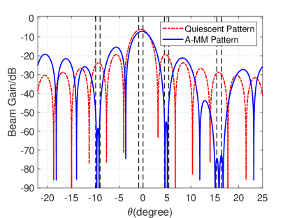
First we compare the beam pattern of the A-MM scheme and the quiescent beam pattern that is essentially the initial beam pattern without nulling. We assume that the BS employs a half-wavelength spaced ULA with NBS=128subscript𝑁BS128N_{\rm BS}=128 antennas and NRF=4subscript𝑁RF4N_{\rm RF}=4 RF chains to communicate with K=4𝐾4K=4 single antenna users, where the number of antennas in each subarray is set as Ns=32subscript𝑁s32N_{\rm s}=32. The angle range of each user is set as Ω1=[0.9,0]subscriptΩ1superscript0.9superscript0\Omega_{1}=[-0.9^{\circ},0^{\circ}], Ω2=[4.5,5.4]subscriptΩ2superscript4.5superscript5.4\Omega_{2}=[4.5^{\circ},5.4^{\circ}], Ω3=[9.9,9]subscriptΩ3superscript9.9superscript9\Omega_{3}=[-9.9^{\circ},-9^{\circ}] and Ω4=[15.4,16.3]subscriptΩ4superscript15.4superscript16.3\Omega_{4}=[15.4^{\circ},16.3^{\circ}], respectively. The weighting factor is set to be λ=1000𝜆1000\lambda=1000. Fig. 1 shows the comparison of beam patterns for the first user. It is seen that A-MM forms nulls in desired angle range while preserving the gain in Ω1subscriptΩ1\Omega_{1}, where the nulling depths reach 55.155.1-55.1dB, 58.558.5-58.5dB and 72.772.7-72.7dB in Ω2subscriptΩ2\Omega_{2}, Ω3subscriptΩ3\Omega_{3} and Ω4subscriptΩ4\Omega_{4}, respectively. Therefore, the multiuser interference is effectively mitigated.

Then we compare the proposed P-WMMSE scheme, the A-MM scheme, fully digital beamforming (Fully Digital), HySBD [5] and TSH [4] in terms of sum-rate. We extend HySBD and TSH to the partially-connected structure and further extend TSH to a noisy scenario with imperfect CSI for fair comparisons with the A-MM scheme.

Refer to caption
Figure 2: Sum-rate performance v.s. SNR for different schemes.

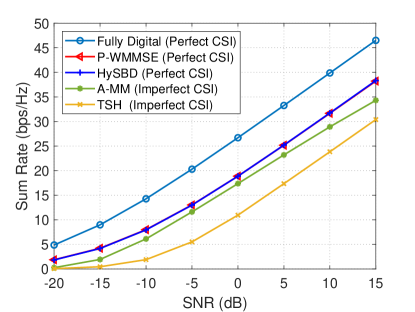
Fig. 2 shows the sum-rate achieved by the five schemes with different SNR. We assume that the BS employs a half-wavelength spaced ULA with NBS=512subscript𝑁BS512N_{\rm BS}=512 antennas and NRF=4subscript𝑁RF4N_{\rm RF}=4 RF chains. The channel between the BS and each user is generated according to (2), where the number of channel paths is set up to Lk=3subscript𝐿𝑘3L_{k}=3 with one line-of-sight (LoS) path and two non-line-of-sight (NLoS) paths. The complex gain of the LoS path is assumed to obey αk,1𝒞𝒩(0,1)similar-tosubscript𝛼𝑘1𝒞𝒩01\alpha_{k,1}\sim\mathcal{CN}(0,1) and that of the NLoS paths obeys αk,l𝒞𝒩(0,0.01)similar-tosubscript𝛼𝑘𝑙𝒞𝒩00.01\alpha_{k,l}\sim\mathcal{CN}(0,0.01). We set λ=1000𝜆1000\lambda=1000 and perform Monte Carlo simulations based on 2000 random channel implementations. As shown in Fig. 2, based on the perfect CSI, the proposed P-WMMSE can achieve the same performance as HySBD, while avoiding SVD for high-dimensional channel matrix 𝑯[𝒉1,,𝒉K]HK×NBS𝑯superscriptsubscript𝒉1subscript𝒉𝐾𝐻superscript𝐾subscript𝑁BS\bm{H}\triangleq[\bm{h}_{1},\cdots,\bm{h}_{K}]^{H}\in\mathbb{C}^{K\times N_{\rm BS}} and therefore reducing the computational complexity. The performance of A-MM reaches 92.0%percent92.092.0\% and 91.1%percent91.191.1\% of that of HySBD with perfect CSI at SNR = 5dB and SNR = 10dB, respectively. Besides of the better performance of A-MM than that of TSH, A-MM does not need to acquire the CSI of effective channels and therefore reduces the pilot overhead and omits the channel estimation therein.

Refer to caption
Figure 3: Sum-rate performance v.s. NBSsubscript𝑁BSN_{\rm BS} for different schemes.

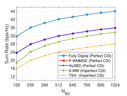
Fig. 3 shows the sum-rate achieved by the five schemes with different NBSsubscript𝑁BSN_{\rm BS}. We set K=4𝐾4K=4 and SNR = 10dB. The sum-rate of the five schemes grows with the increase of NBSsubscript𝑁BSN_{\rm BS}, which is mainly contributed by the gain harvested by large-scale antenna arrays. From the figure, the performance gap between A-MM and the hybrid beamforming schemes based on perfect CSI gets smaller as NBSsubscript𝑁BSN_{\rm BS} increases. The reasons are given as follows. With the increase of NBSsubscript𝑁BSN_{\rm BS}, the array gain and the number of codewords in the codebook increase, which increases the beam resolution and reduces the errors in beam sweeping. Once the width of the mainlobe and sidelobe of the beam becomes narrow, we can reduce the influence of nulling on the mainlobe and the peak beam gain, which improves the signal power received by the user. Therefore, the sum-rate performance can be effectively improved by increasing NBSsubscript𝑁BSN_{\rm BS} if the hardware complexity is supported.

VI Conclusion

In this paper, we have proposed a low-complexity hybrid beamforming scheme based on perfect CSI and an analog-only beamforming scheme based on imperfect CSI for multiuser mmWave massive MIMO systems with partially-connected structure. Future work will be continued with the focus on multiuser beamforming to improve the sum-rate performance for different structures.

References

  • [1] C. Qi, P. Dong, W. Ma, H. Zhang, Z. Zhang, and G. Y. Li, “Acquisition of channel state information for mmWave massive MIMO: Traditional and machine learning-based approaches,” Sci.China Inf. Sci., vol. 64, no. 8, pp. 1–16, Aug. 2021.
  • [2] X. Yu, J.-C. Shen, J. Zhang, and K. B. Letaief, “Alternating minimization algorithms for hybrid precoding in millimeter wave MIMO systems,” IEEE J. Sel. Topics Signal Process., vol. 10, no. 3, pp. 485–500, Apr. 2016.
  • [3] X. Zhao, T. Lin, Y. Zhu, and J. Zhang, “Partially-connected hybrid beamforming for spectral efficiency maximization via a weighted MMSE equivalence,” IEEE Trans. Wireless Commun., vol. 20, no. 12, pp. 8218–8232, Dec. 2021.
  • [4] A. Alkhateeb, G. Leus, and R. W. Heath, “Limited feedback hybrid precoding for multi-user millimeter wave systems,” IEEE Trans. Wireless Commun., vol. 14, no. 11, pp. 6481–6494, Nov. 2015.
  • [5] X. Wu, D. Liu, and F. Yin, “Hybrid beamforming for multi-user massive MIMO systems,” IEEE Trans. Wireless Commun., vol. 66, no. 9, pp. 3879–3891, Sep. 2018.
  • [6] J. Zhan and X. Dong, “Interference cancellation aided hybrid beamforming for mmWave multi-user massive MIMO systems,” IEEE Trans. Veh. Technol., vol. 70, no. 3, pp. 2322–2336, Mar. 2021.
  • [7] Z. Li, C. Qi, and G. Y. Li, “Low-complexity multicast beamforming for millimeter wave communications,” IEEE Trans. Veh. Technol., vol. 69, no. 10, pp. 12 317–12 320, July 2020.
  • [8] X. Sun, C. Qi, and G. Y. Li, “Beam training and allocation for multiuser millimeter wave massive MIMO systems,” IEEE Trans. Wireless Commun., vol. 18, no. 2, pp. 1041–1053, Jan. 2019.
  • [9] Q. Shi, M. Razaviyayn, Z.-Q. Luo, and C. He, “An iteratively weighted MMSE approach to distributed sum-utility maximization for a MIMO interfering broadcast channel,” IEEE Trans. Signal Process., vol. 59, no. 9, pp. 4331–4340, Sep. 2011.
  • [10] M. Sadek, A. Tarighat, and A. H. Sayed, “A leakage-based precoding scheme for downlink multi-user MIMO channels,” IEEE Trans. Wireless Commun., vol. 6, no. 5, pp. 1711–1721, May 2007.
  • [11] J. Song, P. Babu, and D. P. Palomar, “Optimization methods for designing sequences with low autocorrelation sidelobes,” IEEE Trans. Signal Process., vol. 63, no. 15, pp. 3998–4009, Aug. 2015.