Guiding principles for the design of a chemical vapor deposition process for highly crystalline transition metal dichalcogenides
Abstract
Two-dimensional transition metal dichalcogenides (TMDs) for advanced logic transistor technologies are deposited by various modifications of the chemical vapor deposition (CVD) method using a wide variety of precursors. Being a major electrical performance limiter, the TMD crystal grain size strongly differs between the various CVD precursor chemistries from nano- to millimeter-sized crystals. However, it remains unclear how the CVD precursor chemistry affects the nucleation density and resulting TMD crystal grain size. This work postulates guiding principles to design a CVD process for highly crystalline TMD deposition using a quantitative analytical model benchmarked against literature. The TMD nucleation density reduces favorably under low supersaturation conditions, where the metal precursor sorption on the starting surface is reversible and the corresponding metal precursor desorption rate exceeds the overall deposition rate. Such reversible precursor adsorption guarantees efficient long-range gas-phase lateral diffusion of precursor species in addition to short-range surface diffusion, which vitally increases crystal grain size. As such, the proposed model explains the large spread in experimentally observed TMD nucleation densities and crystal grain sizes for state-of-the-art CVD chemistries. Ultimately, it empowers the reader to interpret and modulate precursor adsorption and diffusion reactions through designing CVD precursor chemistries compatible with temperature sensitive application schemes.
I Introduction
I.1 Motivation
Semiconducting two-dimensional (2D) transition metal dichalcogenides (TMDs) with the generic formula MX2, where M is a transition metal and X is a chalcogen, promise to complement silicon (Si) as a channel material by providing better carrier mobility in densely packed ultra-scaled digital circuits [1, 2]. In particular, molybdenum and tungsten disulfide (MoS2 and WS2) have attracted particular research interest due to the combination of sufficiently high carrier mobility [3, 4, 5] and relative stability in the ambient environment [6]. In recent years, the field has advanced from single transistors based on mechanically exfoliated flakes of MoS2 and WS2 [7, 8], to wafer-scale fabrication of logic gates and SRAM [9].
However, many challenges remain before TMD materials can be integrated into sophisticated devices. One of these is the deposition of a high quality TMD monolayer (ML) on 300 mm wafers, which is essential for the envisioned industrial applications. Bulk crystals of MoS2 and WS2 cannot be grown from the melt as these materials decompose at temperatures well below the melting point. In the absence of a native single-crystal substrate, MoS2 and WS2 polycrystalline layers are typically deposited from vapor phase on non-native crystalline or amorphous substrate.
Crystal grain boundaries in TMD material remain a key intrinsic material defect type limiting the TMD electrical performance in semiconductor devices [10, 11]. Such intergranular boundaries are formed by the coalescence of individual crystalline TMD nuclei during the deposition process. Thus, it is possible to increase the grain size and proportionally decrease the density of intergrain defects by decreasing the TMD nucleation density. Therefore, one of the key requirements for a TMD deposition process is the ability to control the nucleation density in order to reduce the density of defects that limit the electrical device performance.
Here, the TMD nucleation density refers to the saturated nucleus density, that is, the number of TMD nuclei deposited per unit of starting surface area during the steady-state growth regime after the saturation of the nucleation process, but before the coalescence [12]. This parameter can be obtained by the usual microscopic examination of the surface and is an approximation of the average crystal grain size of a fully coalesced TMD monolayer.
The degree of alignment of individual TMD nuclei is another parameter that affects intergranular defect density. Defect density decreases when individual nuclei start to align, for example, when deposited epitaxially on a crystalline substrate [13]. In this paper, however, we focus on the physicochemical mechanisms that determine the average crystal grain size, leaving out of scope the influence of the substrate surface topography on the degree of crystal grain alignment.
I.2 Large spread in TMD nucleation densities and crystal grain sizes for state-of-the-art CVD chemistries: literature experimental data

The reported nucleation densities of and [14, 15, 16, 18, 19, 20, 21, 22, 17] vary widely by at about eight orders of magnitude, from to , between the different CVD precursor chemistries, as shown in Figure 1. Although, for a given deposition process the TMD nucleation density generally decreases with increasing deposition temperature, the precursor type may have a more significant effect.
Indeed, certain CVD methods described in literature yield nanocrystalline monolayers of and with nucleation densities ranging from to regardless of the starting surface (e.g., sapphire crystal or amorphous silica dielectric). These include CVD from metal oxide and elemental sulfur precursors [18], CVD from metal-organic and sulfur hydride precursors (MOCVD) [23, 24, 25, 26, 14, 27, 28, 15, 29, 30, 31, 32, 33, 34], and CVD from metal halide and sulfur hydride precursors including metal chloride [35, 36, 37, 38, 39, 16, 40], oxychloride [41], and fluoride compounds [42, 43, 17].
In contrast, iodine-assisted chemical vapor transport (CVT) exhibits TMD nucleation density below even at deposition temperatures as low as 300℃ [21]. Water-assisted CVT also reduces the nucleation density below , but only at deposition temperatures above 800℃ [44, 45].
In addition, multiple works report the reduction of nucleation density by introducing co-reactants [46]. For example, the introduction of alkali metal halide salts [22, 14, 47] or molecular oxygen [18], into the metal-oxide CVD environment allows to reduce the nucleation density to and yield millimeter-scale crystals. Alternatively, co-injection of water vapor in excess of the metal precursor reduces the TMD nucleation density in metal-oxide CVD [48] and MOCVD [49, 32].
Generalized guiding principles that could explain this wide range of TMD nucleation densities and resulting crystal grain size are still lacking in the literature. Theoretical and experimental studies of the early stages of thin film formation indicate that the saturated nucleation density is determined by multiple process parameters, including supersaturation, rates of adsorption, desorption, and surface chemical reactions, as well as depletion of the precursor concentration around growing nuclei associated with limited surface or gas phase diffusion transport [50, 12]. So far however, it remains unclear which of the aforementioned processes is responsible for the observed significant difference in saturated nucleation density for different TMD deposition methods.
I.3 Growth mechanisms that influence nucleation density and crystal grain size in 2D material deposition
The experimentally observed spread in crystal grain size and nucleation density of and monolayers reflects significant differences in the lateral diffusion length of the metal precursor species, as we will show in this manuscript. Indeed, from classical nucleation theory, the magnitude of the saturated nucleation density is proportional to the mean diffusion length of the precursor species [51].
As noted above, the crystal grain size in a coalesced TMD monolayer depends not only on the density of the nuclei, but also on the degree of their orientation.
If the nuclei are perfectly mutually aligned due to epitaxial interaction with the substrate, such nuclei can coalesce without intergranular boundary formation. In this case, the size of the monocrystalline grains in the coalesced layer is much larger than the distance between the nuclei. A classic example is the homoepitaxial growth of silicon on a dislocation-free substrate, where the grain size can be as large as the substrate diameter.
In the opposite case, the interaction with the substrate is so weak that all the nuclei are randomly oriented and an intergranular boundary is formed between coalescing nuclei. Here the monocrystalline grains in the coalesced film are of the same size as the distance between the nuclei.
The Figure 2 illustrates how the interaction with the substrate and the magnitude of the lateral diffusion length affect the crystallinity for the case of 3D epitaxy of a covalently bonded material, such as silicon, and for the case of 2D growth of van-der-Waals bonded TMD material.
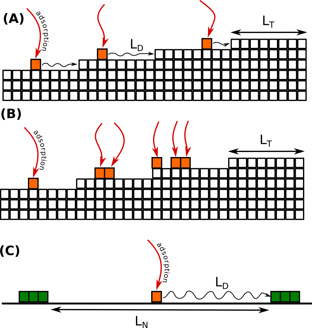
For the conventional epitaxial deposition of a single-crystal 3D material such as Si, the requirements set on the precursor diffusion length are not stringent, as such epitaxial processes rely on crystal lattice matching to the starting surface of a native or non-native single-crystal template by covalent bonding. For the classic example of Si homoepitaxial deposition, the crystallinity and the step-and-terrace structure of the substrate are preserved if the surface diffusion length is comparable to the terrace width
as shown in Figure 2a. Even more, monocrystalline growth of a covalently bonded crystal is possible even when the diffusion length is shorter than the terrace width
as shown in Figure 2b. The step-and-terrace surface structure is lost due to the secondary nucleation on the surface of the terraces, but the single-crystallinity of the growing layer is preserved due to the orienting effect of the template.
The impact of lateral diffusion is significantly stronger in the epitaxy of TMD materials, which is performed on a weakly bound substrate starting from 2D seed crystals (Figure 2c). Due to the van der Waals nature of TMDs, the starting surface does not a priori exert such a strong orienting effect on the adsorbed metal and chalcogen precursor species and the 2D nuclei as in the case of homoepitaxial deposition of covalently bonded materials (e.g., Si). Furthermore, TMD crystals preferentially grow laterally along the crystal edges of a given number of TMD nuclei until the crystals coalesce during the steady-state regime. Hence, the TMD crystal grain size is largely determined by the density of TMD nuclei. The diffusion length should be greater than the inter-nucleus distance
in order to prevent secondary nucleation.
Thus, in van-der-Waals epitaxial growth of 2D materials, the lateral diffusion of precursor species plays a dominant role in defining the crystallinity of the deposited material.
This scientific problem of depositing large 2D crystals can be treated similar to classical area-selective deposition and epitaxial lateral overgrowth studies [52, 53, 54]. Both cases require a complete suppression of deposition over the ‘‘non-growth’’ region of the substrate surface, i.e.:
-
1.
masked region in the case of area-selective deposition;
-
2.
substrate surface between the nuclei in the case of 2D epitaxy.
Also, both cases require efficient lateral transport of precursor species to the ‘‘growth’’ regions of the substrate, i.e.:
-
1.
mask opening in the case of area-selective deposition;
-
2.
TMD nuclei in the case of 2D epitaxy.
The challenging part is that the distance between these ‘‘growth’’ regions can be as large as hundreds of microns [55].
These selective deposition studies have identified two basic mechanisms involved in the lateral transport of precursor species across the starting surface: surface diffusion and gas phase diffusion [52, 56]. Typically, surface diffusion proceeds over submicron distances [52], and slows down exponentially with decreasing deposition temperature [57]. If the diffusive transport of precursor species is predominantly by surface diffusion, the deposition of a highly crystalline material at low temperatures becomes highly challenging.
In contrast, lateral gas-phase diffusion of precursor species allows lateral mass transport over distances beyond tens of microns and is only weakly dependent on the deposition temperature. Hence, lateral gas-phase diffusion is an essential prerequisite for any deposition process when large characteristic distances need to be overcome. Efficient lateral gas-phase diffusion requires the use of highly volatile precursors as shown in [52, 58, 59], but quantitative criteria for the volatility of the precursors are not specified.
Therefore, this paper defines quantitative requirements for the volatility of the deposition reaction components, that allow long-range lateral transport via gas-phase diffusion, and provides an exemplary case for the MoS2 and WS2 deposition.
I.4 Paper outline
This paper describes the general guidelines for designing a TMD CVD process:
-
1.
The nucleation density decreases to and below when lateral gas-phase diffusion of precursor species is possible in addition to surface diffusion.
-
2.
Lateral gas-phase diffusion of the metal precursor is possible when the metal precursor desorption rate exceeds the net deposition rate, i.e., when the metal precursor adsorption becomes reversible.
-
3.
The magnitude of the metal precursor desorption flux is estimated by thermodynamic calculation of the equilibrium partial pressure of the precursor.
The paper consists of three sections. In section II, we demonstrate how to estimate the extent of lateral gas-phase precursor diffusion for any given set of CVD precursors by calculating the precursor desorption rate using chemical equilibrium analysis. Then, in section III, we apply the proposed analytical model to the most commonly reported CVD precursor chemistries for both MoS2 and WS2, and predict the deposition temperature window in which lateral gas-phase diffusion occurs. Finally, in section IV, we compare the predictions of the proposed model with the experimental data from the literature. The comparison confirms that reversible sorption of the metal precursor is a sufficient condition to ensure lateral gas-phase diffusion transport and to deposit millimeter-sized single crystals of TMD.
II The concept: promote reversible metal precursor sorption to enable lateral gas-phase diffusion and increase TMD crystal size
II.1 Lateral gas phase diffusion is possible only if desorption rate is higher than net deposition rate
The TMD deposition process involves the transport of both metal and chalcogen precursors. However, under typical TMD deposition conditions, the chalcogen precursor concentration is several orders of magnitude higher than the metal precursor concentration. As a result, the TMD nucleation and growth processes are limited by the metal precursor. Therefore, in the remainder of this paper, we will focus only on the transport of the metal precursor.
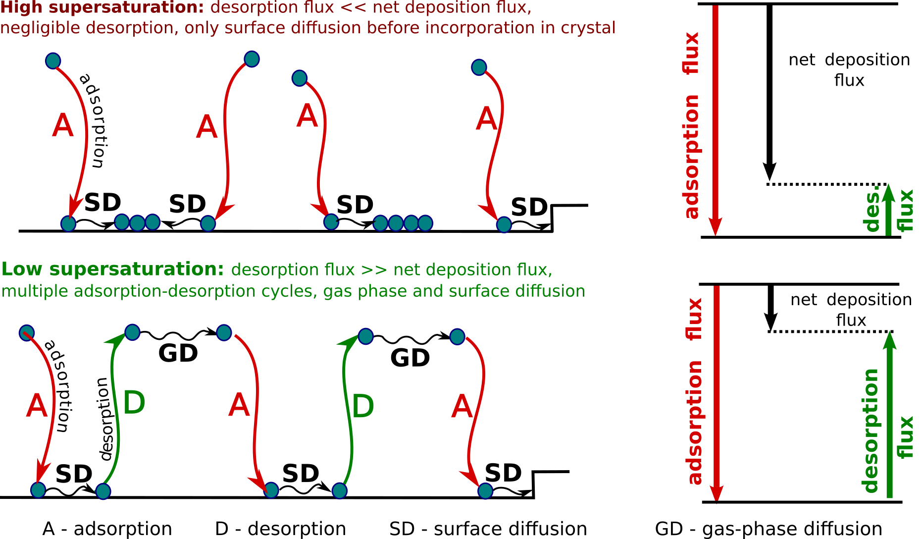
Efficient lateral gas-phase transport relates to the reversibility of metal precursor sorption on the starting surface, as shown schematically in Figure 3.
In the limiting case of negligibly small desorption (Figure 3a), any precursor species colliding with the surface will stick to the surface and never leave it. In this case, the only mechanism for lateral mobility of adsorbed precursor species is surface diffusion.
In the opposite case (Figure 3b), the adsorption and desorption fluxes are nearly equal, so a precursor atom undergoes multiple cycles of adsorption, surface diffusion, desorption, and gas-phase diffusion before being incorporated into the growing crystal. Thus, gas-phase diffusion contributes significantly to the lateral transport when the desorption flux is much larger than the net deposition flux :
| (1) |
II.2 What mechanisms control the desorption rate?
Let’s consider how to design a deposition process that satisfies this condition.
This section examines two limiting cases:
-
1.
deposition rate is limited by the kinetics of the surface reactions;
-
2.
deposition process has infinitely fast surface kinetics.
In the limiting case of surface-kinetics-limited deposition, the partial pressure of the metal precursor at the substrate surface is equal to the initial partial pressure of the metal precursor :
| (2) |
In this case, the net deposition flux is, by definition, much smaller than the adsorption and desorption fluxes, which can be calculated using the Hertz-Knudsen equation [50]:
| (3) |
where is mass of metal precursor specie, is temperature, and is Boltzmann constant.
In the opposite case of infinitely fast surface reaction kinetics, the deposition reaction at the substrate surface is close to equilibrium, and the metal precursor partial pressure is close to the equilibrium value :
| (4) |
As a result, the gas mixture near the surface is significantly depleted of metal precursor and the net condensation flux is determined by the diffusion through the boundary layer [60]:
| (5) |
where is the gas phase diffusion coefficient of the metal precursor species, and is the boundary layer thickness. The metal precursor desorption flux is proportional to :
| (6) |
In all intermediate cases, the actual metal precursor desorption flux is in the range from to :
| (7) |
Now, based on the Equation 7, there are two opposing approaches to deliberately increase the metal precursor desorption flux:
The first approach is to keep the surface reaction away from the reaction equilibrium. The further away from equilibrium the surface reaction is, the higher the and thus the metal precursor desorption flux becomes. Ultimately, the metal precursor desorption flux can be increased up to according to Equation 3. This can be achieved, for example, by lowering the deposition temperature in order to slow down the rate of the surface reaction.
Another way to slow down the deposition kinetics is to reduce the nucleation rate of TMD crystals on the substrate by reducing supersaturation. For example, if the precursor supersaturation corresponds to the Ostwald-Meyers metastable region, the nucleation will be completely inhibited. In the absence of pre-existing ‘‘seed’’ crystals the net deposition rate is zero.
In the second approach, the surface reaction proceeds close to equilibrium so that the metal precursor desorption flux is proportional the equilibrium metal precursor pressure (Equation 6). The magnitude of the equilibrium pressure for a given precursor can be controlled not only by the deposition temperature, but also by the composition of the gas mixture. This provides more degrees of freedom in the design of the deposition process. Following Eqs. 1 and 6 we can estimate the range of metal precursor equilibrium pressures at which the gas phase lateral diffusion transport is activated for a given deposition rate:
| (8) |
In this paper, we will focus on the second approach, as low supersaturation usually favors the growth of pristine crystals.
III Type of CVD precursor couple determines equilibrium metal precursor desorption rate
III.1 Calculating equilibrium metal precursor desorption flux
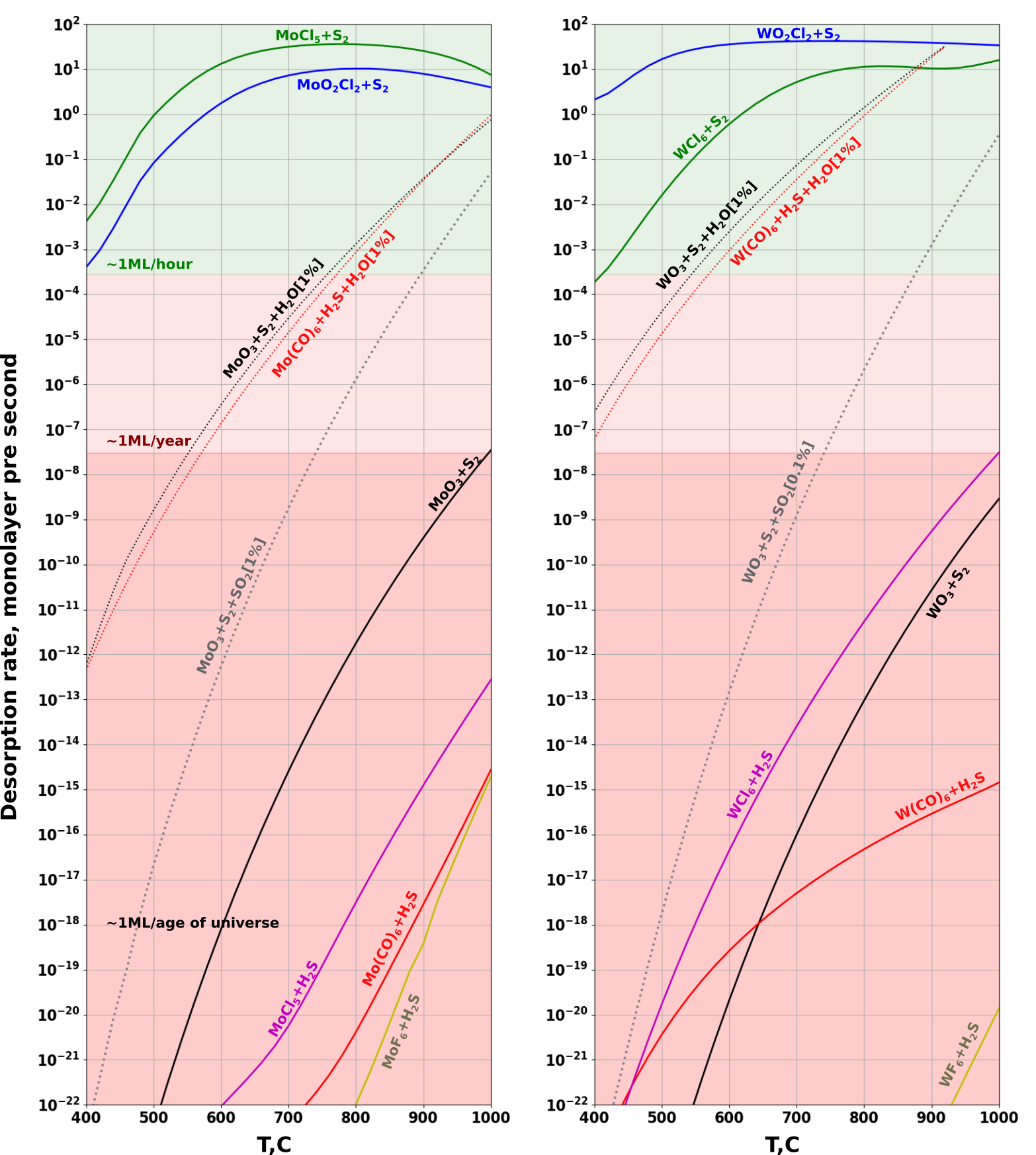
Next, the values of the equilibrium metal precursor desorption flux are calculated for several common deposition methods (Figure 4). The details of the calculation procedure are given in section VI.2. All calculations assume a metal precursor molar concentration of , a sulfur precursor molar concentration of , and a total pressure of 1 atm, that is, the conditions that are representative of a typical TMD CVD process.
III.2 TMD deposition methods demonstrating high equilibrium metal precursor desorption rate
The deposition of MoS2 and WS2 from a metal halide and elemental sulfur proceeds through a group of deposition reactions
| (9) |
and
| (10) |
respectively, where the aggregate state of the substance is indicated by a superscript: for solid and for gas. This system exhibits an equilibrium metal precursor desorption rate exceeding 1 monolayer (ML) per second at deposition temperatures higher than 500℃ for MoS2 deposition and 600℃ for WS2 deposition.
Similarly, when employing a metal oxyhalide precursor instead of a metal halide precursor in combination with elemental sulfur, the overall deposition proceeds according to reactions
| (11) |
and
| (12) |
and the equilibrium metal precursor desorption rate exceeds 1 ML per second at deposition temperatures above 600℃ for MoS2 and over the entire deposition temperature window studied for WS2.
III.3 TMD deposition methods demonstrating negligibly low equilibrium metal precursor desorption rate
In contrast, CVD of MoS2 and WS2 from a metal-organic or metal oxide precursor, regardless of the sulfur precursor type, as well as CVD from a metal halide and sulfur hydride exhibit negligibly low equilibrium metal precursor desorption rates, i.e., less than 1ML/year at deposition temperatures up to 1000℃. However, all of these deposition chemistries are highly sensitive to the injection of additives such as molecular oxygen, water, and alkali metal halides, as discussed in the section III.4.
III.4 Additives, that increase equilibrium desorption rate
The introduction of certain additives, such as alkali metal halides, molecular oxygen, or water vapor, significantly reduces the TMD nucleation rate and thus increases the crystal grain size. Here we categorize two types of such additives:
-
1.
gaseous by-products of the deposition reaction
-
2.
co-reactants that react with the metal precursor.
Gaseous by-products of the TMD deposition reaction
This type of additive does not alter the deposition reaction, but rather shifts the equilibrium of the deposition reaction toward the side of the reactants (i.e., away from the reaction products). An example of such an additive is sulfur dioxide (), which is produced during metal oxide CVD.
Co-reactants
These substances react with the metal precursor to form a more volatile metal compound. In this case, TMD deposition occurs via a different deposition reaction, which has a higher equilibrium metal precursor partial pressure and thus a higher equilibrium desorption rate. Typical examples of such co-reactants are halogen-based compounds (e.g., NaCl) and water vapor. These co-reactants are co-injected with the carrier gas during metal-oxide or metal-organic CVD.
Note that a significant portion of the literature is devoted to vapor-liquid-solid (VLS) growth on substrates containing a predetermined amount of condensed alkali metal halide compounds [61]. However, this interesting approach is beyond the scope of the present research, since the transfer of the precursor to the growth front occurs in the condensed phase, and not by surface or gas-phase diffusion.
III.4.1 Sulfur dioxide as a by-product during metal oxide CVD
Sulfur dioxide () forms as a by-product during the CVD of MoS2 and WS2 from a metal oxide and elemental sulfur precursor, according to the overall deposition reactions (Eqs. 13 and 14).
| (13) |
| (14) |
Thus, intentional co-injection of shifts the reaction equilibrium to the left-hand side (i.e., the side of the reactants), thereby increasing the equilibrium partial pressure of the metal oxide precursor proportional to:
For example, the addition of 1% molar percent of increases the equilibrium metal oxide precursor desorption rate for both Mo and W by six orders of magnitude (Figure 4).
To the best of our knowledge, experiments in which a fixed and controlled amount of gaseous is injected intentionally and simultaneously into the CVD gas mixture have not been reported in literature. However, forms as a by-product during the metal oxide CVD process, for example when sulfur reacts with metal oxide precursor or gaseous molecular oxygen via reactions 13 and 14:
- •
-
•
Another way to produce SO2 is to add molecular oxygen to the carrier gas [18], where the elemental sulfur reacts with the oxygen to produce sulfur dioxide:
III.4.2 Alkali metal halide as a co-reactant during metal oxide CVD
When alkali metal halides are added to the crucible containing the metal oxide precursor, both compounds react producing a more volatile metal oxychloride [64] according to reactions:
| (15) |
III.4.3 Water-assisted metal oxide and metal-organic CVD
Co-injection of water vapor during either metal oxide or metal-organic CVD affects the TMD deposition process in two different ways.
First, water reacts with the initial metal precursor to form a more volatile metal compound, such as a metal hydroxide. Such volatile hydroxides of molybdenum (MoH2O4) and tungsten (WH2O4) form in presence of water vapor by reaction with metal [65, 66, 67],metal oxide [68, 69], metal chalcogenide [44, 45], or metal-organic precursor [49, 32].
Second, water alters the reaction equilibrium of the TMD deposition reaction as it is one of the gaseous reaction products of the reaction between MoH2O4 and H2S precursors according to 17.
| (17) |
Adding 1% volume percent of water vapor during metal oxide or metal-organic CVD increases to 1ML/s at deposition temperatures above 1000℃ for MoS2 and above 800℃ for WS2 deposition, respectively (Figure 4).
IV Benchmarking the model with experimental data
IV.1 Comparison to published deposition methods
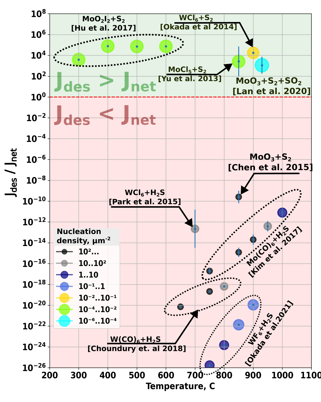
This last section compares the above calculated values of the equilibrium metal precursor desorption flux with the available experimental data on the TMD nucleation density and crystal grain size for the most reported TMD deposition methods [19, 20, 18, 16, 21, 14, 15, 22, 17].
For each literature source, the value of was estimated, using the experimental details provided by the respective authors: this includes deposition temperature, total pressure, initial composition of the precursor mixture supplied to the reactor, and resulting TMD deposition rate. This comparison with the literature reveals how the TMD nucleation density, and hence the crystal grain size, depends on the deposition temperature and on the estimated ratio of metal precursor desorption flux to net deposition flux (Figure 5).
Indeed, when the condition is satisfied, the TMD nucleation density ranges from [20] down to [22] and the crystal grain size increases above [22] for metal halide[19, 20], metal oxyhalide [21] and metal oxide CVD [22]. In the latter case, however, SO2 is formed as a reaction by-product from the reaction of the metal oxide with the sulfur precursor, as described in section III.4.1.
In contrast, for deposition methods where the equilibrium metal precursor desorption flux is negligibly small, the TMD nucleation density remains high between and , and the representative crystal grain size falls into the submicron range. As detailed in section III, these deposition methods include MOCVD [14, 15], CVD from metal halide and sulfur hydride precursors [16, 17] and metal oxide CVD [18].
IV.2 Limits of applicability: how to determine true value of metal precursor desorption rate?
IV.2.1 Complementing model predictions with experimental data
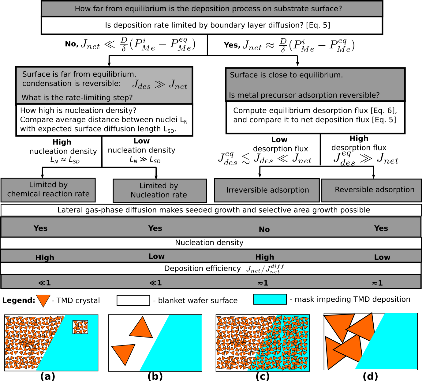
The equilibrium desorption flux calculated using Equation. 6 represents the lower limit of the actual desorption flux. The latter can differ significantly from its equilibrium value depending on the rate of surface kinetics. The influence of surface kinetics can be estimated from experimentally determined deposition rates and nucleation densities as summarized in Figure 6.
The type of rate-limiting process can be identified by measuring the TMD deposition rate and comparing it with the value of the deposition rate in the diffusion boundary layer limit calculated by Equation 5:
An assumption about the nature of the limiting stage of the kinetics can be made based on the measured nucleation density of the deposit and a thermochemical estimate of the supersaturation value.
Below we consider typical cases of deposition processes limited by surface kinetics and by boundary-layer diffusion.
IV.2.2 Surface kinetics limited deposition
When the deposition rate is limited by surface kinetics, the gas phase is not depleted of metal precursor (Equation 2). As a result, the lateral gas-phase diffusion mechanism is active since the condition for reversible sorption (Equation 1) is satisfied. The deposition reaction at the surface is far from equilibrium under these conditions.
The process limiting the deposition rate can be either an elementary microscopic process, such as a chemical reaction, or a nucleation phenomenon. These cases can be distinguished by the observed nucleation density:
-
1.
Deposition limited by the surface chemical reaction rate under high supersaturation conditions will exhibit a high nucleation density,resulting in a polycrystalline structure of the deposited TMD material (Figure 6a). At the same time, efficient long-range lateral transport via gas-phase diffusion can proceed since the adsorption is reversible.
The features of this deposition regime can be illustrated by the area-selective deposition experiments. On the one hand, area-selective deposition is achieved despite high supersaturation when the deposition reaction is suppressed on a certain area of the substrate by applying a mask or surface functionalization [70, 71]. Deposition on masks is suppressed even if the masked areas are much larger than the surface diffusion length. On the other hand, the crystal perfection and purity of the material deposited inside the mask openings are usually poor [72].
-
2.
Deposition limited by the nucleation kinetics can be experimentally identified by the dependence of the deposition rate on the areal density of seed crystals on the substrate surface (Figure 6b). In the Ostwald-Meyers region, the deposition occurs exclusively on the seed crystals present on the substrate surface. The low nucleation density determines the larger achievable size of monocrystalline grains compared to kinetically limited deposition at high supersaturation.
It should be noted that these two cases are not mutually exclusive. For example, if the surface reaction rate is zero, then the nucleation rate is also zero. Consider the opposite case: low supersaturation and therefore low nucleation density. If the total deposition rate is less than the diffusion-limited rate (Equation 5), this indicates the presence of a kinetic constraint on the lateral rate of crystallite growth. One mechanism for such a kinetic limitation may be the limited rate of chemical reaction at the edge of the crystallites.
IV.2.3 Boundary layer diffusion limited deposition
Now consider the limiting case of infinitely fast surface reactions, so that the actual precursor desorption flux is close to its equilibrium value (Figure 6c-d). For this type of processes, the model proposed in this paper is applicable. Let us consider two limiting cases depending on the ratio of the calculated equilibrium desorption flux (Equation 6) to the net deposition rate.
If the equilibrium desorption flux is negligible compared to the deposition rate, then the metal precursor adsorption is irreversible and the crystal grain size is determined solely by the surface diffusion length, which usually ranges from tens of nanometers to several micrometers and depends exponentially on temperature (Figure 6c). Typical examples are MOCVD [14, 15] and chloride-hydride CVD [17].
On the contraty, if the equilibrium metal precursor desorption flux exceeds the net deposition flux, the gas-phase diffusion leads to a significant increase in crystal size, as described in more detail in the previous two sections (Figure 6d). Examples include processes using elemental sulfur and metal halide or oxyhalide precursors [21, 19, 20].
V Conclusions

Lateral gas-phase diffusion is an essential prerequisite to for the formation of highly crystalline TMD monolayers on amorphous substrates. It occurs over a wider deposition temperature range and larger length scales (cm-scale) than surface diffusion, yet its contribution to TMD deposition processes is often overlooked in the literature.
For reversible adsorption and lateral gas-phase diffusion to occur, the equilibrium metal precursor desorption flux should exceed the net deposition flux. Satisfying this singular condition is sufficient, as the actual metal precursor desorption flux is, by definition, always greater than the equilibrium desorption flux, even though the rate of the surface reaction kinetics is not known a priori.
Comparison of the proposed model with experimental data from the literature confirms that the TMD nucleation density decreases and the resulting crystal size increases when the metal precursor adsorption becomes reversible, and thus allowing efficient lateral gas-phase diffusion of the metal precursor.
Metal-halide precursors in combination with elemental sulfur provide the highest metal precursor volatility among commonly used precursor chemistries.
Two mechanisms by which co-reagents improve TMD crystallinity are shown. The first type of co-reagent is a gaseous by-product of the TMD deposition reaction. The second type of co-reagent is a substance that reacts with the metal precursor to form a more volatile metal compound.
VI Methods
VI.1 Estimating reversability of metal precursor adsorption based on thermochemical data
Adsorption is reversible when the metal precursor desorption flux exceeds the net deposition flux (Equation 1). The desorption flux in the process depends on the rate of surface kinetics, and is not known a priori, but it is always greater than the equilibrium desorption flux (Equation 7). Therefore the equilibrium desorption flux (Equation 6) exceeding the net deposition flux represents a sufficient condition for reversible adsorption.
Thus, the adsorption reversibility for a given deposition process can be estimated using the following calculation procedure:
-
1.
Define the process parameters required for the equilibrium calculation: the composition of the precursor mixture at the inlet of the deposition chamber, the pressure and temperature of the process.
-
2.
Identify potential deposition reaction products to be considered in the equilibrium calculation.
- 3.
-
4.
Calculate the net deposition flux for the case of a boundary layer diffusion-limited deposition using Equation 5.
-
5.
Calculate the equilibrium desorption flux using Equation 6.
-
6.
Check if .
Several numerical examples illustrating this computational procedure are given below in the section VI.3.
VI.2 Thermodynamic equilibrium calculation
The equilibrium vapor pressures of the reagents involved in the deposition process are evaluated by numerical minimization of the Gibbs free energy using a hierarchical algorithm [73, 74, 75], while the equilibrium desorption fluxes are calculated through Equation 6. Thermochemical properties of substances from [79, 80, 81, 82] are used. The substances considered in the calculation are listed below, where superscript indicates the phase of the substance: s – solid, l – liquid, and g – gaseous:
Molybdenum
, , , , , , , , , , , , , , , , , , , , , , , , , , , , , , , , , , , , , , , , ,
Tungsten
, , , , , , , , , , , , , , , , , , , , , , , , , , , , , , , , , , , , , , , , ,
Sulfur
, , , , , , , , , , , , , , , , , , , , , , , , , , , , , , ,
Chlorine and fluorine
, , , , , , , , , , , , , ,
Carbon
, , , , , , , , , ,
Oxygen and hydrogen
, , , , , , , , .
VI.3 Numerical example of calculating the metal precursor desorption flux for CVD from metal oxide and elemental sulfur precursors.
In this section, we will show how to choose the parameters of the deposition process to ensure lateral gas-phase diffusion based on equilibrium calculations.
As an illustration, we provide numerical examples of the calculation of the equilibrium desorption rate for the case of MoS2 deposition using molybdenum oxide and elemental sulfur precursors.
Example 1: Metal precursor desorption rate in CVD using MoO3 and S2 precursors
| T,℃ | , kJ/mol | |||||
|---|---|---|---|---|---|---|
| K | ||||||
| 400 | 562 | 31 | 330 | 471 | 421 | |
| 500 | 596 | 57 | 343 | 500 | 398 | |
| 600 | 631 | 83 | 356 | 530 | 375 | |
| 700 | 666 | 110 | 370 | 560 | 352 | |
| 800 | 703 | 137 | 386 | 591 | 329 | |
| 900 | 740 | 165 | 402 | 622 | 306 | |
| 1000 | 778 | 192 | 418 | 653 | 284 | |
Let’s consider a process with the following parameters:
-
•
Process pressure is 1 bar (100kPa), process temperature is 900℃, carrier gas is an inert gas.
-
•
Initial precursor partial pressures are atm, atm, =0 atm
For simplicity, we assume that the deposition process involves only 4 species: , , , and , connected via single deposition reaction (Equation 13):
| (18) |
where reaction quotient is limited by the amount of precursor present in the deficiency:
| (19) |
The thermochemical properties of the species involved in this reaction are given in Table 1.
The equilibrium partial pressures of , , and can be found by solving equation
| (20) |
against . However, for this particular case, it can be simplified by noting that the equilibrium is shifted to the right, so that , and that . Under this assumption
Substituting numerical values of and into Equation 22 gives:
Example 2: Increasing desorption rate by co-injecting reaction products
The equilibrium pressure of molybdenum oxide can be increased by increasing concentration of in the gas mixture. Consider an increase in the equilibrium pressure of in the case where the concentration of in the gas mixture is 10%. The initial precursor partial pressures are atm, atm, =0.1 atm.
Assuming that
Equation 20 is approximated as:
| (24) |
that gives significantly higher equilibrium vapor pressure and desorption rate:
| (25) |
so condition 1 is satisfied for deposition rate 1 monolayer per 2 minutes.
Example 3: Multicomponent equilibrium analysis
| Elements | Substances |
|---|---|
| Molybdenum | |
| Sulfur | , , , , , , , |
| Oxygen | , , |
| Molybdenum oxides | , , , , , , , , , |
| Molybdenum sulfides | , |
| Sulfur oxides | , , , |
The accuracy of thermodynamic equilibrium analysis depends on whether all significant substances are included in the calculation. Simplified calculations involving only one basic chemical reaction, such as those discussed above, are intuitive, but if the substances involved in them are chosen incorrectly, they will give erroneous results.
Numerical calculation of the equilibrium composition of the multicomponent MoS2 CVD from and precursors was performed by Gibbs energy minimization. All substances listed in the Table 2 are considered. The resulting values of the equilibrium pressures of the components are shown in Figure 7b,d.
As can be seen from Figures 7a and 7b, the results obtained in the single-reaction approximation (Equation 23) taking into account only one gaseous molybdenum compound - are close to the results obtained by the multicomponent calculation, since the equilibrium pressure of other gaseous molybdenum compounds is negligible compared to the equilibrium pressure of .
At the same time, the results of the calculation of the system with the addition of , shown in Figure 7c and Figure 7d, show significant differences compared to the single-reaction approximation:
-
1.
equilibrium desorption rate is several times higher than predicted by the simplified calculation using the Equation 25, since, in addition to , other molecules, including and , are present in comparable amounts.
-
2.
equilibrium composition of the condensed phase changes at 917℃: is the equilibrium condensed molybdenum compound at temperatures below 917℃, while is formed in equilibrium at temperatures above 917℃.
This emphasizes the importance of multicomponent analysis, since ignoring molecules can lead to a significant distortion of the results.
VII Acknowledgments
The authors gratefully acknowledge the funding from the imec IIAP core CMOS programs and the European Union’s Graphene Flagship grant agreement No 952792.
References
- [1] Joshua A Robinson. Perspective: 2d for beyond cmos. Apl Materials, 6(5):058202, 2018.
- [2] Shuiyuan Wang, Xiaoxian Liu, and Peng Zhou. The road for 2d semiconductors in the silicon age. Advanced Materials, page 2106886, 2021.
- [3] Hennrik Schmidt, Francesco Giustiniano, and Goki Eda. Electronic transport properties of transition metal dichalcogenide field-effect devices: surface and interface effects. Chemical Society Reviews, 44(21):7715–7736, 2015.
- [4] Song-Lin Li, Kazuhito Tsukagoshi, Emanuele Orgiu, and Paolo Samorì. Charge transport and mobility engineering in two-dimensional transition metal chalcogenide semiconductors. Chemical Society Reviews, 45(1):118–151, 2016.
- [5] Sajedeh Manzeli, Dmitry Ovchinnikov, Diego Pasquier, Oleg V Yazyev, and Andras Kis. 2d transition metal dichalcogenides. Nature Reviews Materials, 2(8):1–15, 2017.
- [6] Junqiang Yang, Xiaochi Liu, Qianli Dong, Yaqi Shen, Yuchuan Pan, Zhongwang Wang, Kui Tang, Xianfu Dai, Rongqi Wu, Yuanyuan Jin, et al. Oxidations of two-dimensional semiconductors: Fundamentals and applications. Chinese Chemical Letters, 33(1):177–185, 2022.
- [7] Branimir Radisavljevic, Aleksandra Radenovic, Jacopo Brivio, Valentina Giacometti, and Andras Kis. Single-layer mos2 transistors. Nature nanotechnology, 6(3):147–150, 2011.
- [8] Thanasis Georgiou, Rashid Jalil, Branson D Belle, Liam Britnell, Roman V Gorbachev, Sergey V Morozov, Yong-Jin Kim, Ali Gholinia, Sarah J Haigh, Oleg Makarovsky, et al. Vertical field-effect transistor based on graphene–ws2 heterostructures for flexible and transparent electronics. Nature nanotechnology, 8(2):100–103, 2013.
- [9] Na Li, Qinqin Wang, Cheng Shen, Zheng Wei, Hua Yu, Jing Zhao, Xiaobo Lu, Guole Wang, Congli He, Li Xie, et al. Large-scale flexible and transparent electronics based on monolayer molybdenum disulfide field-effect transistors. Nature Electronics, 3(11):711–717, 2020.
- [10] Thuc Hue Ly, David J Perello, Jiong Zhao, Qingming Deng, Hyun Kim, Gang Hee Han, Sang Hoon Chae, Hye Yun Jeong, and Young Hee Lee. Misorientation-angle-dependent electrical transport across molybdenum disulfide grain boundaries. Nature communications, 7(1):1–7, 2016.
- [11] Jae-Keun Kim, Younggul Song, Tae-Young Kim, Kyungjune Cho, Jinsu Pak, Barbara Yuri Choi, Jiwon Shin, Seungjun Chung, and Takhee Lee. Analysis of noise generation and electric conduction at grain boundaries in cvd-grown mos2 field effect transistors. Nanotechnology, 28(47):47LT01, 2017.
- [12] KJ Routledge and MJ Stowell. Nucleation kinetics in thin film growth. i. computer simulation of nucleation and growth behaviour. Thin Solid Films, 6(6):407–421, 1970.
- [13] Lisanne Peters, Cormac Ó Coileáin, Patryk Dluzynski, Rita Siris, Georg S Duesberg, and Niall McEvoy. Directing the morphology of chemical vapor deposition-grown mos2 on sapphire by crystal plane selection. physica status solidi (a), 217(15):2000073, 2020.
- [14] HoKwon Kim, Dmitry Ovchinnikov, Davide Deiana, Dmitrii Unuchek, and Andras Kis. Suppressing nucleation in metal–organic chemical vapor deposition of mos2 monolayers by alkali metal halides. Nano letters, 17(8):5056–5063, 2017.
- [15] Tanushree H Choudhury, Hamed Simchi, Raphael Boichot, Mikhail Chubarov, Suzanne E Mohney, and Joan M Redwing. Chalcogen precursor effect on cold-wall gas-source chemical vapor deposition growth of ws2. Crystal Growth & Design, 18(8):4357–4364, 2018.
- [16] Jusang Park, Wonseon Lee, Taejin Choi, Sung-Hwan Hwang, Jae Min Myoung, Jae-Hoon Jung, Soo-Hyun Kim, and Hyungjun Kim. Layer-modulated synthesis of uniform tungsten disulfide nanosheet using gas-phase precursors. Nanoscale, 7(4):1308–1313, 2015.
- [17] Mitsuhiro Okada, Naoya Okada, Wen-Hsin Chang, Tetsuo Shimizu, Toshitaka Kubo, Masatou Ishihara, and Toshifumi Irisawa. Micrometer-scale ws2 atomic layers grown by alkali metal free gas-source chemical vapor deposition with h2s and wf6 precursors. Japanese Journal of Applied Physics, 60(SB):SBBH09, 2021.
- [18] Wei Chen, Jing Zhao, Jing Zhang, Lin Gu, Zhenzhong Yang, Xiaomin Li, Hua Yu, Xuetao Zhu, Rong Yang, Dongxia Shi, Xuechun Lin, Jiandong Guo, Xuedong Bai, and Guangyu Zhang. Oxygen-assisted chemical vapor deposition growth of large single-crystal and high-quality monolayer mos2. Journal of the American Chemical Society, 137(50):15632–15635, 2015. PMID: 26623946.
- [19] Yifei Yu, Chun Li, Yi Liu, Liqin Su, Yong Zhang, and Linyou Cao. Controlled scalable synthesis of uniform, high-quality monolayer and few-layer mos2 films. Scientific reports, 3(1):1–6, 2013.
- [20] Mitsuhiro Okada, Takumi Sawazaki, Kenji Watanabe, Takashi Taniguch, Hiroki Hibino, Hisanori Shinohara, and Ryo Kitaura. Direct chemical vapor deposition growth of ws2 atomic layers on hexagonal boron nitride. ACS nano, 8(8):8273–8277, 2014.
- [21] Dake Hu, Guanchen Xu, Lei Xing, Xingxu Yan, Jingyi Wang, Jingying Zheng, Zhixing Lu, Peng Wang, Xiaoqing Pan, and Liying Jiao. Two-dimensional semiconductors grown by chemical vapor transport. Angewandte Chemie International Edition, 56(13):3611–3615, 2017.
- [22] Feifei Lan, Ruixia Yang, Song Hao, Baozeng Zhou, Kewei Sun, Hongjuan Cheng, Song Zhang, Lujie Li, and Lei Jin. Controllable synthesis of millimeter-size single crystal ws2. Applied Surface Science, 504:144378, 2020.
- [23] J.-W. Chung, Z.R. Dai, and F.S. Ohuchi. WS2 thin films by metal organic chemical vapor deposition. Journal of Crystal Growth, 186(1):137–150, mar 1998.
- [24] Claire J Carmalt, Ivan P Parkin, and Emily S Peters. Atmospheric pressure chemical vapour deposition of ws2 thin films on glass. Polyhedron, 22(11):1499–1505, 2003.
- [25] Jihun Mun, Yeongseok Kim, Il-Suk Kang, Sung Kyu Lim, Sang Jun Lee, Jeong Won Kim, Hyun Min Park, Taesung Kim, and Sang-Woo Kang. Low-temperature growth of layered molybdenum disulphide with controlled clusters. Scientific reports, 6(1):21854, 2016.
- [26] Stéphane Cadot, Olivier Renault, Denis Rouchon, Denis Mariolle, Emmanuel Nolot, Chloé Thieuleux, Laurent Veyre, Hanako Okuno, François Martin, and Elsje Alessandra Quadrelli. Low-temperature and scalable cvd route to ws2 monolayers on sio2/si substrates. Journal of Vacuum Science & Technology A, 35(6):061502, 2017.
- [27] TaeWan Kim, Jihun Mun, Hyeji Park, DaeHwa Joung, Mangesh Diware, Chegal Won, Jonghoo Park, Soo-Hwan Jeong, and Sang-Woo Kang. Wafer-scale production of highly uniform two-dimensional mos2 by metal-organic chemical vapor deposition. Nanotechnology, 28(18):18LT01, 2017.
- [28] Daniele Chiappe, Jonathan Ludwig, Alessandra Leonhardt, Salim El Kazzi, Ankit Nalin Mehta, Thomas Nuytten, Umberto Celano, Surajit Sutar, Geoffrey Pourtois, Matty Caymax, et al. Layer-controlled epitaxy of 2d semiconductors: bridging nanoscale phenomena to wafer-scale uniformity. Nanotechnology, 29(42):425602, 2018.
- [29] Stefan Cwik, Dariusz Mitoraj, Oliver Mendoza Reyes, Detlef Rogalla, Daniel Peeters, Jiyeon Kim, Hanno Maria Schütz, Claudia Bock, Radim Beranek, and Anjana Devi. Direct growth of mos2 and ws2 layers by metal organic chemical vapor deposition. Advanced Materials Interfaces, 5(16):1800140, 2018.
- [30] A Grundmann, D Andrzejewski, T Kümmell, G Bacher, M Heuken, H Kalisch, and A Vescan. H 2 s-free metal-organic vapor phase epitaxy of coalesced 2d ws 2 layers on sapphire. MRS Advances, 4:593–599, 2019.
- [31] Nitin Babu Shinde, Bellarmine Francis, MS Ramachandra Rao, Beo Deul Ryu, S Chandramohan, and Senthil Kumar Eswaran. Rapid wafer-scale fabrication with layer-by-layer thickness control of atomically thin mos2 films using gas-phase chemical vapor deposition. APL Materials, 7(8):081113, 2019.
- [32] Assael Cohen, Avinash Patsha, Pranab K Mohapatra, Miri Kazes, Kamalakannan Ranganathan, Lothar Houben, Dan Oron, and Ariel Ismach. Growth-etch metal–organic chemical vapor deposition approach of ws2 atomic layers. ACS nano, 15(1):526–538, 2020.
- [33] Minsu Seol, Min-Hyun Lee, Haeryong Kim, Keun Wook Shin, Yeonchoo Cho, Insu Jeon, Myoungho Jeong, Hyung-Ik Lee, Jiwoong Park, and Hyeon-Jin Shin. High-throughput growth of wafer-scale monolayer transition metal dichalcogenide via vertical ostwald ripening. Advanced Materials, 32(42):2003542, 2020.
- [34] Christian M Schaefer, Jose M Caicedo Roque, Guillaume Sauthier, Jessica Bousquet, Clement Hebert, Justin R Sperling, Amador Perez-Tomas, Jose Santiso, Elena del Corro, and Jose A Garrido. Carbon incorporation in mocvd of mos2 thin films grown from an organosulfide precursor. Chemistry of Materials, 33(12):4474–4487, 2021.
- [35] Henryk Arctowski. Uber die doppelte Umsetzung bei gasformigen Korpern. Zeitschrift fur anorganische Chemie, 8(1):213–223, 1895.
- [36] Nobuyuki Imanishi, Kiyoshi Kanamura, and Zen ichiro Takehara. Synthesis of MoS2 Thin Film by Chemical Vapor Deposition Method and Discharge Characteristics as a Cathode of the Lithium Secondary Battery. Journal of The Electrochemical Society, 139(8):2082–2087, aug 1992.
- [37] Keune, H., Lacom, W., Rossi, F., Stoffels, E., Stoffels, W. W., and Wahl, G. Formation and deposition of MoS2-nanoparticles. J. Phys. IV France, 10:Pr2–19–Pr2–26, 2000.
- [38] A Margolin, FL Deepak, Ronit Popovitz-Biro, M Bar-Sadan, Y Feldman, and R Tenne. Fullerene-like ws2 nanoparticles and nanotubes by the vapor-phase synthesis of wcln and h2s. Nanotechnology, 19(9):095601, 2008.
- [39] Chung-Che Huang, Feras Al-Saab, Yudong Wang, Jun-Yu Ou, John C Walker, Shuncai Wang, Behrad Gholipour, Robert E Simpson, and Daniel W Hewak. Scalable high-mobility mos 2 thin films fabricated by an atmospheric pressure chemical vapor deposition process at ambient temperature. Nanoscale, 6(21):12792–12797, 2014.
- [40] William R Campbell, Francesco Reale, Ravi Sundaram, and Simon J Bending. Optimisation of processing conditions during cvd growth of 2d ws2 films from a chloride precursor. Journal of Materials Science, pages 1–15, 2022.
- [41] Jee Hyeon Kim, Chaehyeon Ahn, Jong-Guk Ahn, Younghee Park, Soyoung Kim, Daehyun Kim, Jaeyoon Baik, Jaehoon Jung, and Hyunseob Lim. Vapor pressure-controllable molecular inorganic precursors for growth of monolayer ws2: Influence of precursor-substrate interaction on growth thermodynamics. Applied Surface Science, 587:152829, 2022.
- [42] Woo Y. Lee, Theodore M. Besmann, and Michael W. Stott. Preparation of MoS2 thin films by chemical vapor deposition. Journal of Materials Research, 9(6):1474–1483, jun 1994.
- [43] B. Groven, D. Claes, A. Nalin Mehta, H. Bender, W. Vandervorst, M. Heyns, M. Caymax, I. Radu, and A. Delabie. Chemical vapor deposition of monolayer-thin ws2 crystals from the wf6 and h2s precursors at low deposition temperature. The Journal of Chemical Physics, 150(10):104703, 2019.
- [44] Prasana K Sahoo, Shahriar Memaran, Yan Xin, Luis Balicas, and Humberto R Gutiérrez. One-pot growth of two-dimensional lateral heterostructures via sequential edge-epitaxy. Nature, 553(7686):63–67, 2018.
- [45] Yuzhou Zhao and Song Jin. Controllable water vapor assisted chemical vapor transport synthesis of ws2–mos2 heterostructure. ACS Materials Letters, 2(1):42–48, 2019.
- [46] Qing Zhang, Xixi Xiao, Lin Li, Dechao Geng, Wei Chen, and Wenping Hu. Additive-assisted growth of scaled and quality 2d materials. Small, 18(17):2107241, 2022.
- [47] Kibum Kang, Saien Xie, Lujie Huang, Yimo Han, Pinshane Y Huang, Kin Fai Mak, Cheol-Joo Kim, David Muller, and Jiwoong Park. High-mobility three-atom-thick semiconducting films with wafer-scale homogeneity. Nature, 520(7549):656–660, 2015.
- [48] Christoph Kastl, Christopher T Chen, Tevye Kuykendall, Brian Shevitski, Thomas P Darlington, Nicholas J Borys, Andrey Krayev, P James Schuck, Shaul Aloni, and Adam M Schwartzberg. The important role of water in growth of monolayer transition metal dichalcogenides. 2D Materials, 4(2):021024, 2017.
- [49] Soo Ho Choi, Boandoh Stephen, Ji-Hoon Park, Joo Song Lee, Soo Min Kim, Woochul Yang, and Ki Kang Kim. Water-assisted synthesis of molybdenum disulfide film with single organic liquid precursor. Scientific reports, 7(1):1–8, 2017.
- [50] G Pound and J Hirth. Condensation and evaporation, nucleation and growth kinetics. Prog. Mater. Sci, 11, 1963.
- [51] J Bloem. Nucleation in the epitaxial growth of silicon. Journal of Crystal Growth, 38(3):364–366, 1977.
- [52] Ko-ichi Yamaguchi Ko-ichi Yamaguchi and Kotaro Okamoto Kotaro Okamoto. Lateral supply mechanisms in selective metalorganic chemical vapor deposition. Japanese journal of applied physics, 32(4R):1523, 1993.
- [53] Michael E Coltrin and Christine C Mitchell. Mass transport and kinetic limitations in mocvd selective-area growth. Journal of crystal growth, 254(1-2):35–45, 2003.
- [54] Tomonari Shioda, Yuki Tomita, Masakazu Sugiyama, Yukihiro Shimogaki, and Yoshiaki Nakano. Selective area metal–organic vapor phase epitaxy of nitride semiconductors for multicolor emission. IEEE Journal of Selected Topics in Quantum Electronics, 15(4):1053–1065, 2009.
- [55] A Gupta, XW Li, S Guha, and Gang Xiao. Selective-area and lateral overgrowth of chromium dioxide (cro 2) films by chemical vapor deposition. Applied Physics Letters, 75(19):2996–2998, 1999.
- [56] Fredrik Olsson, Tiankai Zhu, Gaël Mion, and Sebastian Lourdudoss. Large mask area effects in selective area growth. Journal of Crystal Growth, 289(1):24–30, 2006.
- [57] AG Naumovets and Yu S Vedula. Surface diffusion of adsorbates. Surface Science Reports, 4(7-8):365–434, 1985.
- [58] DR Bradbury, TI Kamins, and C-W Tsao. Control of lateral epitaxial chemical vapor deposition of silicon over insulators. Journal of applied physics, 55(2):519–523, 1984.
- [59] Tomonobu Tsuchiya. Cl-assisted selective area growth of inp by metalorganic vapor phase epitaxy. Japanese journal of applied physics, 38(2S):1034, 1999.
- [60] DW Shaw. Crystal Growth, volume 1, chapter Mechanisms in Vapour Epitaxy of Semiconductors, pages 1–48. Springer, 1974.
- [61] Chenqi Yu, Pu Chang, Lixiu Guan, and Junguang Tao. Inward growth of monolayer mos2 single crystals from molten na2moo4 droplets. Materials Chemistry and Physics, 240:122203, 2020.
- [62] Yi-Hsien Lee, Xin-Quan Zhang, Wenjing Zhang, Mu-Tung Chang, Cheng-Te Lin, Kai-Di Chang, Ya-Chu Yu, Jacob Tse-Wei Wang, Chia-Seng Chang, Lain-Jong Li, et al. Synthesis of large-area mos2 atomic layers with chemical vapor deposition. Advanced materials, 24(17):2320–2325, 2012.
- [63] Cheol-Min Hyun, Jeong-Hun Choi, Seung Won Lee, Jeong Hwa Park, Kang-Taek Lee, and Ji-Hoon Ahn. Synthesis mechanism of mos2 layered crystals by chemical vapor deposition using moo3 and sulfur powders. Journal of Alloys and Compounds, 765:380–384, 2018.
- [64] DA Johnson, JH Levy, JC Taylor, AB Waugh, and J Brough. Purification of molybdenum: volatilisation processes using moo3. Polyhedron, 1(5):479–482, 1982.
- [65] GR Belton and RL McCarron. The volatilization of tungsten in the presence of water vapor. The Journal of Physical Chemistry, 68(7):1852–1856, 1964.
- [66] GR Belton and AS Jordan. The volatilization of molybdenum in the presence of water vapor. The Journal of Physical Chemistry, 69(6):2065–2071, 1965.
- [67] Harald Schäfer, Theodor Grofe, and Marita Trenkel. The chemical transport of molybdenum and tungsten and of their dioxides and sulfides. Journal of Solid State Chemistry, 8(1):14–28, 1973.
- [68] Binjie Zheng and Yuanfu Chen. Controllable growth of monolayer mos2 and mose2 crystals using three-temperature-zone furnace. In IOP conference series: materials science and engineering, volume 274, page 012085. IOP Publishing, 2017.
- [69] Tongxin Chen, Yingqiu Zhou, Yuewen Sheng, Xiaochen Wang, Si Zhou, and Jamie H Warner. Hydrogen-assisted growth of large-area continuous films of mos2 on monolayer graphene. ACS applied materials & interfaces, 10(8):7304–7314, 2018.
- [70] Brian M Bersch, Sarah M Eichfeld, Yu-Chuan Lin, Kehao Zhang, Ganesh R Bhimanapati, Aleksander F Piasecki, Michael Labella, and Joshua A Robinson. Selective-area growth and controlled substrate coupling of transition metal dichalcogenides. 2D Materials, 4(2):025083, 2017.
- [71] Wonsik Ahn, Hyangsook Lee, Hoijoon Kim, Mirine Leem, Heesoo Lee, Taejin Park, Eunha Lee, and Hyoungsub Kim. Area-selective atomic layer deposition of mos2 using simultaneous deposition and etching characteristics of mocl5. physica status solidi (RRL)–Rapid Research Letters, 15(2):2000533, 2021.
- [72] Hyung-Jun Kim, Hojoong Kim, Suk Yang, and Jang-Yeon Kwon. Grains in selectively grown mos2 thin films. Small, 13(46):1702256, 2017.
- [73] D. S. Villars. A method of successive approximations for computing combustion equilibria on a high speed digital computer. The Journal of Physical Chemistry, 63(4):521–525, 1959.
- [74] D. S. Villars. Computation of complicated combustion equilibria on a high-speed digital computer. In Proceedings of the First Conference on the Kinetics Equilibria and Performance of High Temperature Systems, Western States Section of the Combustion Institute, Butterworths Scientific Publications, Washington DC, volume 18, 1960.
- [75] G. Colonna and A. D’Angola. A hierarchical approach for fast and accurate equilibrium calculation. Computer Physics Communications, 163(3):177–190, 2004.
- [76] Frank J Zeleznik and Sanford Gordon. Calculation of complex chemical equilibria. Industrial & Engineering Chemistry, 60(6):27–57, 1968.
- [77] F Van Zeggeren and SH Storey. The computation of chemical equilibria, cambridge university, 1970.
- [78] William R Smith and Ronald W Missen. Chemical Reaction Equilibrium Anatysis: Theory and Algornhms. John Wiley, 1983.
- [79] G Dittmer and U Niemann. Heterogeneous reactions and chemical transport of molybdenum with halogens and oxygen under steady state conditions of incandescent lamps. Materials Research Bulletin, 18(3):355–369, 1983.
- [80] Lev Veniaminovich Gurvich and I Veyts. Thermodynamic Properties of Individual Substances: Elements and Compounds, volume 2. CRC press, 1990.
- [81] Ihsan Barin. Thermochemical Data of Pure Substances, Third Edition. Wiley-VCH Verlag GmbH, 1997.
- [82] M W Chase, editor. NIST-JANAF Themochemical Tables, Fourth Edition. American Chemical Society, 1998.