Exciting high-frequency short-wavelength spin waves using high harmonics of a magnonic cavity mode
Abstract
Confined spin-wave modes are a promising object for studying nonlinear effects and future quantum technologies. Here, using micromagnetic simulations, we use a microwave magnetic field from a coplanar waveguide (CPW) to pump a standing spin-wave confined in the cavity of magnonic crystal. We find that the frequency of the fundamental cavity mode is equal to the ferromagnetic resonance frequency of the plane film and overlaps with the magnonic bandgap, allowing high magnetic field tunability. Multi-frequency harmonics of the cavity mode are generated once the microwave amplitude surpasses a certain threshold. Specifically, the second and third harmonics at 0.5 T equate to 48.6 and 72.9 GHz with wavelengths of 44 and 22 nm respectively, which propagate into the crystal. This effect reaches saturation when the CPW covers the entire cavity, making the system feasible for realization. These processes show potential for the advancement of magnonics at high-frequencies and very short-wavelengths.
Magnonics, which uses spin waves (SWs) to transmit and process information, is one of the fastest developing areas of research in modern magnetismKruglyak, Demokritov, and Grundler (2010); Mahmoud et al. (2020); Nikitov et al. (2015); Chumak and Schultheiss (2017); Barman et al. (2021); Flebus et al. (2023). It covers a wide frequency range from sub-GHz to tens of THz, with corresponding wavelengths from micrometers to nanometers, and is free of translational electron motion and Joule heating. This makes it a promising alternative to electronics and photonics in terms of high operating frequency, low power consumption and miniaturizationCsaba, Papp, and Porod (2017); Mahmoud et al. (2020); Dieny et al. (2020); Hirohata et al. (2020); Pirro et al. (2021); Chumak et al. (2022). Magnonic crystals (MCs) are the magnetic equivalent of photonic or phononic crystals, which are important elements of photonic Joannopoulos et al. (2008); Soljačić and Joannopoulos (2004) and phononic Maldovan (2013); Vasileiadis et al. (2021) technologies, respectively, and are also considered to be an important element of future magnonic circuitsKrawczyk and Puszkarski (2008); Lenk et al. (2011); Krawczyk and Grundler (2014); Chumak, Serga, and Hillebrands (2017). The structures formed from the magnetic thin film by periodic patterning are so-called planar MCs. The characteristic in-plane sizes of the considered structures are in the range of tens or single hundreds of nanometers, while the thicknesses of the magnetic films are about a few or tens of nanometers Sokolovskyy and Krawczyk (2011); Mamica, Krawczyk, and Grundler (2019); Kłos et al. (2012, 2014); Gubbiotti et al. (2010). In this context, the SW modes in antidot lattices (ADLs), i.e, thin ferromagnetic films periodically structured with holes, have attracted considerable interest Vysotskii, Nikitov, and Filimonov (2005); Yu et al. (2007); Pechan et al. (2005); McPhail et al. (2005); Kostylev et al. (2008); Ulrichs, Lenk, and Münzenberg (2010); Hu et al. (2011); Tacchi et al. (2015) and are useful for controlling SW velocityNeusser et al. (2011), exploiting magnonic band gaps and diffractionGieniusz et al. (2017); Gołębiewski et al. (2020); Riedel et al. (2023).
However, the fundamental obstacles in the design of magnonic devices are, among others, difficulties related to the excitation of SWs, especially of high frequency and short wavelengths. To excite short SWs, i.e. with wavelengths below 100 nm, the use of microwave stripe lines Ciubotaru et al. (2016), magnetic solitons (domain wall Woo, Delaney, and Beach (2017) or vortex Dieterle et al. (2019)), grating couplers Yu et al. (2016) or inhomogeneity of the internal magnetic field Mushenok et al. (2017) has been proposed. The first approach requires ultra-narrow metallic strips that limit the transmitted power, the latter two are used at low frequencies that are limited by the natural oscillations of the magnetic solitons or ferromagnetic nanoelements. In the latter case, the frequencies are usually below or around the ferromagnetic resonance frequency of the respective bulk material.
By introducing a defect into the ADL, e.g. in the form of a filled hole (or a few filled holes), we can trap SW energy in this region whenever a resonant frequency of cavity falls into the magnonic band gap of the MC Kruglyak et al. (2006); Klos and Tkachenko (2013); Di et al. (2014); Morozova et al. (2015). Such a magnonic cavity allows building-up of SW amplitude Kumar and Prabhakar (2018); Kumar (2022), similar to electromagnetic waves in a photonic crystal cavity Joannopoulos et al. (2008), when externally pumped at the cavity resonant frequency. Finally, at sufficiently high wave amplitudes, nonlinear processes are initiated. This effect is widely studied and exploited in photonics cavities, in particular, to enhance the generation of 2 and 3 harmonics Soljačić and Joannopoulos (2004); Lalanne, Sauvan, and Hugonin (2008).
Recently, multi-frequency generation in magnonics has also been demonstrated Schultheiss et al. (2019); Koerner et al. (2022); Hula et al. (2022); Groß et al. (2022). However, the frequency of the generated SW modes hardly exceeds 10 GHz. In particular, the results of time-resolved scanning transmission X-ray microscopy measurements demonstrate the generation of SW high harmonics, up to order, in ADL based on 50 nm thick Py (antidot diameter 450 nm and lattice constant 900 nm) Groß et al. (2022). The observed conversion efficiency is between 12.4% and 33.3%, while the pumping microwave field frequency is only 0.93 GHz, so the order harmonic frequency is GHz. However, the modes involved in the process are not clearly identified.
This paper presents micromagnetic simulations of an ADL in a Py thin film with a L3 cavity (3 antidots removed), pumped by a standard coplanar waveguide (CPW) (Fig. 1). The SW amplitude of the fundamental cavity mode can easily exceed the nonlinearity threshold, resulting in high frequency harmonics. The fundamental cavity mode frequency corresponds to the ferromagnetic resonance (FMR) frequency of the uniform Py layer and this frequency is located within the magnonic bandgap of the ADL. This allows wide frequency tunability by the magnetic field: changing it from 200 mT to 1 T results in the 2 and 3 harmonics in the frequency ranges 28-80 GHz and 42-120 GHz, while keeping the SW wavelength below 62 and 40 nm, respectively. The presented mechanism of high-frequency SW generation demonstrates its general character, the feasibility of its experimental realization, and its usefulness for the generation of high-frequency short-wavelength SWs for a wide range of magnonic applications.
I Device model
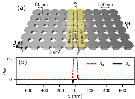
The device geometry used in this study is shown in Fig. 1(a). It is an ADL with a square lattice of antidots in a 5 nm thick Py film, with an antidot diameter of 80 nm and a lattice constant of nm. A three-antidot defect L3 (i.e., the area of 3 unit cells without the holes) is introduced in this structure. The system is uniformly magnetized by an in-plane bias magnetic field T directed along the -axis ( is the permeability of the vacuum). The SWs are excited by a microwave frequency magnetic field () generated by a CPW transducer consisting of a signal line of width separated by nm gaps from two identical ground lines (much wider than ), and with centered at . To enhance the excitation of SWs, the CPW is aligned along the -axis.
Two simulation methods are used to study the SW dynamics. Comsol Multiphysics package is used to calculate the magnonic band structure and cavity modes. Here, we use the finite element method (FEM) to solve the eigenproblem obtained from the linearized Landau-Lifshitz equation in real space and the frequency domain. The nonlinear effects are simulated in the real space and time domain (with finite difference time domain method, FDTD) using the Mumax3 micromagnetic solverVansteenkiste et al. (2014), which solves the full Landau-Lifshitz-Gilbert equation. The methods are described in detail in the Methods section. We use typical material parameters and typical values for Py, i.e., the saturation magnetization kA/m, the exchange constant pJ/m, and in FDTD simulations the damping . The magnetization dynamics inside the cavity are studied by probing the magnetization over nm area, i.e., three unit cells along the -axis and 1 along the -axis.
II Results
II.1 Band structure and the resonance spectra
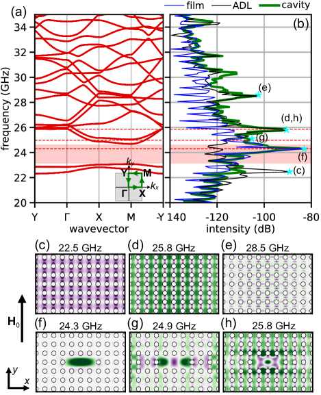
The first step in our investigation is examining the magnonic band structure of the ADL (without the defect). It is shown in Fig. 2(a) and is obtained by FEM at 0.5 T external magnetic field. The dispersion relation is over the path Y--X-M-Y in the first Brillouin zone (see the inset showing the first Brillouin zone and the high-symmetry path). Importantly, we see a well-defined full bandgap, ranging from 23.05 GHz to 24.95 GHz. The two bands below the band gap originate in the edge modes, i.e., the modes with the amplitude concentrated near the antidot edges, while the bands above are bulk modes, with the first one a fundamental mode of the ADL Tacchi et al. (2015).
The resonance response of the ADL, ADL with the L3 cavity, and as a reference of the plain Py film are shown in Fig. 2(b). The results are obtained with FDTD method by applying a spatially uniform broadband microwave magnetic field linearly polarized along the -axis:
| (1) |
where, the amplitude of microwave field: mT, the cut-off frequency: GHz, and . The intensity is calculated by integrating the normalized component of the magnetization vector () over the cavity region (i.e., the area of three unit cells in ADL and in the plane film) in a steady state. For presenting intensity, we use a logarithmic scale: in dB units.
For a plain Py film, we have only one distinctive peak at 24.3 GHz, corresponding to its FMR frequency. In the ADL there are several intense peaks Tacchi et al. (2015), the most intense are shown in Fig. 2(c-d): (c) the symmetric edge mode at 22.5 GHz ( band), (d) the fundamental excitation of the ADL at 25.8 GHz, and (e) a higher order SW at 28.5 GHz. This is in full agreement with the dispersion relation presented in Fig. 2(a). For the ADL with the cavity, we obtained the spectrum (green line in Fig.2(b)) which is quite similar to the undetected ADL, but with a well-defined peak at GHz, i.e. in the bandgap of the ADL. The peak represents the fundamental cavity mode (see Fig. 2(f)) which oscillates in phase, and its amplitude is confined inside the cavity. Interestingly, the frequency of this mode is the same as the FMR of a uniform Py film (see green and blue lines in Fig. 2(b)). There are also high-frequency resonant modes in the cavity with enhanced SW amplitude inside the cavity, as shown in Fig. 2(g) and (h). However, their frequencies overlap with the continuous bands of the ADL, and for that reason, the SW amplitude of these modes spread over the entire ADL.
Learned from photonics, the enhancement of the pumping power on the cavity mode shall result in entering into nonlinear regime whenever the cavity is a medium possessing some kind of nonlinearity Soljačić and Joannopoulos (2004); Lalanne, Sauvan, and Hugonin (2008). In magnetism, nonlinearity is its inherent property Gurevich and Melkov (1996). Therefore, in the following part of the manuscript, we will focus on the fundamental cavity mode pumped by the microwave magnetic field generated by CPW at 24.3 GHz and at high amplitudes.
II.2 Nonlinear dynamics
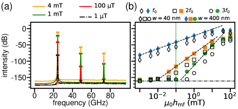
Frequency spectra of the ADL cavity system are shown in Fig. 3(a). The calculations were performed for 0.5 T magnetic field and the CPW of nm wide, located at the center of the cavity (), which generate the fields µT, 100 µT, 1 mT, and 4 mT. Three peaks, corresponding to the frequencies GHz, GHz, and GHz, are clearly visible at higher amplitudes of the microwave field, except the lowest considered value µT, where and are at the base signal level below dB. These frequencies correspond to the excitation of the fundamental cavity mode () and its second () and third () harmonics, respectively. The higher the amplitude of the microwave field, the higher the intensities of the modes. However, there are significant changes in the relative peak amplitudes between the fundamental cavity mode and its harmonics. For the fundamental cavity mode, there is an increase of 70 dB in the peak as we increase the microwave amplitude from 1 µT to 4 mT, whereas for the second and third harmonics, there is an increase of approximately 100 dB and 80 dB, respectively.
To shed more light on the efficiency of the SW excitations we perform systematic simulations with increased from 1 µT to 0.1 T using the same CPW antenna. The results are shown in Fig. 3(b) with full diamond, square, and circle dots for , , and , respectively. The intensity of the fundamental cavity mode increases from dB at mT till dB at 10 mT, and saturates with a further increase of . The intensities of the 2 and 3 harmonics start to grow at about 0.01 mT and 0.1 mT, respectively, grow almost linearly in this double logarithmic scale, and both reach an intensity only 20 dB less than the mode at 40 mT.
This means that the effectiveness of the nonlinear pumping of the second and third harmonic increases according to the square and cubic function of , with different threshold amplitudes of . This is according to the theoretical predictions for the plane film and plane waves Gurevich and Melkov (1996) indicating that the intensity of the harmonics:
| (2) |
Similar behaviour has already been observed experimentally in the microwave pumping of the elliptical Py nanodot (10 nm thick and 1 µm 0.5 µm lateral dimensions) saturated along the long axis Demidov et al. (2011). However, in Ref. [Demidov et al., 2011] the excitation was off-resonant, i.e., the generation of the 2 and 3 harmonic was only observed at and , with the pumping field frequency and , respectively. Here, and correspond to the frequency of the antisymmetric (with the nodal line along the long axis of the ellipse) and symmetric (fundamental) eigenmode of the nanodot, respectively. This means that for a given frequency of the microwave field or only the 2 or 3 harmonic can be observed.
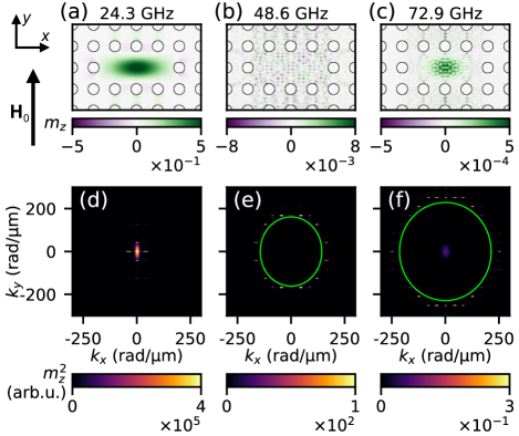
The spatial distributions of the fundamental cavity mode (), mode and at mT microwave excitation field are shown in Fig. 4(a), (b) and (c), respectively. The clear fine wavy pattern is seen at 48.6 and 72.9 GHz indicating a short wavelength of excited SWs. The amplitude of these harmonics spreads to the ADL, because, the accessible bands of the SWs in the ADL at these high frequencies are very dense with all the modes being propagating. There are slightly larger amplitudes along the -axis, which may be advantageous to use these modes to exploit the propagation of waves at these high frequencies. Indeed, Fig. 4(e)-(f) shows that in reciprocal space the 2 and 3 harmonics have discrete spectra at high values of wavenumber. There is a fine regularly spaced arrangement of the spots in Fig. 4(e)-(f) in the -space, which is related to the periodicity of the structure and the discrete values of the reciprocal lattice vectors. These bright spots are located around the almost circular isofrequency contours of SWs in the plain Py film at 48.6 and 72.9 GHz. Their radius is 180 and 220 rad/µm for and , and correspond to the SWs at wavelengths as short as 35 and 29 nm, respectively. The spots along the direction of have larger intensities that indicate the preferred direction of SW propagation, accordingly with observation in Fig. 4(b) and (c). In the future, the design of isofrequency contours of the ADL at relevant frequencies may allow the propagation direction of nonlinearly excited high-frequency SWs to be tailored to specific requirements. This can be achieved by proper design of the ADL geometry and the magnonic band structure Klos et al. (2015); Sadovnikov et al. (2016).
The spatial distributions of the fundamental cavity mode (), mode and at a microwave excitation field of mT are displayed in Fig. 4(a), (b) and (c). The figures present a neat, undulating pattern at 48.6 and 72.9 GHz indicating a short wavelength of excited SWs. Notably, the amplitude of these harmonics extends from the cavity to the ADL as the magnonic bands in the ADL at these high frequencies are very dense with all the modes being propagating. Slight amplitude increases occur along the -axis, suggesting that utilizing these modes could be useful for wave propagation at high frequencies. In fact, as seen in Fig. 4(e)-(f), the 2 and 3 harmonics possess discrete spectra in reciprocal space with regularly spaced spots at high wavenumbers. This pattern is related to the structure’s periodicity and the discrete values of its reciprocal lattice vectors. The bright spots are located around the almost circular isofrequency contours of SWs in the plain Py film at 48.6 and 72.9 GHz. For and , their radius is 180 and 220 rad/µm, respectively, which corresponds to the SWs at wavelengths as short as 35 and 29 nm. The spots have larger intensities along the direction of that indicate the preferred direction of SW propagation in the ADL, accordingly with observation in Fig. 4(b) and (c). In the future, designing isofrequency contours of the ADL at pertinent frequencies could enable tailoring of the propagation direction of nonlinearly excited high-frequency SWs towards specific needs. This objective can be accomplished through appropriate ADL geometry design and tailored magnonic band structure Klos et al. (2015); Sadovnikov et al. (2016).
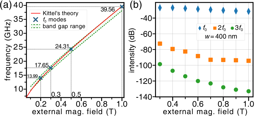
According to Eq. (2), the effectiveness of the nonlinear process can also be increased by decreasing . However, to maintain similar conditions for the ADL cavity system at different values of , the frequency of the fundamental cavity mode must follow the magnonic band gap as the magnetic field is varied. In Fig. 5(a), we show that the frequency of the fundamental cavity mode follows the FMR frequency of the plain Py film, and in a wide range of fields, i.e. from 0.2 to 1 T, the frequency of this mode (increasing from 13.99 to 39.56 GHz, respectively) falls into the magnonic band gap. Taking the frequencies of the FMR mode with increasing , assuming a pumped microwave magnetic field amplitude mT, we perform simulations. The results are shown in Fig. 5(b). We see that as the magnetic field decreases from 1 T to 0.3 T, the intensity of the 2 and 3 harmonics increases by 21.7 dB and 34.5 dB respectively. However, there is a downside to decreasing , it is that a lower frequency means longer wavelengths. In particular, at 1 T the 2 and 3 harmonics are at 79.12 and 118.68 GHz with wavelengths of 31.1 and 21.6 nm respectively, while at 0.2 T they are at 27.98 and 41.97 GHz and wavelengths of 61.4 and 39.8 nm, respectively.
II.3 Getting ready to experiment
The type of the ADL considered in this paper has been broadly investigated in the last few years Neusser et al. (2008, 2011); Tacchi et al. (2015); Zelent et al. (2017); Groß et al. (2022), so the nonlinear effects presented above should be feasible for experimental realization. To make our idea closer to realization we studied the influence of the CPW width and position with respect to the cavity center on the frequency multiplication.
The dependence of the SW intensity at on the position of the CPW ( nm emitting a microwave magnetic field mT) at T is shown in Fig. 6(a). Since is below the threshold for , the discussion below relates directly to and , but similar dependencies were also found at higher values of for . As expected, the intensities of the SWs decrease as the CPW signal line is moved away from the centre of the cavity. The rate of decrease accelerates significantly at nm. This is due to the fact that, from this position, the emission occurs outside the cavity, and the excitation of the cavity mode is only via evanescent SW modes in the ADL at the frequency of 24.3 GHz, which is in the bandgap. The study shows that the is the most appropriate for excitation of SWs inside the cavity for CPW narrower than the cavity length.
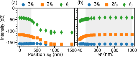
The influence of the width of the CPW signal line on the intensity of the excited SW modes is shown in Fig. 3(b). We place the CPW centrally over the cavity and increase starting at nm, we keep mT. The intensity of and mode increases with , and as expected saturates when the signal line covers the entire cavity. We conclude that the optimal conditions for multi-frequency SW mode generation are when the cavity is completely covered by the signal line, regardless of its position relative to the cavity centre. However, if the signal line is narrower than the cavity, the intensity of the excited SW modes becomes sensitive to and . Moreover, their values influence also the threshold field values for the generation of high-frequency harmonics. As shown in Fig. 3(b) the threshold fields are 0.04 and 0.4 mT for CPW with nm (empty symbols), which are higher than for nm, (solid symbols), 0.01 and 0.1 T, respectively.
III Summary
In this article, we describe a method to enhance the SW energy confined in a magnonic crystal cavity created in a thin Py-film based ADL to enter the nonlinear regime. We have shown that the microwave-pumped fundamental cavity mode, which has the frequency of the plain film FMR fitting into a complete bandgap, can easily reach the nonlinearity threshold leading to the generation of modes at multiple frequencies. Thus, we propose a way to generate high frequency SWs in the range of 28 to 79 GHz and 42 to 119 GHz with very short wavelengths of 62 to 31 nm and 40 to 22 nm for the 2 and 3 harmonics, respectively, by varying the external magnetic field from 1 to 0.3 T. The harmonics follow known dependencies on the amplitude of the pumped microwave field and the magnitude of the static magnetic fieldGurevich and Melkov (1996), allowing the effectiveness of multi-frequency mode generation to be significantly enhanced. The effects demonstrated in this paper can be achieved in standard ADLs using a simple CPW antenna, whose main limitation is the overlap of the signal line with the cavity surface. This provides an opportunity to investigate magnonics applications at high frequencies, which overlap with 6G microwave bands and have very short wavelengths, up to 100,000 times shorter than the wavelength of microwaves at these frequencies.
Further optimization of the magnonic crystal structure can even increase the demonstrated conversion efficiency of FMR oscillations to high-frequency oscillations. This can be achieved if, instead of using a cavity to confine only the SW at the input frequency (fundamental cavity mode), the structure also allows the mode to be confined at the output frequency(s) (high-frequency harmonics). Learning from photonics, not only can the power consumption be greatly reduced, but in principle 100% conversion can be achieved Bravo-Abad et al. (2007); Rodriguez et al. (2007).
Acknowledgements
This work was supported in part by the National Science Center Poland project OPUS-LAP no 2020/39/I/ST3/02413. The simulations were partially performed in Poznań Supercomputing and Networking Center and at the National Institute of Technology Calicut, India.
Methods
Micromagnetic simulations
To achieve precise outcomes for the ADL’s dispersion relations and to gain a better understanding of the complexity of the SW modes inside the crystal cavity, we utilized FEM and FDTD method to solve the Landau-Lifshitz and Maxwell equations. Within simulations, every magnetic moment in the predefined unit cells is given by normalized unit vectors where M is the total magnetization, and is the saturation magnetization of the ferromagnetic material. Our approach then focuses on solving the Landau-Lifshitz-Gilbert (LLG) equation:
| (3) |
where is the gyromagnetic ratio and is the dimensionless damping coefficient. The effective magnetic flux density field, includes externally applied field, , together with the magnetostatic demagnetization, , and the exchange field, :
| (4) |
Finite element method
In the FEM analysis implemented with Comsol Multiphysics, we addressed the eigenproblem derived from Eqs. 3 and 4, neglecting damping, i.e., , and defining the demagnetizing field amplitude, (), as the gradient of the magnetic scalar potential, : , which inside a magnetic body fulfill the equation: . By considering full magnetization saturation along the direction and utilizing a linear approximation, we could separate the magnetization vector into its static and dynamic (dependent on time and position r) components as , neglecting all nonlinear terms in the dynamic magnetization . Additional information on this methodology can be found in Refs. [Mruczkiewicz et al., 2013; Rychły et al., 2018].
Using Bloch-Floquet boundary conditions (BC) on the unit cell boundaries:
| (5) |
we model an infinite MC layer. Here, k is the 2D Bloch wavenumber, m is the normalized magnetic moment defined both at the target (dst) and source (src), r are the spatial coordinates of the boundaries where the BCs are applied, and is the imaginary unit. By parametrically sweeping the wavenumber, eigenfrequencies are determined at each interval. The resulting wavenumber versus frequency plots yields the dispersion curves for the periodic structure Hakoda et al. (2018); Collet et al. (2011).
For planes perpendicular to the plane of the MC layer, we have used Dirichlet BCs to suppress the scalar magnetic potential () at its out-of-plane boundaries. To ensure the physical accuracy and convergence of the simulation, it is crucial to position the conditions sufficiently far from the specimen. In our simulations, we set the cell’s height to be 10 times the layer’s unit cell width (1.5 µm). The average quality of the tetrahedral discretization mesh, as determined by the volume-to-length parameter, is 0.91. This results in a mesh comprising 13630 prisms for the MCs unit cell, with one element per thickness and excluding the surrounding environment. The cavity mode simulations in Comsol Multiphysics (Fig. 5) used the unit supercell approach, which consists of a cavity surrounded by 6 (parallel to the long side) and 8 (perpendicular) antidotes. This results in a symmetrical size of the supercell with a side equal to 1.35 µm. In this case, the height of the environment is 20 times this width (27 µm), and the amount of mesh elements of this supercell is 37330 with an average quality of 0.82 (and with one prism per thickness).
Finite difference time domain method
The time domain simulations in the paper have been obtained with the open-source software MuMax3 employing the finite difference time domain method Vansteenkiste et al. (2014) with the RK45 solver (based on Dormand-Prince method) Dormand and Prince (1980) to solve Eq. (3). The micromagnetic cell size was taken as nm3 with cell dimensions smaller than the exchange length . We used the in-plane periodic boundary condition (PBC), i.e., the supercell of dimension 4.5 µm 3 µm has been multiplied 10 and 50 times along the and directions, respectively.
To get the mode profiles, we calculate each magnetization component’s pointwise FFT over time and then visualize the real part corresponding to a particular resonance frequency, see details in Ref. [Gruszecki and Kisielewski, 2023].
The nonlinear response of the system excited by a single frequency microwave source was analyzed accordingly with the methodology used in Ref. [Gruszecki et al., 2022].
The mf current transmitted along the axis generates a magnetic field , which exerts a torque on the magnetization in Py. The dependence of with peak amplitude on coordinate can be approximated by the equationGruszecki et al. (2016):
| (6) |
DATA AVAILABILITY
The data that support the findings of this study are available from the corresponding author upon reasonable request.
References
- Kruglyak, Demokritov, and Grundler (2010) V. Kruglyak, S. Demokritov, and D. Grundler, “Magnonics,” Journal of Physics D: Applied Physics 43, 264001 (2010).
- Mahmoud et al. (2020) A. Mahmoud, F. Ciubotaru, F. Vanderveken, A. V. Chumak, S. Hamdioui, C. Adelmann, and S. Cotofana, “Introduction to spin wave computing,” Journal of Applied Physics 128, 161101 (2020).
- Nikitov et al. (2015) S. A. Nikitov, D. V. Kalyabin, I. V. Lisenkov, A. N. Slavin, Y. N. Barabanenkov, S. A. Osokin, A. V. Sadovnikov, E. N. Beginin, M. A. Morozova, Y. P. Sharaevsky, Y. A. Filimonov, Y. V. Khivintsev, S. L. Vysotsky, V. K. Sakharov, and E. S. Pavlov, “Magnonics: a new research area in spintronics and spin wave electronics,” Physics-Uspekhi 58, 1002 (2015).
- Chumak and Schultheiss (2017) A. V. Chumak and H. Schultheiss, “Magnonics: spin waves connecting charges, spins and photons,” Journal of Physics D: Applied Physics 50, 300201 (2017).
- Barman et al. (2021) A. Barman, G. Gubbiotti, S. Ladak, A. O. Adeyeye, M. Krawczyk, J. Grafe, C. Adelmann, S. Cotofana, A. Naeemi, V. I. Vasyuchka, B. Hillebrands, S. A. Nikitov, H. Yu, D. Grundler, A. V. Sadovnikov, A. A. Grachev, S. E. Sheshukova, J.-Y. Duquesne, M. Marangolo, G. Csaba, W. Porod, V. E. Demidov, S. Urazhdin, S. O. Demokritov, E. Albisetti, D. Petti, R. Bertacco, H. Schultheiss, V. V. Kruglyak, V. D. Poimanov, S. Sahoo, J. Sinha, H. Yang, M. Munzenberg, T. Moriyama, S. Mizukami, P. Landeros, R. A. Gallardo, G. Carlotti, J.-V. Kim, R. L. Stamps, R. E. Camley, B. Rana, Y. Otani, W. Yu, T. Yu, G. E. W. Bauer, C. Back, G. S. Uhrig, O. V. Dobrovolskiy, B. Budinska, H. Qin, S. van Dijken, A. V. Chumak, A. Khitun, D. E. Nikonov, I. A. Young, B. W. Zingsem, and M. Winklhofer, “The 2021 magnonics roadmap,” Journal of Physics: Condensed Matter 33, 413001 (2021).
- Flebus et al. (2023) B. Flebus, S. M. Rezende, D. Grundler, and A. Barman, “Recent advances in magnonics,” Journal of Applied Physics 133, 160401 (2023).
- Csaba, Papp, and Porod (2017) G. Csaba, A. Papp, and W. Porod, “Perspectives of using spin waves for computing and signal processing,” Physics Letters A 381, 1471–1476 (2017).
- Dieny et al. (2020) B. Dieny, I. L. Prejbeanu, K. Garello, P. Gambardella, P. Freitas, R. Lehndorff, W. Raberg, U. Ebels, S. O. Demokritov, J. Akerman, et al., “Opportunities and challenges for spintronics in the microelectronics industry,” Nature Electronics 3, 446–459 (2020).
- Hirohata et al. (2020) A. Hirohata, K. Yamada, Y. Nakatani, I.-L. Prejbeanu, B. Dieny, P. Pirro, and B. Hillebrands, “Review on spintronics: Principles and device applications,” Journal of Magnetism and Magnetic Materials 509, 166711 (2020).
- Pirro et al. (2021) P. Pirro, V. I. Vasyuchka, A. A. Serga, and B. Hillebrands, “Advances in coherent magnonics,” Nature Reviews Materials 6, 1114–1135 (2021).
- Chumak et al. (2022) A. V. Chumak, P. Kabos, M. Wu, C. Abert, C. Adelmann, A. Adeyeye, J. Åkerman, F. G. Aliev, A. Anane, A. Awad, et al., “Advances in magnetics roadmap on spin-wave computing,” IEEE Transactions on Magnetics 58, 1–72 (2022).
- Joannopoulos et al. (2008) J. Joannopoulos, S. G. Johnson, J. N. Winn, and R. D. Meade, Photonic Crystals: Molding the Flow of Light (Princeton University Press, 2008).
- Soljačić and Joannopoulos (2004) M. Soljačić and J. D. Joannopoulos, “Enhancement of nonlinear effects using photonic crystals,” Nature Materials 3, 211–219 (2004).
- Maldovan (2013) M. Maldovan, “Sound and heat revolutions in phononics,” Nature 503, 209–217 (2013).
- Vasileiadis et al. (2021) T. Vasileiadis, J. Varghese, V. Babacic, J. Gomis-Bresco, D. N. Urrios, and B. Graczykowski, “Progress and perspectives on phononic crystals,” Journal of Applied Physics 129, 160901 (2021).
- Krawczyk and Puszkarski (2008) M. Krawczyk and H. Puszkarski, “Plane-wave theory of three-dimensional magnonic crystals,” Physical Review B 77, 054437 (2008).
- Lenk et al. (2011) B. Lenk, H. Ulrichs, F. Garbs, and M. Munzenberg, “The building blocks of magnonics,” Physics Reports 507, 107–136 (2011).
- Krawczyk and Grundler (2014) M. Krawczyk and D. Grundler, “Review and prospects of magnonic crystals and devices with reprogrammable band structure,” Journal of Physics: Condensed Matter 26, 123202 (2014).
- Chumak, Serga, and Hillebrands (2017) A. Chumak, A. Serga, and B. Hillebrands, “Magnonic crystals for data processing,” Journal of Physics D: Applied Physics 50, 244001 (2017).
- Sokolovskyy and Krawczyk (2011) M. Sokolovskyy and M. Krawczyk, “The magnetostatic modes in planar one-dimensional magnonic crystals with nanoscale sizes,” Journal of Nanoparticle Research 13, 6085–6091 (2011).
- Mamica, Krawczyk, and Grundler (2019) S. Mamica, M. Krawczyk, and D. Grundler, “Nonuniform spin-wave softening in two-dimensional magnonic crystals as a tool for opening omnidirectional magnonic band gaps,” Physical Review Applied 11, 054011 (2019).
- Kłos et al. (2012) J. W. Kłos, M. Sokolovskyy, S. Mamica, and M. Krawczyk, “The impact of the lattice symmetry and the inclusion shape on the spectrum of 2D magnonic crystals,” Journal of Applied Physics 111, 123910 (2012).
- Kłos et al. (2014) J. W. Kłos, D. Kumar, M. Krawczyk, and A. Barman, “Influence of structural changes in a periodic antidot waveguide on the spin-wave spectra,” Physical Review B 89, 014406 (2014).
- Gubbiotti et al. (2010) G. Gubbiotti, S. Tacchi, M. Madami, G. Carlotti, A. Adeyeye, and M. Kostylev, “Brillouin light scattering studies of planar metallic magnonic crystals,” Journal of Physics D: Applied Physics 43, 264003 (2010).
- Vysotskii, Nikitov, and Filimonov (2005) S. Vysotskii, S. Nikitov, and Y. A. Filimonov, “Magnetostatic spin waves in two-dimensional periodic structures (magnetophoton crystals),” Journal of Experimental and Theoretical Physics 101, 547–553 (2005).
- Yu et al. (2007) M. Yu, L. Malkinski, L. Spinu, W. Zhou, and S. Whittenburg, “Size dependence of static and dynamic magnetic properties in nanoscale square permalloy antidot arrays,” Journal of Applied Physics 101, 09F501 (2007).
- Pechan et al. (2005) M. J. Pechan, C. Yu, R. Compton, J. Park, and P. Crowell, “Direct measurement of spatially localized ferromagnetic-resonance modes in an antidot lattice,” Journal of Applied Physics 97, 10J90 (2005).
- McPhail et al. (2005) S. McPhail, C. Gürtler, J. Shilton, N. Curson, and J. Bland, “Coupling of spin-wave modes in extended ferromagnetic thin film antidot arrays,” Physical Review B 72, 094414 (2005).
- Kostylev et al. (2008) M. Kostylev, G. Gubbiotti, G. Carlotti, G. Socino, S. Tacchi, C. Wang, N. Singh, A. O. Adeyeye, and R. L. Stamps, “Propagating volume and localized spin wave modes on a lattice of circular magnetic antidots,” Journal of Applied Physics 103, 07C507 (2008).
- Ulrichs, Lenk, and Münzenberg (2010) H. Ulrichs, B. Lenk, and M. Münzenberg, “Magnonic spin-wave modes in cofeb antidot lattices,” Applied Physics Letters 97, 092506 (2010).
- Hu et al. (2011) C.-L. Hu, R. Magaraggia, H.-Y. Yuan, C. Chang, M. Kostylev, D. Tripathy, A. Adeyeye, and R. Stamps, “Field tunable localization of spin waves in antidot arrays,” Applied Physics Letters 98 (2011).
- Tacchi et al. (2015) S. Tacchi, P. Gruszecki, M. Madami, G. Carlotti, J. W. Kłos, M. Krawczyk, A. Adeyeye, and G. Gubbiotti, “Universal dependence of the spin wave band structure on the geometrical characteristics of two-dimensional magnonic crystals,” Scientific Reports 5, 10367 (2015).
- Neusser et al. (2011) S. Neusser, G. Duerr, S. Tacchi, M. Madami, M. Sokolovskyy, G. Gubbiotti, M. Krawczyk, and D. Grundler, “Magnonic minibands in antidot lattices with large spin-wave propagation velocities,” Physical Review B 84, 094454 (2011).
- Gieniusz et al. (2017) R. Gieniusz, P. Gruszecki, M. Krawczyk, U. Guzowska, A. Stognij, and A. Maziewski, “The switching of strong spin wave beams in patterned garnet films,” Scientific Reports 7, 8771 (2017).
- Gołębiewski et al. (2020) M. Gołębiewski, P. Gruszecki, M. Krawczyk, and A. E. Serebryannikov, “Spin-wave Talbot effect in a thin ferromagnetic film,” Physical Review B 102, 134402 (2020).
- Riedel et al. (2023) C. Riedel, T. Taniguchi, L. Korber, A. Kakay, and C. H. Back, “Hybridization-induced spin-wave transmission stop band within a 1D diffraction grating,” Advanced Physics Research 2, 2200104 (2023).
- Ciubotaru et al. (2016) F. Ciubotaru, T. Devolder, M. Manfrini, C. Adelmann, and I. P. Radu, “All electrical propagating spin wave spectroscopy with broadband wavevector capability,” Applied Physics Letters 109, 012403 (2016).
- Woo, Delaney, and Beach (2017) S. Woo, T. Delaney, and G. S. D. Beach, “Magnetic domain wall depinning assisted by spin wave bursts,” Nature Physics 13, 448–454 (2017).
- Dieterle et al. (2019) G. Dieterle, J. Förster, H. Stoll, A. S. Semisalova, S. Finizio, A. Gangwar, M. Weigand, M. Noske, M. Fähnle, I. Bykova, J. Gräfe, D. A. Bozhko, H. Y. Musiienko-Shmarova, V. Tiberkevich, A. N. Slavin, C. H. Back, J. Raabe, G. Schütz, and S. Wintz, “Coherent excitation of heterosymmetric spin waves with ultrashort wavelengths,” Phys. Rev. Lett. 122, 117202 (2019).
- Yu et al. (2016) H. Yu, O. Allivy Kelly, V. Cros, R. Bernard, P. Bortolotti, A. Anane, F. Brandl, F. Heimbach, and D. Grundler, “Approaching soft X-ray wavelengths in nanomagnet-based microwave technology,” Nature Communications 7, 11255 (2016).
- Mushenok et al. (2017) F. B. Mushenok, R. Dost, C. S. Davies, D. A. Allwood, B. J. Inkson, G. Hrkac, and V. V. Kruglyak, “Broadband conversion of microwaves into propagating spin waves in patterned magnetic structures,” Applied Physics Letters 111, 042404 (2017).
- Kruglyak et al. (2006) V. V. Kruglyak, M. L. Sokolovskii, V. S. Tkachenko, and A. N. Kuchko, “Spin-wave spectrum of a magnonic crystal with an isolated defect,” Journal of Applied Physics 99, 08C906 (2006).
- Klos and Tkachenko (2013) J. W. Klos and V. S. Tkachenko, “Symmetry-related criteria for the occurrence of defect states in magnonic superlattices,” Journal of Applied Physics 113, 133907 (2013).
- Di et al. (2014) K. Di, V. L. Zhang, M. H. Kuok, H. S. Lim, S. C. Ng, K. Narayanapillai, and H. Yang, “Band structure of magnonic crystals with defects: Brillouin spectroscopy and micromagnetic simulations,” Phys. Rev. B 90, 060405 (2014).
- Morozova et al. (2015) M. A. Morozova, S. V. Grishin, A. V. Sadovnikov, D. V. Romanenko, Y. P. Sharaevskii, and S. A. Nikitov, “Band gap control in a line-defect magnonic crystal waveguide,” Applied Physics Letters 107, 242402 (2015).
- Kumar and Prabhakar (2018) N. Kumar and A. Prabhakar, “Resonant spin wave excitations in a magnonic crystal cavity,” Journal of Magnetism and Magnetic Materials 450, 46–50 (2018).
- Kumar (2022) N. Kumar, “Enhanced spin wave coupling between array of spin torque nano oscillators in magnonic crystal cavities,” Physica B: Condensed Matter 645, 414248 (2022).
- Lalanne, Sauvan, and Hugonin (2008) P. Lalanne, C. Sauvan, and J. Hugonin, “Photon confinement in photonic crystal nanocavities,” Laser & Photonics Reviews 2, 514–526 (2008).
- Schultheiss et al. (2019) K. Schultheiss, R. Verba, F. Wehrmann, K. Wagner, L. Körber, T. Hula, T. Hache, A. Kákay, A. A. Awad, V. Tiberkevich, A. N. Slavin, J. Fassbender, and H. Schultheiss, “Excitation of whispering gallery magnons in a magnetic vortex,” Phys. Rev. Lett. 122, 097202 (2019).
- Koerner et al. (2022) C. Koerner, R. Dreyer, M. Wagener, N. Liebing, H. G. Bauer, and G. Woltersdorf, “Frequency multiplication by collective nanoscale spin-wave dynamics,” Science 375, 1165–1169 (2022).
- Hula et al. (2022) T. Hula, K. Schultheiss, F. J. T. Goncalves, L. Körber, M. Bejarano, M. Copus, L. Flacke, L. Liensberger, A. Buzdakov, A. Kákay, M. Weiler, R. Camley, J. Fassbender, and H. Schultheiss, “Spin-wave frequency combs,” Applied Physics Letters 121, 112404 (2022).
- Groß et al. (2022) F. Groß, M. Weigand, A. Gangwar, M. Werner, G. Schütz, E. J. Goering, C. H. Back, and J. Gräfe, “Imaging magnonic frequency multiplication in nanostructured antidot lattices,” Phys. Rev. B 106, 014426 (2022).
- Vansteenkiste et al. (2014) A. Vansteenkiste, J. Leliaert, M. Dvornik, M. Helsen, F. Garcia-Sanchez, and B. Van Waeyenberge, “The design and verification of mumax3,” AIP advances 4, 107133 (2014).
- Gurevich and Melkov (1996) A. G. Gurevich and G. A. Melkov, Magnetization Oscillations and Waves (CRC Press, 1996).
- Demidov et al. (2011) V. E. Demidov, H. Ulrichs, S. Urazhdin, S. O. Demokritov, V. Bessonov, R. Gieniusz, and A. Maziewski, “Resonant frequency multiplication in microscopic magnetic dots,” Applied Physics Letters 99, 012505 (2011).
- Kalinikos and Slavin (1986) B. Kalinikos and A. Slavin, “Theory of dipole-exchange spin wave spectrum for ferromagnetic films with mixed exchange boundary conditions,” Journal of Physics C: Solid State Physics 19, 7013 (1986).
- Klos et al. (2015) J. W. Klos, P. Gruszecki, A. E. Serebryannikov, and M. Krawczyk, “All-angle collimation for spin waves,” IEEE Magnetics Letters 6, 1–4 (2015).
- Sadovnikov et al. (2016) A. V. Sadovnikov, E. N. Beginin, S. A. Odincov, S. E. Sheshukova, Y. P. Sharaevskii, A. I. Stognij, and S. A. Nikitov, “Frequency selective tunable spin wave channeling in the magnonic network,” Applied Physics Letters 108, 172411 (2016).
- Kittel (1946) C. Kittel, “Theory of the structure of ferromagnetic domains in films and small particles,” Physical Review 70, 965 (1946).
- Neusser et al. (2008) S. Neusser, B. Botters, M. Becherer, D. Schmitt-Landsiedel, and D. Grundler, “Spin-wave localization between nearest and next-nearest neighboring holes in an antidot lattice,” Applied Physics Letters 93 (2008).
- Zelent et al. (2017) M. Zelent, N. Tahir, R. Gieniusz, J. W. KÅ‚os, T. Wojciechowski, U. Guzowska, A. Maziewski, J. Ding, A. O. Adeyeye, and M. Krawczyk, 50, 185003 (2017).
- Bravo-Abad et al. (2007) J. Bravo-Abad, A. Rodriguez, P. Bermel, S. G. Johnson, J. D. Joannopoulos, and M. Soljačić, “Enhanced nonlinear optics in photonic-crystal microcavities,” Opt. Express 15, 16161–16176 (2007).
- Rodriguez et al. (2007) A. Rodriguez, M. Soljačić, J. D. Joannopoulos, and S. G. Johnson, “(2) and (3) harmonic generation at a critical power in inhomogeneous doubly resonant cavities,” Opt. Express 15, 7303–7318 (2007).
- Mruczkiewicz et al. (2013) M. Mruczkiewicz, M. Krawczyk, V. K. Sakharov, Y. V. Khivintsev, Y. A. Filimonov, and S. A. Nikitov, “Standing spin waves in magnonic crystals,” Journal of Applied Physics 113, 093908 (2013).
- Rychły et al. (2018) J. Rychły, V. S. Tkachenko, J. W. Kłos, A. Kuchko, and M. Krawczyk, “Spin wave modes in a cylindrical nanowire in crossover dipolar-exchange regime,” Journal of Physics D: Applied Physics 52, 075003 (2018).
- Hakoda et al. (2018) C. Hakoda, J. Rose, P. Shokouhi, and C. Lissenden, “Using Floquet periodicity to easily calculate dispersion curves and wave structures of homogeneous waveguides,” AIP Conference Proceedings 1949, 020016 (2018).
- Collet et al. (2011) M. Collet, M. Ouisse, M. Ruzzene, and M. Ichchou, “Floquet–Bloch decomposition for the computation of dispersion of two-dimensional periodic, damped mechanical systems,” International Journal of Solids and Structures 48, 2837–2848 (2011).
- Dormand and Prince (1980) J. R. Dormand and P. J. Prince, “A family of embedded runge-kutta formulae,” Journal of computational and applied mathematics 6, 19–26 (1980).
- Gruszecki and Kisielewski (2023) P. Gruszecki and J. Kisielewski, “Influence of dzyaloshinskii–moriya interaction and perpendicular anisotropy on spin waves propagation in stripe domain patterns and spin spirals,” Scientific Reports 13, 1218 (2023).
- Gruszecki et al. (2022) P. Gruszecki, K. Y. Guslienko, I. L. Lyubchanskii, and M. Krawczyk, “Inelastic spin-wave beam scattering by edge-localized spin waves in a ferromagnetic thin film,” Physical Review Applied 17, 044038 (2022).
- Gruszecki et al. (2016) P. Gruszecki, M. Kasprzak, A. E. Serebryannikov, M. Krawczyk, and W. Śmigaj, “Microwave excitation of spin wave beams in thin ferromagnetic films,” Scientific Reports 6, 22367 (2016).