A High-Frequency Flexible Ultrasonic Cuff Implant for High-Precision Vagus Nerve Ultrasound Neuromodulation ††thanks: This work was supported in part by the ECSEL Joint Undertaking project Moore4Medical, grant number H2020-ECSEL-2019IA-876190.
Abstract
In the emerging research field of bioelectronic medicine, it has been indicated that neuromodulation of the Vagus Nerve (VN) has the potential to treat various conditions such as epilepsy, depression, and autoimmune diseases. In order to reduce side effects, as well as to increase the effectiveness of the delivered therapy, sub-fascicle stimulation specificity is required. In the electrical domain, increasing spatial selectivity can only be achieved using invasive and potentially damaging approaches like compressive forces or nerve penetration. To avoid these invasive methods, while obtaining a high spatial selectivity, a 2 mm diameter extraneural cuff-shaped proof-of-concept design with integrated Lead Zirconate Titanate (PZT) based ultrasound (US) transducers is proposed in this paper. For the development of the proposed concept, wafer-level microfabrication techniques are employed. Moreover, acoustic measurements are performed on the device, in order to characterize the ultrasonic beam profiles of the integrated PZT-based US transducers. A focal spot size of around 200 by 200 is measured for the proposed cuff. Moreover, the curvature of the device leads to constructive interference of the US waves originating from multiple PZT-based US transducers, which in turn leads to an increase of 45% in focal pressure compared to the focal pressure of a single PZT-based US transducer. Integrating PZT-based US transducers in an extraneural cuff-shaped design has the potential to achieve high-precision US neuromodulation of the Vagus Nerve without requiring intraneural implantation.
Keywords cuff implant flex-to-rigid microfabrication piezoelectric ultrasound transducers PZT integration ultrasound neuromodulation Vagus Nerve
∗This work was supported in part by the ECSEL Joint Undertaking project Moore4Medical, grant number H2020-ECSEL-2019IA-876190.
1 Introduction
The application of ultrasound (US) technologies in the medical field has been extended from diagnostic imaging to therapeutic neuromodulation [1, 2, 3]. Among several stimulation targets, Vagus Nerve Stimulation (VNS) by means of focused US has been explored in recent years [4, 5, 6, 7]. The Vagus Nerve (VN) is a cranial nerve, part of the parasympathetic nervous system, consisting of afferent and efferent neurons [8, 9, 10, 11]. The VN nerve fascicles comprise of different nerve fibers, classified, according to Erlanger Gasser as type A, B, and C, each having their own functions, sizes (ranging from 0.5 up to 10 ), and conduction velocities (ranging from 0.5 to 120 m/s) [8, 9]. The VN is involved in the autonomic, cardiovascular, respiratory, gastrointestinal, immune, and endocrine systems [8]. Research shows that stimulation is useful in the therapy of epilepsy, depression, and several chronic diseases like Alzheimer’s disease, anxiety, congestive heart failure, pain, tinnitus, and inflammatory diseases [8, 11, 12, 13, 14, 15, 16]. Targeted stimulation on the sub-fascicle level is needed since unintended stimulation of other fascicles can lead to severe side effects [16, 17].
Conventionally, electricity is used to interact with the peripheral nervous system [18].
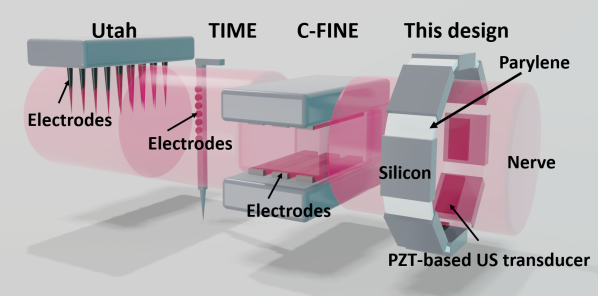
Transcutaneous VNS (tVNS) has been proposed as a non-invasive method [16, 19, 20, 21, 22, 23]. Although studies show that activation is elicited, the envisioned sub-fascicle stimulation resolution is not met [24]. Improved resolution can be achieved with implantable devices having embedded electrodes. A promising type of electrode for stimulation is the cuff electrode [25, 26, 27, 28, 29]. To reach the sub-fascicle resolution with electrodes, techniques like composite flat interface nerve electrodes (C-FINE) [30], slowly penetrating inter-fascicular nerve electrodes (SPINE) [31] and intra-fascicular techniques like longitudinal intra-fascicular electrode (LIFE) [25] and transverse intra-fascicular multichannel electrode (TIME) [25] and microelectrode arrays (MEAs), for example, the Utah array [32], are being developed [33]. The disadvantages of the aforementioned techniques are the needed compressive force and high invasiveness which increase the risk of damage to the nerve during implantation (Fig. 1). Therefore, this makes these techniques unsuitable for chronic applications.
Instead of using electrodes, integrating Lead Zirconate Titanate (PZT) based US transducers in a cuff implant form factor would enable the possibility of delivering US neuromodulation, extraneurally, yet with a high spatial resolution (Fig. 1). It has been previously demonstrated that a focal spot of 110 by 570 can be achieved when capacitive micromachined ultrasound transducers (CMUTs) are placed under the nerve and are geometrically curved at radii matching that of the VN [7]. Based on the well-described physical phenomena of US, it has been shown that US can be beam steered [34, 35] and can propagate through tissue for several centimeters without causing damage and side effects [2, 3, 36, 37]. Despite the biological mechanisms of US neuromodulation not yet being perfectly understood, it is likely that different combinations of partially overlapping mechanisms occur in the cell membrane depending on the US pulse regime [2, 3, 4, 38, 39, 40, 41]. Several studies show that focused US can elicit a physiological response in nerves [4, 5, 6, 28, 41, 42, 43, 44].
US waves are generated by either bulk piezoelectric transducers, or by flexural mode transducers, such as CMUTs and piezoelectric micromachined ultrasound transducers (PMUTs) [34, 45, 46, 47, 48]. For bulk mode PZT-based US transducers, which are characterized by a high transmit electroacoustic sensitivity (, where is the peak output pressure [kPa] and the driving voltage [V]) and a high-quality factor [34], PZT ceramics are commonly used due to their superior piezoelectric constants [49]. These are important characteristics for US neuromodulation as they lead to higher and more stable pressure amplitudes per driving voltage [34, 45, 46]. PMUT and CMUT devices have a lower and lower quality factor, and hence are more suitable for high-quality imaging and sensing applications where bandwidth is important [34, 49]. The pressure output of an integrated CMUT-array in a cuff implant form factor using 25 for excitation with beam steering has been measured to generate 1.7 MPa at most ( = 68 kPa/V) [35]. Another planar design with a 2D PZT-based US transducer array with 5 generated up to 0.1 MPa ( = 20 kPa/V) [34]. As the output pressure correlates with the driving voltage [50] and the focusing of the beam, the is a good parameter for comparison.
Currently, there is no consensus on the amount of intensity or pressure needed for neuromodulation of peripheral nerves. However, research suggests that peripheral nerves require higher pressures than e.g. brain tissue for neuromodulation and that pressures in the range of 3 MPa are sufficient[4]. To date, a method to integrate bulk PZT-based US transducers in a flexible cuff compatible with VNS was not yet demonstrated [24].
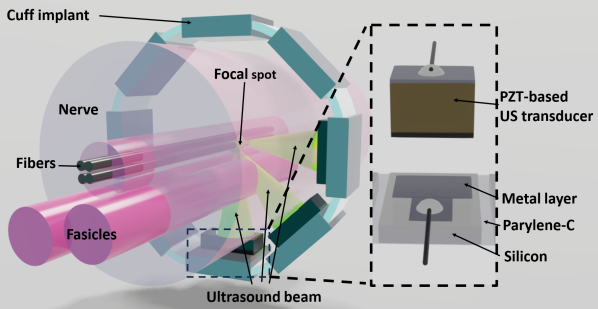
In this paper, a form factor compatible with the VN with integrated PZT-based US transducers is proposed (Fig. 2). We investigate whether this design can reach high acoustic pressures with low peak-to-peak driving voltages and still maintain high spatial resolution. The organization of the paper is as follows: in section 2 the design choices and the necessary COMSOL Multiphysics [51] simulations are elaborated upon. Section 3 describes the design and elaborates on the wafer-level microfabrication process flow and the assembly of the PZT-based cuff prototypes (section 3.1). In section 4 the device is characterized and the acoustic measurements are described. The results are discussed in section 5, whereas section 6 draws the conclusions.
2 Simulations
| Parameters | Numbers |
| Frequency | 8.4 |
| Diameter | 2 |
| # of PZT-based US transducers | 3 |
| PZT thickness | 254 |
| PZT aperture | 1100 |
| PZT length | 450 |
| Focal length | 1 |
| Active area | 1.49 |
The concept, shown in Fig. 1, is a cuff-shaped, island-bridge structure with three 8.4 MHz PZT-based US transducers. In Table 1 the main design parameters are given. The inner diameter of the cuff is 2 mm, as the VN has a diameter of about 2-4 mm [7]. The aperture of the PZT relates to the focal length and driving frequency according to [52]:
| (1) |
where is the focal length [m], the aperture [m], the driving frequency [Hz] and the speed of sound in the medium [m/s]. The focal length of each PZT-based US transducer has been designed to be around 1 mm, such that the focal point of all PZT-based US transducers comprising the cuff is in the center of the design, as well as, of the nerve.
As the cuff form factor is defined with a radius of 1 mm, the aperture of single PZTs can also not be larger than the chord of 12.5 % of the circumference, otherwise, it will limit the circular shape.
Frequencies for neuromodulation in pre-clinical or clinical research can scale from sub-MHz (transcranial US neuromodulation) to a few MHz (VNS). Increasing the frequency leads to a tradeoff between spatial resolution and absorption, hence the frequency should be carefully set. The driving frequency is inversely proportional to the aperture (1), the focal spot size (2) and (3), and the thickness (4) of the PZT [45, 52]. The equations for the full width at half bandwidth FHWM [34], the depth of field DOF [34], and thickness of the PZT at resonance () [49] are given in (2), (3), and (4) respectively.
| (2) |
where is the wavelength of the US waves [m], is the focal depth [m] and the aperture [m].
| (3) |
| (4) |
In this study, it has been assumed that the acoustic wave is propagating in a homogeneous medium and that there is no gap between the implant and the nerve. The PZT thickness, defining the resonance frequency, can constrain the curvature of the design as the top of the PZTs could touch each other for large PZT thicknesses. As the thickness of the PZTs is in the range of the silicon thickness (around 300 ), it does not constrain the design. Moreover, the frequency determines the aperture, whereas the aperture has a tradeoff between the focal length and the maximum size for curvature. Therefore, the frequency should be set to be as high as possible to have a high spatial resolution, yet with the PZT-based US transducer size fitting the design dimensions. Therefore, a frequency of 8.4 MHz has been set. Moreover, other research shows that similar driving frequencies (9.56 and 8.4 MHz) provide resolution in the -range [34, 52].
2.1 Methods
To define the effect of the number of PZT-based US transducers and to verify the design, COMSOL Multiphysics simulations have been performed. The 2D finite element method simulations have been conducted in the frequency domain, using the pressure acoustics, solid mechanics, and electrostatics COMSOL models. A free triangular mesh with a maximum element size of has been used. Water medium has been used as a replacement for nerve tissue since the acoustic properties are similar [45]. The boundary of the water medium is set to be perfectly matched to avoid reflections at the edges. In addition, PZT-5H has been used as a piezoelectric material for the PZT-based US transducers and a driving voltage of 10 has been defined, being the maximum output voltage of the function generator used during measurements (Section 4). To ensure the focal point is in the center of the device, the distance between the surface of a PZT-based US transducer and the center has been set to 1 mm.
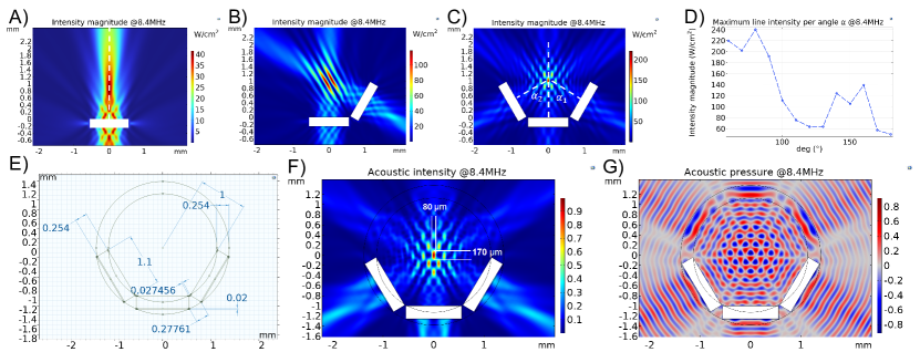
The first simulation has been done to investigate the effect of the number of PZT-based US transducers on the acoustic profile and pressure levels. The number of PZT-based US transducers has been swept from an individual PZT-based US transducer to three PZT-based US transducers. The next simulation is a rotational sweep of the angles , which are the angles between one of the side PZT-based US transducers and the bottom-middle PZT-based US transducer (Fig. 3C). These angles are equal for the left and right side () and are being swept from 50∘ to 180∘.
Later, a full design with three PZT-based US transducers and a polymer ring of parylene-C was simulated to verify the focal spot and the design dimensions. The cuff implant form factor has been modeled as a perfect circle. The simulation dimensions are shown in Fig. 3E.
2.2 Results
From simulations, it was found that the increase in the number of PZT-based US transducers increases the acoustic intensity magnitude in case they are placed in a curved configuration. According to the simulations, the focal intensity is 40 for one PZT-based US transducer and increases to 120 for two PZT-based US transducers and to 210 for three PZT-based US transducers (Fig. 3A, Fig. 3B, and Fig. 3C) respectively. The increase of the acoustic intensity becomes less significant the more PZT-based US transducers are added. Moreover, with more PZT-based US transducers the focal spot size decreases and destructive interference patterns appear.
The result of a sweep of three PZT-based US transducers is shown in Fig. 3D. It can be observed that for smaller angles between the PZT-based US transducers, a higher acoustic intensity magnitude exists in this form factor. The intensity for an angle of 180∘, so the PZT-based US transducers oppose each other, is reduced to 75% of the maximum acoustic intensity magnitude. Although opposite-placed PZT-based US transducers might be beneficial in different designs and in cases of beam steering, in this design, it has been concluded based on this simulation that opposite-placed PZT-based US transducers should be avoided. This limits the placement of PZT-based US transducers to only 40% of the cuff circumference.
Moreover, the number of PZT-based US transducers is determined by the aperture of the PZTs and the inter-PZT distance. The aperture of the PZTs is set by the aforementioned driving frequency. The inter-PZT distance between the PZT-based US transducers when curved, is optimized to be a multiple of for minimizing the side lobes while having the smallest distance (Fig. 3D). For a driving frequency of 8.4 MHz, three PZT-based US transducers do fit in the 2 mm cuff design (Fig. 3E).
The acoustic intensity magnitude and pressure profiles for the cuff implant design can be found in Fig. 3F and 3G, respectively. The acoustic waves are emitted from both the front- and back-side of the PZT-based US transducer. Note that in COMSOL the intensity is a vector whereas the pressure is a scalar, resulting in different profiles. It can be observed that the focal spot for the acoustic intensity has a size of 80 by 170 and it is located in the center of the cuff shape.
3 Design
The development of the proposed cuff is based on wafer-level microfabrication processes [34, 53, 54, 55]. The flexibility of the final device is provided by the island-bridge approach where silicon islands are etched and interconnected with each other via a parylene-C layer.
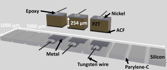
The metal layer provides the electrical connection to the PZT-based US transducers (Fig. 4). The contact pads (500 by 500 ) are directly connected to this metal layer with 500 -width traces.
The single planar device is 7 mm by 1 mm (Fig. 4). According to the simulations in section 2, the resonance frequency and thus, the driving frequency of the cuff concept is 8.4 MHz resulting in a PZT thickness of around 254 . Taking the design constraints into account, only three PZT-based US transducers can be placed (Fig. 4). The sizes of the PZT-based US transducers can be found in table 1.
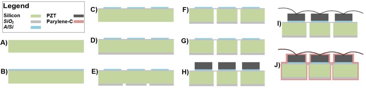
3.1 Wafer-level microfabrication
The processing steps for the proposed wafer-level microfabrication process can be found in Fig. 5. A 300 -thick double-sided polished 100 mm diameter p-type silicon wafer has been used as a starting material (Fig. 5A). On top of the wafer 1 of Plasma-Enhanced Chemical Vapor Deposition (PECVD) oxide is deposited at 400∘C for insulation and as a landing layer for deep reactive ion etching (DRIE) from the backside of the wafer, required later in the process. On top of this layer, a metal interconnect layer of 1 -thick AlSi (99%/1%) is sputtered at 50∘C (Fig. 5B). AlSi (99%/1%) has been used due to its high conductivity, low cost, and availability. This metal layer is patterned using a 2.1 -thick positive photoresist (SPR3012, Shipley) as a soft mask and is etched using HBr/Cl2-based dry etching processes (Fig. 5C).
Next, a 4 -thick PECVD layer at 400∘ is deposited at the backside as a hard mask (Fig. 5D). The PECVD oxide layer at the backside is opened using a fully dry etch step (Fig. 5E). For this etch step a 3.1 -thick positive photoresist (SPR3012, Shipley) as soft mask has been used. Afterward, the bulk silicon of the wafer is etched till the layer at the top side using DRIE (Fig. 5F). This creates a 1 -thick membrane in between rigid, silicon islands. This membrane serves as support during the parylene-C coating later on in the process.
Next, the wafer is diced in a 2-phase dicing process (Fig. 5G) using the dicer (DAD3221, Disco). In the first phase, the wafer is attached with the top side to an ultraviolet-sensitive dicing foil and the wafer is diced into several larger pieces of around 3 by 3 . After releasing, each piece is individually diced into separate devices. For this phase, an acetone-sensitive dicing foil is used, since the devices can be self-released from the foil using acetone, thus preserving the thin membrane. To maintain the thin membrane during dicing, the dicing speed is set to 1 mm/s and a thin silicon edge (10 ) is preserved, which does not interfere during the bending process.
Commercial PZT-5H 8 MHz sheets from piezo.com are used for the PZT-based US transducers. For conduction purposes, a 30 -thick anisotropic conductive film (ACF, ARclad 9032-70) is attached to one side of the PZT-5H sheet before dicing. The other side of the PZT has a 0.1 sputtered nickel layer (Fig. 4). The PZT-sheet with ACF is diced into the sizes presented in Table 1. With the pick-and-place tool (T-300 bonder, Accelonix), the PZTs are placed on the metal contact rings at the silicon substrate (Fig. 5H). Despite the beamsplitter being used for alignment, some spatial variation exists.
The top connection between the PZT-based US transducers is made with 50 -thick tungsten wire which is connected using a layer of silver conductive paste (42469, Thermofischer). After curing, a layer of conductive epoxy (EPOTEK-H20E, Epoxy technology) is applied. This gives a mechanically robust and electrically conductive connection. To avoid, mechanical interference of the wires during the curvature of the device, each PZT and contact pad is individually connected with a tungsten wire (Fig. 5I). Afterward, the wires of the three contact pads are bundled, likewise the wires of the three PZT-based US transducers. In this way, two connections, one for the ground and one for the signal, are available during the measurements. After the attachment of the tungsten wire, the device is encapsulated (Fig. 5J) using a 5 -thick parylene-C coating (PDS 2010, Specialty coating systems). Parylene-C is known due to its conformal coating properties and high chemical inertness [56]. In addition, it is mechanically flexible and therefore used as the flexible interconnect between the silicon islands in the island-bridge design (Fig. 4).
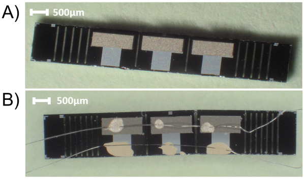
A micrograph of a single device after step H (Fig. 5H) is shown in Fig. 6A. Fig. 6B shows a micrograph of a device with attached wires.
4 Characterization
The characterization has been done to show the impact of curvature on the focal spot.
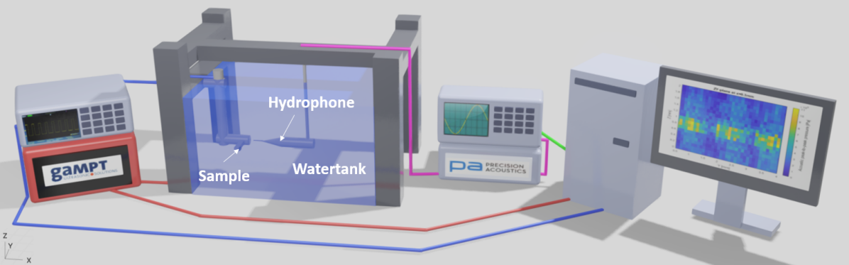
For the measurements, a device has been measured in a planar and curved configuration. The measurements are done in a water tank in which the device is fixed in a 3D-printed holder. The measurement setup is shown in Fig. 7. A function generator (DG4202, RIGOL) drives the device, generating a 10 , 30 pulses, 8.3 MHz, 1 ms period burst.
The US pressure is measured using a fibre-optic hydrophone (FSV2-5580-10, Precision Acoustics) which is put into position with a 3D-axis motorized stage (SFS630, GAMPT soundfield scanning drive). The fibre-optic hydrophone is connected to the fibre-optic hydrophone system (FOHSv2, Precision Acoustics) and the signal is read out with an oscilloscope (DSO-X 3032A, Agilent Technologies). The oscilloscope, function generator and 3D-axis motorized stage can be controlled using a Matlab-GUI on a computer. The hydrophone has a sensitivity of 268 mV/MPa at a frequency of 8 MHz. Linear interpolation gives a sensitivity of 281 mV/MPa for 8.4 MHz. The 3D-printed holder for the measurements in the planar configuration can be seen in Fig. 9A. A small custom-made PCB board is attached to connect the device to the oscilloscope connectors.
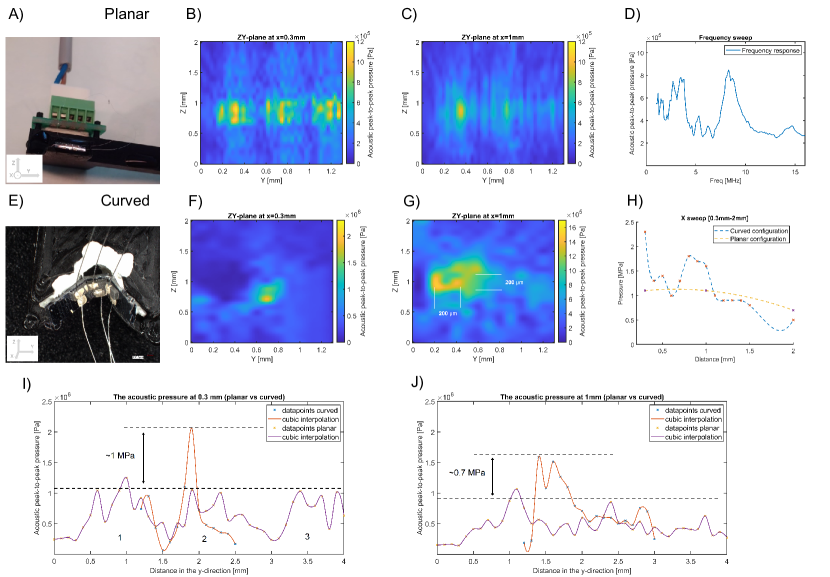
Before the acoustic measurements, a frequency sweep (from 1 to 16 MHz) was applied to the PZT-based US transducers to obtain the resonance frequency of the device (Fig. 9D). For this measurement, a resonance frequency of 8.3 MHz was obtained which is used as the driving frequency for the function generator. The acoustic profiles are measured in a zy-plane parallel to the front of the device for different distances in the x-direction. The data is post-processed using a cubic interpolation method with 100 in between points at both axes. The scans for the 0.3 mm (near-field) and 1 mm (focal spot) distance can be found in Fig. 9B and Fig. 9C respectively. Each PZT-based US transducer has its own acoustic profile and some profile distortion is visible. The acoustic peak pressure varies among the PZT-based US transducers from 1.1 MPa to 700 kPa (Fig. 9C) gaining 900 kPa on average. The focal spot of a single PZT-based US transducer has a size of around 100 by 200 . The reaches 110 kPa/V.
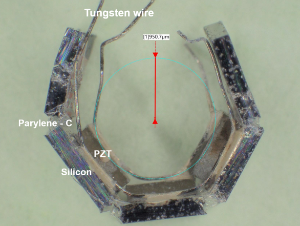
A fully curved device can be observed in Fig. 8 with an inner radius of 0.95 mm. A topview of the setup of the curved sample in the water tank is given in Fig. 9E. The 3D-printed holder contains a half-circle which, together with the device, has an inner diameter of 2 mm. The device is pushed inside the half-circle into a thin layer of glue pad that holds the device in a half-curved position. The acoustic profiles are scanned in the same way as for the planar configuration. The scans for 0.3 mm and 1 mm in the x-direction are shown in Fig. 9F and Fig. 9G respectively. The focal spot size is around 200 by 200 and is slightly larger than the simulations (Fig. 9G).
The focal pressure magnitude in the curved configuration is increased by 0.7 MPa compared to the average focal pressure magnitude of the single PZT-based US transducer in the planar configuration (Fig. 9I and Fig. 9J). Having a peak focal pressure of 1.6 MPa results in a of 160 kPa/V. The pressure profiles of Fig. 9I and Fig. 9J are obtained from the cross sections of Figures 9B and 9C at Z=0.9 mm, from Figure 9F at Z=0.7 mm, and from Figure 9G at Z=1 mm. For the planar pressure profile line in Figure 9I, the locations of the PZT-based US transducers in the graph are indicated with the numbers 1, 2, and 3. In Figure 9H, the maximum focal pressures for each measurement in the curved and planar configuration are combined in a distance plot. The crosses indicate the maximum values, whereas the dashed line is an interpolation.
5 Discussion
The simulations show that the focal region of the cuff implant design has grating lobes resulting in high-intensity and high-pressure areas around the focal spot (Figure 3F). This can potentially modulate unwanted regions in the VN. Beam steering could be implemented to reduce these grating lobes and target the nerve more specifically [35].
Comparing the results with the simulations, it can be observed that the resonance frequency is well preserved after the fabrication of the device. The simulated resonance frequency is 8.4 MHz whereas the measured resonance frequency is 8.3 MHz. The distortion and harmonics at lower frequencies could be explained by the loading of the PZT-based US transducers due to the attachment of the tungsten wire changing the frequency behavior. Another reason might be the partial detachment of the PZT from the substrate as research shows that that can induce harmonics [57]. The detachment of the PZT from the substrate might be a consequence of poor adhesion to the ACF, placement variations of the PZTs, mechanical vibrations during operation or corrosion of the metal tracks due to water inlet via microcracks in the parylene-C encapsulation.
Moreover, the measurement in the curved configuration shows that a local maximum exists in the near-field that has a higher pressure magnitude than the focal spot (Figure 9F). This could potentially result in unwanted VN areas being modulated. These near-field maxima are highly dependent on the medium and thus difficult to model [52]. They could for instance be reduced by implementing beam-steering [34] or improving the curvature of the device during the measurements.
To reduce the variations and distortions, some assembly steps could be fine-tuned. The process parameters of the pick-and-place of the PZTs can be refined and it can be automated, as this is a standard packaging step. This will result in more precise PZT placement. Moreover, it could be transformed into a top and backside dicing approach at which the dicing determines the alignment of the PZTs [34]. The manual attachment of the tungsten wire could be replaced by adding an evaporated or sputtered top metal plane on top of the PZT-based US transducers which will hypothetically reduce the distortion in the US profile.
Another reason for the difference between the pressure profile in the simulations and the measured profile is the simplifications and idealities in the simulation model. In the simulation, only the PZT and a perfectly cylindrical parylene-C ring are taken into account. In reality, fabrication non-idealities, island-bridge instead of pure parylene-C, manual variations during PZT placement, and the attachment of the tungsten wire, degrade the performance of the PZT-based US transducer, leading to a different pressure profile. Moreover, the distortion of the focal spot might result from the non-perfect curvature and PZT placement variations. Due to small misalignments and tilting of the sample in the water tank during measurements in the planar configuration, there is a difference between the measured acoustic pressures among the PZT-based US transducers.
The island-bridge structure with silicon islands and parylene-C interconnects gives flexibility and the ability of the device to have a curvature of 2 mm in diameter (Fig. 8). However, as parylene-C is naturally brittle, it is still a vulnerability and the device should be handled with care. The robustness could be improved by increasing the layer thickness or creating a multilayer on top which protects the underlying parylene-C layer. However, this might affect the acoustic performance as the attenuation could increase, depending on the layer thickness, material properties, and the driving frequency. A biocompatible, transparent and cuff-implant-suitable alternative is Polydimethylsiloxane (PDMS) [58]. Research shows that this material can be used in combination with parylene-C as an encapsulation layer [59, 60].
For the metal layer, AlSi (99%/1%) is used. However, during measurements, device failure occurs. This is likely due to the non-optimized adhesion between the parylene-C and the metal tracks and the high water vapor transmission rate (WVTR) of parylene-C [61]. Post-treatment of the metal layer or replacing it by another more inert metal could improve the robustness of the metal layer[62]. Moreover, a multilayer encapsulation might increase the robustness [63] as well. Another advantage is that a multilayer encapsulation could be used for acoustic matching. A matching layer increases the acoustic power transfer between two non-matching media (PZT and water) and will increase the acoustic output pressure. Besides a backing layer, a matching layer could be included in the wafer-level microfabrication process as well [45]. The multi-layer polymer-metal structure for acoustic matching might be promising as parylene-C can still be used as an encapsulation layer [64, 65, 66].
To increase the acoustic output pressure even more, PZT-5H piezoelectric material could be replaced by the PMN-PT piezoelectric material as it has better electromechanical properties [67]. Moreover, beam steering could be implemented by dicing each individual PZT-based US transducer into a 2D-phased array [34]. This opens the potential to target the VN at various locations within the radius of the cuff implant. Another benefit of beam steering is the ability to compensate for mechanical deformation.
The measurements show that the fabricated device in curved configuration has a high , indicating that per applied driving voltage to the device the output pressure increases with that amount (5).
| (5) |
For a driving voltage of 10 V used in this study, the output pressure is using the of 160 kPa/V. For comparison, CMUTs designed for VN neuromodulation have a of 68 kPa/V [35]. In addition, a body-conformal active ultrasound patch presented by Pashaei et al shows a of 80 kPa/V [24]. This means that for similar driving voltages, significantly higher output pressures are obtained with this proposed design.
6 Conclusion
This paper proposes a 1 mm by 7 mm wafer-level microfabricated, island-bridge cuff implant with an inner diameter of 2 mm. COMSOL Multiphysics simulations have been performed to investigate the effect of the number of PZT-based US transducers and to verify the design. The wafer-level microfabrication and assembly consist of standardized and scalable process steps.
The device is driven at 8.3 MHz and has a focal length of 1 mm. Three commercial PZT-5H US transducers are integrated generating 0.9 MPa on average at the focal spot for each individual PZT-based US transducer in a planar configuration ( = 110 kPa/V) whereas, 1.6 MPa is generated at the focal spot in curved configuration ( = 160 kPa/V). The focal spot of the curved cuff implant is around 200 by 200 .
The measurements show the potential of a cuff-shape design with a PZT-based US transducer array as the output focal pressure is increased by at least 45% (taking the peak pressures at the focal spot for both the planar (1.1 MPa) and curved (1.6 MPa) configuration) compared to the measured focal pressures of the single PZT-based US transducers in the planar configuration.
In conclusion, the integration of PZT-based US transducers in a cuff-shaped design opens a new path towards a technique for high-precision VNS.
Acknowledgment
The authors highly appreciated the support of the staff of the Else Kooi Lab at Delft University of Technology.
References
- [1] Oluigbo, C. & Rezai, A. Addressing Neurological Disorders With Neuromodulation. IEEE Transactions On Biomedical Engineering. 58, 1907-1917 (2011)
- [2] Blackmore, J., Shrivastava, S., Sallet, J., Butler, C. & Cleveland, R. Ultrasound Neuromodulation: A Review of Results, Mechanisms and Safety. Ultrasound In Medicine & Biology. 45, 1509-1536 (2019)
- [3] Kamimura, H., Conti, A., Toschi, N. & Konofagou, E. Ultrasound neuromodulation: mechanisms and the potential of multimodal stimulation for neuronal function assessment. Front Phys. 8 (2020), 2296-424x Journal Article 2020/06/09 Front Phys. 2020 May;8:150. doi: 10.3389/fphy.2020.00150. Epub 2020 May 26.
- [4] Downs, M., Lee, S., Yang, G., Kim, S., Wang, Q. & Konofagou, E. Non-invasive peripheral nerve stimulation via focused ultrasound less or greater in vivo less or greater. Physics In Medicine And Biology. 63, 035011 (2018,1), doi:10.1088/1361-6560/aa9fc2
- [5] Kim, M., Kamimura, H., Lee, S., Aurup, C., Kwon, N. & Konofagou, E. Image-guided focused ultrasound modulates electrically evoked motor neuronal activity in the mouse peripheral nervous system in vivo. Journal Of Neural Engineering. 17, 026026 (2020)
- [6] Cotero, V., Miwa, H., Graf, J., Ashe, J., Loghin, E., Di Carlo, D. & Puleo, C. Peripheral Focused Ultrasound Neuromodulation (pFUS). Journal Of Neuroscience Methods. 341 pp. 108721 (2020)
- [7] Kawasaki, S., Giagka, V., De Haas, M., Louwerse, M., Henneken, V., Van Heesch, C. & Dekker, R. Pressure measurement of geometrically curved ultrasound transducer array for spatially specific stimulation of the vagus nerve. 2019 9th International IEEE EMBS Conference On Neural Engineering (NER), 2019, doi: 10.1109/NER.2019.8717064
- [8] Yuan, H. & Silberstein, S. Vagus Nerve and Vagus Nerve Stimulation, a Comprehensive Review: Part I. Headache: The Journal Of Head And Face Pain. 56, 71-78 (2016)
- [9] Settell, M., Knudsen, B., Dingle, A., McConico, A., Nicolai, E., Trevathan, J., Ross, E., Pelot, N., Grill, W., Gustafson, K., Shoffstall, A., Williams, J., Zeng, W., Poore, S., Populin, L., Suminski, A. & Ludwig, K. Functional Vagotopy in the Cervical Vagus Nerve of the Domestic Pig: Implications for the Study of Vagus Nerve Stimulation. Cold Spring Harbor Laboratory, 2019
- [10] Jayaprakash, N., Song, W., Toth, V., Vardhan, A., Levy, T., Tomaio, J., Qanud, K., Mughrabi, I., Chang, Y., Rob, M., Daytz, A., Abbas, A., Nassrallah, Z., Volpe, B., Tracey, K., Al-Abed, Y., Datta-Chaudhuri, T., Miller, L., Barbe, M., Lee, S., Zanos, T. & Zanos, S. Organ- and function-specific anatomical organization of vagal fibers supports fascicular vagus nerve stimulation. Brain Stimulation. 16, 484-506 (2023)
- [11] Groves, D. & Brown, V. Vagal nerve stimulation: a review of its applications and potential mechanisms that mediate its clinical effects. Neuroscience & Biobehavioral Reviews. 29, 493-500 (2005)
- [12] Johnson, R. & Wilson, C. A review of vagus nerve stimulation as a therapeutic intervention. Journal Of Inflammation Research. Volume 11 pp. 203-213 (2018)
- [13] Panebianco & Marson, A. Vagus nerve stimulation for focal seizures. Cochrane Database Of Systematic Reviews. (2022), doi:10.1002/14651858.CD002896
- [14] Howland, R. Vagus Nerve Stimulation. Current Behavioral Neuroscience Reports. 1, 64-73 (2014)
- [15] Lee, S., Peh, W., Thakor, N., Yen, S. & Lee, C. Vagus nerve stimulation (VNS) for heart rate control using novel neural interfaces. (2017)
- [16] Yuan, H. & Silberstein, S. Vagus Nerve and Vagus Nerve Stimulation, a Comprehensive Review: Part II. Headache: The Journal Of Head And Face Pain. 56, 259-266 (2016)
- [17] Dirr, E., Patel, Y., Lester, L., Delgado, F. & Otto, K. Targeted Vagus Nerve Stimulation does not Disrupt Cardiac Function in the Diabetic Rat. (2019)
- [18] Giagka, V. & Serdijn, W. Realizing flexible bioelectronic medicines for accessing the peripheral nerves – technology considerations. Bioelectronic Medicine. 4 (2018), doi: 10.1186/s42234-018-0010-y
- [19] Yap, J., Keatch, C., Lambert, E., Woods, W., Stoddart, P. & Kameneva, T. Critical Review of Transcutaneous Vagus Nerve Stimulation: Challenges for Translation to Clinical Practice. Frontiers In Neuroscience. 14 (2020)
- [20] De Smet, S., Baeken, C., Seminck, N., Tilleman, J., Carrette, E., Vonck, K. & Vanderhasselt, M. Non-invasive vagal nerve stimulation enhances cognitive emotion regulation. Behaviour Research And Therapy. 145 pp. 103933 (2021)
- [21] Shin, K., Bae, Y., Park, H., Kang, D. & Kang, M. The Effect of Electrode Distance on the Voltage Distribution during Non-invasive Vagus Nerve Stimulation – a Preliminary Study. (2023)
- [22] Levitsky, A., Klein, J., Artemiadis, P. & Buneo, C. Effects of Transcutaneous Electric Nerve Stimulation on Upper Extremity Proprioceptive Function. (2020)
- [23] Gurel, N., Shandhi, M., Bremner, J., Vaccarino, V., Ladd, S., Shallenberger, L., Shah, A. & Inan, O. Toward closed-loop transcutaneous vagus nerve stimulation using peripheral cardiovascular physiological biomarkers: A proof-of-concept study. (2018)
- [24] Pashaei, V., Dehghanzadeh, P., Enwia, G., Bayat, M., Majerus, S. & Mandal, S. Flexible Body-Conformal Ultrasound Patches for Image-Guided Neuromodulation. IEEE Transactions On Biomedical Circuits And Systems. 14, 305-318 (2020)
- [25] Rijnbeek, E., Eleveld, N. & Olthuis, W. Update on Peripheral Nerve Electrodes for Closed-Loop Neuroprosthetics. Frontiers In Neuroscience. 12 (2018)
- [26] Rodriguez, F., Ceballos, D., Schuttler, M., Valero, A., Valderrama, E., Stieglitz, T. & Navarro, X. Polyimide cuff electrodes for peripheral nerve stimulation. Journal Of Neuroscience Methods. 98, 105-118 (2000)
- [27] Stieglitz, T., Beutel, H., Schuettler, M. & Meyer, J. Micromachined, Polyimide-Based Devices for Flexible Neural Interfaces. Biomedical Microdevices. 2, 283-294 (2000)
- [28] Forssell, M., Fedder, G., Sciullo, M., Mou, C., Sun, F., Simpson, T., Xiao, G., Fisher, L., Bettinger, C. & Horn, C. Compliant adhesive cuff electrode for selective stimulation in rat vagus nerve. (2019)
- [29] Haugland, M. A flexible method for fabrication of nerve cuff electrodes. 18th Annual International Conference Of IEEE Engineering-in-Medicine-amd-Biology-Society. 18 pp. 359-360 (1997)
- [30] Freeberg, M., Stone, M., Triolo, R. & Tyler, D. The design of and chronic tissue response to a composite nerve electrode with patterned stiffness. Journal Of Neural Engineering. 14, 036022 (2017), doi:10.1088/1741-2552/aa6632
- [31] Tyler, D. & Durand, D. A slowly penetrating interfascicular nerve electrode for selective activation of peripheral nerves. IEEE Transactions On Rehabilitation Engineering. 5, 51-61 (1997)
- [32] Kim, G., Kim, K., Lee, E., An, T., Choi, W., Lim, G. & Shin, J. Recent Progress on Microelectrodes in Neural Interfaces. Materials. 11, 1995 (2018), doi:10.3390/ma11101995
- [33] Yildiz, K., Shin, A. & Kaufman, K. Interfaces with the peripheral nervous system for the control of a neuroprosthetic limb: a review. Journal Of NeuroEngineering And Rehabilitation. 17 (2020)
- [34] Costa, T., Shi, C., Tien, K., Elloian, J., Cardoso, F. & Shepard, K. An Integrated 2D Ultrasound Phased Array Transmitter in CMOS With Pixel Pitch-Matched Beamforming. IEEE Transactions On Biomedical Circuits And Systems. 15, 731-742 (2021)
- [35] Kawasaki, S., Dijkema, E., Saccher, M., Giagka, V., Schleipen, J. & Dekker, R. Schlieren visualization of focused ultrasound beam steering for spatially specific stimulation of the vagus nerve. 2021 10th International IEEE EMBS Conference On Neural Engineering (NER), 2021, doi: 10.1109/NER49283.2021.9441225 (2021)
- [36] O’Brien, W. Ultrasound–biophysics mechanisms. Progress In Biophysics And Molecular Biology. 93, 212-255 (2007), Effects of ultrasound and infrasound relevant to human health
- [37] Kele, H. Ultrasonography of the peripheral nervous system. Perspectives In Medicine. 1 pp. 417-421 (2012,9)
- [38] Plaksin, M., Shoham, S. & Kimmel, E. Intramembrane Cavitation as a Predictive Bio-Piezoelectric Mechanism for Ultrasonic Brain Stimulation. Physical Review X. 4 (2014)
- [39] Heimburg, T. & Jackson, A. On soliton propagation in biomembranes and nerves. Proceedings Of The National Academy Of Sciences. 102, 9790-9795 (2005), doi:10.1073/pnas.0503823102
- [40] Oh, S., Lee, J., Kim, H., Lee, J., Han, S., Bae, J., Hong, G., Koh, W., Kwon, J., Hwang, E. & Al. Ultrasonic Neuromodulation via Astrocytic TRPA1. Current Biology. 29, 3386-3401.e8 (2019)
- [41] Colucci, V., Strichartz, G., Jolesz, F., Vykhodtseva, N. & Hynynen, K. Focused ultrasound effects on nerve action potential in vitro. Ultrasound In Medicine & Biology. 35, 1737-47 (2009)
- [42] Lee, S., Jung, J., Chae, Y., Kang, J. & Ieee Fabrication and Characteristics of the Implantable and Flexible Nerve Cuff Electrode for Neural Interfaces. 4th International IEEE/EMBS Conference On Neural Engineering. pp. 80-+ (2009)
- [43] Juan, E., González, R., Albors, G., Ward, M. & Irazoqui, P. Vagus nerve modulation using focused pulsed ultrasound: Potential applications and preliminary observations in a rat. International Journal Of Imaging Systems And Technology. 24, 67-71 (2014), doi:10.1002/ima.22080
- [44] Foley, J., Little, J. & Vaezy, S. Effects of high-intensity focused ultrasound on nerve conduction. Muscle & Nerve. 37, 241-50 (2008), Foley JL Little JW Vaezy S
- [45] Rathod, V. A Review of Acoustic Impedance Matching Techniques for Piezoelectric Sensors and Transducers. Sensors. 20, 4051 (2020)
- [46] Shen, K. & Maharbiz, M. Design of Ceramic Packages for Ultrasonically Coupled Implantable Medical Devices. IEEE Transactions On Biomedical Engineering. 67, 2230-2240 (2020)
- [47] Wang, Z., Xue, Q., Chen, Y., Shu, Y., Tian, H., Yang, Y., Xie, D., Luo, J. & Ren, T. A Flexible Ultrasound Transducer Array with Micro-Machined Bulk PZT. Sensors. 15, 2538-2547 (2015)
- [48] Yang, Y., Tian, H., Yan, B., Sun, H., Wu, C., Shu, Y., Wang, L. & Ren, T. A flexible piezoelectric micromachined ultrasound transducer. RSC Advances. 3, 24900 (2013)
- [49] Akasheh, F., Myers, T., Fraser, J., Bose, S. & Bandyopadhyay, A. Development of piezoelectric micromachined ultrasonic transducers. Sensors And Actuators A: Physical. 111 pp. 275-287 (2004,3)
- [50] Rivandi, H. & Costa, T. A 2D Ultrasound Phased-Array Transmitter ASIC for High-Frequency Ultrasound Stimulation and Powering. IEEE Transactions On Biomedical Circuits And Systems. pp. 1-12 (2023)
- [51] Comsol Acoustics Module User’s Guide. (https://doc.comsol.com/5.4/doc/ com.comsol.help.aco/AcousticsModu leUsersGuide.pdf)
- [52] Gougheri, H., Dangi, A., Kothapalli, S. & Kiani, M. A Comprehensive Study of Ultrasound Transducer Characteristics in Microscopic Ultrasound Neuromodulation. IEEE Transactions On Biomedical Circuits And Systems. 13, 835-847 (2019)
- [53] Shi, C., Costa, T., Elloian, J. & Shepard, K. Monolithic Integration of Micron-scale Piezoelectric Materials with CMOS for Biomedical Applications. 2018 IEEE International Electron Devices Meeting (IEDM). pp. 4.5.1-4.5.4 (2018)
- [54] Shi, C., Andino-Pavlovsky, V., Lee, S., Costa, T., Elloian, J., Konofagou, E. & Kenneth L. Shepard Application of a sub-0.1-mm3 implantable mote for in vivo real-time wireless temperature sensing. Science Advances. 7, eabf6312 (2021), doi:10.1126/sciadv.abf6312
- [55] Shi, C., Costa, T., Elloian, J., Zhang, Y. & Shepard, K. A 0.065-mm3 Monolithically-Integrated Ultrasonic Wireless Sensing Mote for Real-Time Physiological Temperature Monitoring. IEEE Transactions On Biomedical Circuits And Systems. 14, 412-424 (2020)
- [56] Ortigoza-Diaz, J., Scholten, K., Larson, C., Cobo, A., Hudson, T., Yoo, J., Baldwin, A., Weltman Hirschberg, A. & Meng, E. Techniques and Considerations in the Microfabrication of Parylene C Microelectromechanical Systems. Micromachines. 9, 422 (2018), doi:10.3390/mi9090422
- [57] Yelve, N., Mitra, M. & Mujumdar, P. Higher harmonics induced in lamb wave due to partial debonding of piezoelectric wafer transducers. NDT & E International. 63 pp. 21-27 (2014)
- [58] Miranda, I., Souza, A., Sousa, P., Ribeiro, J., Castanheira, E., Lima, R. & Minas, G. Properties and Applications of PDMS for Biomedical Engineering: A Review. Journal Of Functional Biomaterials. 13 pp. 2 (2021,12)
- [59] Babaroud, N., Dekker, R., Serdijn, W. & Giagka, V. PDMS-Parylene Adhesion Improvement via Ceramic Interlayers to Strengthen the Encapsulation of Active Neural Implants. 2020 42nd Annual International Conference Of The IEEE Engineering In Medicine & Biology Society (EMBC). pp. 3399-3402 (2020), doi: 10.1109/EMBC44109.2020.9175646
- [60] Bakhshaee, N., Dekker, R., Hölck, O., Tiringer, U., Taheri, P., Horváth, D., Nánási, T., Ulbert, I., Serdijn, W. & Giagka, V. Investigation of the long-term adhesion and barrier properties of a PDMS-Parylene stack with PECVD ceramic interlayers for the conformal encapsulation of neural implants. 2021 23rd IEEE European Microelectronics and Packaging Conference (EMPC), 2021, doi: 10.23919/EMPC53418.2021.9584961.
- [61] Nanbakhsh, K., Kluba, M., Pahl, B., Bourgeois, F., Dekker, R., Serdijn, W. & Giagka, V. Effect of Signals on the Encapsulation Performance of Parylene Coated Platinum Tracks for Active Medical Implants. 2019 41st Annual International Conference Of The IEEE Engineering In Medicine And Biology Society (EMBC). pp. 3840-3844 (2019), doi: 10.1109/EMBC.2019.8857702
- [62] Mahmood, M., Chioibasu, D., Ur Rehman, A., Mihai, S. & Popescu, A. Post-Processing Techniques to Enhance the Quality of Metallic Parts Produced by Additive Manufacturing. Metals. 12, 77 (2022)
- [63] Pak, A., Nanbakhsh, K., Hölck, O., Ritasalo, R., Sousa, M., van Gompel, M., Pahl, B., Wilson, J., Kallmayer, C., & Giagka, V. Thin Film Encapsulation for LCP-Based Flexible Bioelectronic Implants: Comparison of Different Coating Materials Using Test Methodologies for Life-Time Estimation. Micromachines. vol. 13, no. 4, pp. 544 (2022). doi: 10.3390/mi13040544.
- [64] Fei, C., Ma, J., Chiu, C., Williams, J., Fong, W., Chen, Z., Zhu, B., Xiong, R., Shi, J., Hsiai, T. & Al. Design of matching layers for high-frequency ultrasonic transducers. Applied Physics Letters. 107, 123505 (2015), doi:10.1063/1.4931703
- [65] Toda, M. & Thompson, M. Detailed investigations of polymer/metal multilayer matching layer and backing absorber structures for wideband ultrasonic transducers. IEEE Transactions On Ultrasonics, Ferroelectrics, And Frequency Control. 59, 231-242 (2012)
- [66] Yang, X., Fei, C., Xinhaosun, Hou, S. & Chen, J. Multi-layer polymer-metal structures for acoustic impedance matching in high-frequency broadband ultrasonic transducer design. (2019)
- [67] Kim, K., Hsu, D., Ahn, B., Kim, Y. & Barnard, D. Fabrication and comparison of PMN-PT single crystal, PZT and PZT-based 1-3 composite ultrasonic transducers for NDE applications. Ultrasonics. 50, 790-797 (2010)