Towards quantitative Low Energy Ion Scattering on CaSiO3 from Comparison to Multiple-Scattering-Resolved Dynamical Binary Collision Approximation Simulations
Abstract
We perform Low Energy Ion Scattering with 1 keV He ions on CaSiO3 using a commercial electrostatic detector system and determine the charge fraction of scattered ions from comparison with Binary Collision Approximation simulations. The simulations take dynamical surface changes due to surface cleaning Ar sputtering into account and scattered He particles are separated into single, dual, and multiple scattering trajectories. We find that the charge fraction of single and dual scattered He is about 10 times higher than the one for multiple collisions. Our results show that quantitative concentration profiles can be inferred from this method, if the charge fraction components are determined first.
I Introduction
Low Energy Ion Scattering (LEIS) is a powerful method with the ultimate surface sensitivity among all ion beam analysis methods [1]. Used for both structural analysis by channeling and blocking [2, 3, 4] as well as elemental composition analysis [5] it is, however, a common misconception that LEIS probes purely the very outermost surface layer [6]. Incoming ions can undergo single or multiple scattering events at the surface or in deeper layers both contributing to the final energy spectrum. One additional challenge arises from the fact that scattered ions may have changed their charge state. Some LEIS methods rely on the measurement of the time-of-flight of scattered ions and are therefore not sensitive to changing ion charges [7, 8], but more commonly, electrostatic LEIS (esaLEIS) is used. The latter has the advantage of possibly much higher solid angles especially in commercial devices like the ionTOF Qtac system [9], but suffers from the fact that only charged ions can be detected. With a high solid angle, spectra can potentially be acquired in a small amount of time even when detecting only charged scattered ions and consequently dynamic changes in a surface due to, for example, chemical reactions or material deposition can be monitored [10, 11].
However, in esaLEIS a quantification of the elemental composition is limited at best, because the charge fraction of scattered ions/atoms is typically unknown and cannot be modelled accurately with present theoretical models. As a result, mostly qualitative analysis of dynamical surface changes are done with esaLEIS [12].
Here we go one step further and show that with the correct simulation toolkit one can in fact extract the charge fraction of scattered He ions even from a multi-component target which also dynamically changes during surface preparation by Ar ion sputtering. The determined charge fraction only has a weak dependence on the dynamic surface changes during Ar sputtering and may therefore serve as a reference for similar samples allowing for full quantification [13].
In the following we use CaSiO3 as a target material, because it is an analog material for the regolith of the Moon’s and Mercury’s surfaces where backscattering of 1 keV/u protons from the Sun (solar wind) is used in orbital probe missions to observe the ion-surface interaction, which significantly alters planetary surfaces through sputtering, weathering and ion implantation [14, 15, 16, 17].
II Methods
We use both, a commercial LEIS setup and two binary collision approximation codes, to fit experimental spectra and extract the charge fraction in this procedure. Details are described below.
II.1 Experimental Setup
Samples of CaSiO3 were produced by a costum-built Pulsed Laser Deposition setup equipped with a KrF excimer laser (Coherent compex Pro) operating at 5 Hz. At the target 105 mJ per pulse arrived, which yields a fluence of J/cm2. The deposition was carried out at a substrate temperature of C in 0.04 mbar O2 and a target-substrate distance of 6 cm for 15 min. We used a natural mineral target [18] and the substrate is a standard Si(001) wafer piece of cm2.
The CaSiO3 layer on Si(001) substrate is loaded in an ionTOF Qtac LEIS system with a base pressure in the low mbar range. The sample is sputtered by Ar+ ions at 2 keV energy and incidence angle with respect to the surface normal. An area of m2 is irradiated by the Ar ions. After each fluence step of Ar/cm2, a LEIS spectrum is taken. In total we apply an Ar fluence of Ar/cm2. Therefore, we track dynamic surface changes during the surface preparation and cleaning procedure.
LEIS spectra are obtained with 1 keV He+ ions under normal incidence. An area of m2 in the middle of the Ar-sputtered area is probed by the He beam. Scattered He ions are detected by the annular Qtac detector under scattering angle. Note, that the detector is a toroidal electrostatic analyzer covering azimuthal angle, which can only measure charged particles. Ions which neutralize in the process of scattering are not detected. The energy analyzer is operated in constant pass energy mode at 3 keV and has an energy resolution of of the pass energy, i.e. 42 eV in our case.
II.2 Dynamical Sputtering BCA
We use SDTrimSP 6.09 to extract elemental depth profiles after each Ar sputter fluence we applied in the experiment [19]. Therefore, we use the dynamic mode of this binary collision approximation code [20]. For implanted Ar ions during the sputtering process we do not restrict the Ar retention in SDTrimSP (and reach up to at%). We checked the influence of a limited Ar retention of 0 and 5 at% as well (see Fig. 7 in the Appendix). Note, that subsequent diffusion or outgasing effects of near-surface implanted Ar is not taken into account by the simulation. Since Ar and Ca have basically the same mass, He scattering from Ca and implanted Ar cannot be distinguished in the experiment and we have therefore no direct experimental benchmark on how much Ar is actually implanted and with which depth distribution.
II.3 Multiple-Scattering-Resolved BCA
The elemental depth profiles after Ar sputtering are taken as an input for additional BCA simulations using the IMINTDYN code [21]. IMINTDYN is a derivative of SDTrimSP, i.e. using the same BCA description, but including some additional features, for example, to divide particle trajectories between single and multiple scattering. With this code we calculate the He scattering yield for a range of around the mean scattering angle of using standard ZBL potentials, and energy loss functions. Note, that the exact form of the screened interaction potential and the electronic energy loss model (incl. straggling) can potentially influence the LEIS spectra [22, 23, 24, 25]. We further divide the yield into three parts, i.e. into scattered particles which scatter once with an angle of (single scattering), into scattered particles which scatter once with an angle of and once with an angle of (dual scattering), and into scattered particles with all other possible trajectories (multiple scattering). Note, that scattering angles in a single scattering event are associated with very small energy transfers. We also want to point out that the maximum depth from which ions can still be back-scattered with multiple scattering amounts to nm in our simulations.
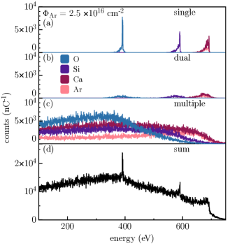
From the IMINTDYN code we do get the single, dual, and multiple scattering parts of the LEIS spectrum also for each target element (see Fig. 2). For dual and multiple scattering the scattered He is assigned to the element where it obtains the largest scattering angle. However, since we cannot resolve the LEIS signal from Ca and from implanted Ar, we will not use elemental-resolved simulated LEIS spectra for comparison with experiment, but rather the elemental-summed single, dual, and multiple scattering contributions.
III Results
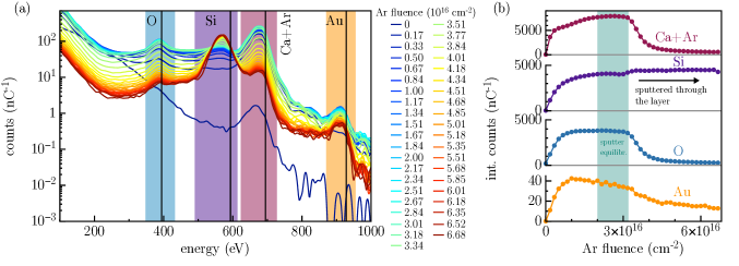
We obtain LEIS spectra after each Ar sputtering step, which can be seen in Fig. 1(a). Initially the sample is contaminated with light elements (zero Ar fluence, dark blue). After the initial Ar sputtering step the expected multiple scattering background for this sample can already be recovered in the experiment (blue to cyan, multiple scattering background visible by the signal height in between O and Si). At larger fluences (yellow to red), we see a reduced O and Ca signal and an increasing relative contribution of Si. Furthermore, we see a peak at about 900 eV, which would correspond to Au or Pt and can be attributed to contaminations of the layer during the PLD growth process.
In Fig. 1(b) the integral of the correspondingly colored regions in (a) are shown as function of Ar fluence. One can see, that the signal intensity increases initially due to surface cleaning. For Ar/cm2 a slow variation of the Ca and Si signal can be observed, which we attribute to dynamical surface composition changes due to Ar sputtering. For Ar/cm2 the signal for O, Si, and Ca remain constant, which we assign to the region of sputtering equilibrium, i.e. no more dynamical surface changes occur. For even larger fluences the Ca(+Ar) signal as well as the O signal decrease and the Si signal increases, which is understood by sputtering entirely through the PLD-deposited CaSiO3 layer on Si wafer substrate. The Au (or Pt) contamination decreases slowly for small fluences and somewhat faster when the layer is sputtered through. Here it should be noted that the heavy elements are sputtered at reduced rates and are preferentially intermixed in the layer (and the substrate) [26] which explains the signal even when the top layer is sputtered off.
The IMINTDYN simulation provides both elemental-resolved and multiple-scattering-resolved LEIS spectra after each Ar sputtering step. One example of these results after Ar/cm2 (in the sputter equilibrium) is shown in Fig. 2. One can see that single collisions lead to the commonly known sharp peaks in the energy spectrum (a), while dual (b) and multiple (c) scattering lead to increasingly broad spectral components. The sum of all components is shown in (d), which would be the LEIS spectrum one would expect if one did not resolve the He trajectories by element or number of scattering events.
IV Discussion
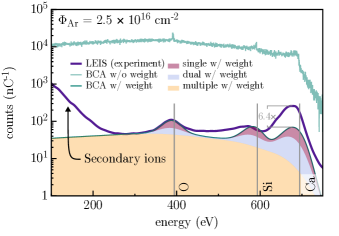
In order to compare the BCA simulated LEIS spectra with experiment, the experimental LEIS spectra are fit by
| (1) |
through variation of , and , which are the charge fractions for single, dual, and multiple collisions, respectively. The , and are the partial LEIS spectra from a BCA calculation (cf. Fig. 2(a)-(c)), which are additionally convoluted with a Gaussian kernel to account for the finite energy resolution of 42 eV in the experiment. An example of the fit result is shown in Fig. 3 (green solid line). Also the non-weighted sum (cf. Fig. 2(d)) is shown, which is about 2 orders of magnitude larger than the experimental spectrum. This already indicates that the average charge fraction is in the range of . Also the overall shape is not in agreement with the experiment and only by applying the fit procedure described above, the experimental spectrum can be reproduced. Note that the experimental spectrum shows an exponential increase below 200 eV, which is commonly attributed to the presence of charged secondary ions in the spectrum and could be filtered from the spectrum by using a time-of-flight analysis of the He ions through the electrostatic analyzer [27]. The overall agreement between the BCA fit and the experiment allows the extraction of the charge fractions for the individual scattering events (single, dual, and multiple). Note, that there is a discrepancy between fit and experiment for the Si signal and the Ca+Ar signal. The latter can be partially attributed to the fact, that the Ar implantation in the BCA elemental depth profiles does not include Ar out or in diffusion, which might appear in the experiment. The Si signal is systematically lower in the experiment than retrieved from the fit, which could be an indication for charge fraction differences when the He undergoes single and dual scattering on Si in contrast to Ca and O. However, due to the overlap of Ca and Ar, we do not further consider elemental-sensitive charge fractionization in this work.
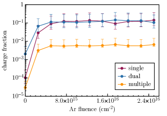
The fitting was done for every Ar fluence step and the extracted charge fractions are shown in Fig. 4. For the initial Ar fluences the fitting is not reliable, because surface contaminations are not considered in the LEIS BCA simulation and therefore the overall spectral shapes are widely different. However, for Ar fluences above Ar/cm2 the charge fractions for the individual scattering numbers can be well extracted. From Fig. 4 one can see that the charge fraction of multiple scattering is in the range of , while single and dual scattering trajectories have a much higher charge fraction of about . The charge fraction analysis is robust against the Ar sputtering and therefore the extracted fractions remain almost constant for the Ar fluence range from pre-equilibrium towards the sputter equilibrium. The corresponding change in surface composition can be extracted from the dynamic SDTrimSP simulations and is shown in Figs. 5 and 6 in the Appendix.
The large charge fraction for single and dual scattering in contrast to multiple collisions might result from different neutralization and re-ionization schemes active. Single and dual collision trajectories at the low He ion energy appear close to the surface, i.e. the overall interaction time of the ion with the material is limited at most to a few femtoseconds, so that a substantial fraction of of the incoming particles remain in a charged state. However, in these two cases relatively strong scattering (i.e. at small interatomic distances) occurs which leads to large deflection angles. Multiple scattering, on the other hand, is associated with a comparatively long trajectory inside the material, whereas each scattering event could be considered a soft scattering. The interplay and relative importance of impact parameter dependence and interaction time in ion neutralization was recently discussed intensively [28, 29] and remains still elusive in heavily asymmetric ion-target combinations like it is the case here.
V Conclusion
We show that LEIS spectra can be fit by BCA simulations to extract the charge fraction of the scattered He ions using esaLEIS with multi-component oxide target materials. The charge fraction depends on the details of the ion trajectory in the surface. Dual and multiple scattering can have large contributions to an observed spectrum indicating that larger depths contribute significantly. It is therefore important to properly setup the target surface system in a BCA simulation for LEIS and we do this by dynamically calculating the surface atomic concentration profiles after Ar ion sputtering from separate BCA simulations. Some effect of the chemical nature of the scattering partner on the He charge fraction can be inferred from our data as well, while further in-depth analysis on this effect is needed.
Since the determined charge fractions appear stable against further Ar sputtering of the surface, we suggest that this charge fraction can be used for similar target systems as a standard. Then, esaLEIS will allow full quantification of unknown samples, as long as the charge fraction between single, dual, and multiple scattering remains similar.
Acknowledgements.
The authors appreciate funding (WST3-F-542638/004-2021) by EFRE and the State of Lower Austria. Funding was further provided by the Austrian FWF (Y1174-N36, I4914-N, P36264-N).References
- Prusua et al. [2015] S. Prusua, P. Prochazka, P. Bábor, T. Sikola, R. Ter Veen, M. Fartmann, T. Grehl, P. Brüner, D. Roth, P. Bauer, and H. H. Brongersma, Highly Sensitive Detection of Surface and Intercalated Impurities in Graphene by LEIS, Langmuir 31, 9628 (2015).
- Primetzhofer et al. [2007] D. Primetzhofer, S. Markin, R. Kolarova, M. Draxler, R. Beikler, E. Taglauer, and P. Bauer, On the surface sensitivity of angular scans in LEIS, Nuclear Instruments and Methods in Physics Research Section B: Beam Interactions with Materials and Atoms 258, 36 (2007).
- Tromp et al. [1984] R. Tromp, H. Kersten, E. Granneman, F. Saris, R. Koudijs, and W. Kilsdonk, A new UHV system for channeling blocking analysis of solid surfaces and interfaces, Nuclear Instruments and Methods in Physics Research Section B: Beam Interactions with Materials and Atoms 4, 155 (1984).
- O’connor et al. [1986] D. O’connor, R. Macdonald, W. Eckstein, and P. Higginbottom, Surface structure analysis using low energy scattered and recoiling ions, Nuclear Instruments and Methods in Physics Research Section B: Beam Interactions with Materials and Atoms 13, 235 (1986).
- Brongersma et al. [2007] H. Brongersma, M. Draxler, M. Deridder, and P. Bauer, Surface composition analysis by low-energy ion scattering, Surface Science Reports 62, 63 (2007).
- Ter Veen et al. [2009] H. Ter Veen, T. Kim, I. Wachs, and H. Brongersma, Applications of High Sensitivity-Low Energy Ion Scattering (HS-LEIS) in heterogeneous catalysis, Catalysis Today 140, 197 (2009).
- Roth et al. [2013] D. Roth, D. Goebl, D. Primetzhofer, and P. Bauer, A procedure to determine electronic energy loss from relative measurements with TOF-LEIS, Nuclear Instruments and Methods in Physics Research Section B: Beam Interactions with Materials and Atoms 317, 61 (2013).
- Markin et al. [2009] S. Markin, D. Primetzhofer, and P. Bauer, On the origin of the LEIS signal in TOF- and in ESA-LEIS, Nuclear Instruments and Methods in Physics Research Section B: Beam Interactions with Materials and Atoms 267, 634 (2009).
- Cushman et al. [2016] C. V. Cushman, P. Brüner, J. Zakel, G. Major, B. M. Lunt, T. Grehl, N. J. Smith, and M. R. Linford, A pictorial view of LEIS and ToF-SIMS instrumentation., Vacuum Technology & Coating , 27 (2016).
- Dittmar et al. [2017] K. Dittmar, D. H. Triyoso, E. Erben, J. Metzger, R. Binder, H. H. Brongersma, M. Weisheit, and H.-J. Engelmann, The application of low energy ion scattering spectroscopy (LEIS) in sub 28-nm CMOS technology, Surface and Interface Analysis 49, 1175 (2017).
- Haunold et al. [2020] T. Haunold, C. Rameshan, A. V. Bukhtiyarov, and G. Rupprechter, An ultrahigh vacuum-compatible reaction cell for model catalysis under atmospheric pressure flow conditions, Review of Scientific Instruments 91, 125101 (2020).
- Van Den Berg et al. [1980] J. Van Den Berg, L. Verheij, and D. Armour, An investigation of the kinetics of structural changes during the early oxidation stages of a Ni(100) surface using low energy ion scattering (LEIS), Surface Science 91, 218 (1980).
- Gainullin [2018] I. Gainullin, Towards quantitative LEIS with alkali metal ions, Surface Science 677, 324 (2018).
- Bhardwaj et al. [2015] A. Bhardwaj, M. B. Dhanya, A. Alok, S. Barabash, M. Wieser, Y. Futaana, P. Wurz, A. Vorburger, M. Holmström, C. Lue, Y. Harada, and K. Asamura, A new view on the solar wind interaction with the Moon, Geoscience Letters 2, 10 (2015).
- Lue et al. [2018] C. Lue, J. S. Halekas, A. R. Poppe, and J. P. McFadden, ARTEMIS Observations of Solar Wind Proton Scattering off the Lunar Surface, Journal of Geophysical Research: Space Physics 123, 5289 (2018).
- Pieters and Noble [2016] C. M. Pieters and S. K. Noble, Space weathering on airless bodies: SPACE WEATHERING ON AIRLESS BODIES, Journal of Geophysical Research: Planets 121, 1865 (2016).
- Szabo et al. [2020] P. S. Szabo, H. Biber, N. Jäggi, M. Brenner, D. Weichselbaum, A. Niggas, R. Stadlmayr, D. Primetzhofer, A. Nenning, A. Mutzke, M. Sauer, J. Fleig, A. Foelske-Schmitz, K. Mezger, H. Lammer, A. Galli, P. Wurz, and F. Aumayr, Dynamic Potential Sputtering of Lunar Analog Material by Solar Wind Ions, The Astrophysical Journal 891, 100 (2020).
- Biber et al. [2022] H. Biber, J. Brötzner, N. Jäggi, P. S. Szabo, J. Pichler, C. Cupak, C. Voith, B. Cserveny, A. Nenning, A. Mutzke, M. V. Moro, D. Primetzhofer, K. Mezger, A. Galli, P. Wurz, and F. Aumayr, Sputtering Behavior of Rough, Polycrystalline Mercury Analogs, The Planetary Science Journal 3, 271 (2022).
- Mutzke et al. [2019] A. Mutzke, R. Schneider, W. Eckstein, R. Dohmen, K. Schmid, U. von Toussaint, and G. Bandelow, SDTrimSP Version 5.00, IPP-report 2019-02, 1 (2019).
- Hofsäss et al. [2014] H. Hofsäss, K. Zhang, and A. Mutzke, Simulation of ion beam sputtering with SDTrimSP, TRIDYN and SRIM, Applied Surface Science 310, 134 (2014).
- Hofsäss et al. [2023] H. Hofsäss, F. Junge, P. Kirscht, and K. Van Stiphout, Low energy ion-solid interactions: a quantitative experimental verification of binary collision approximation simulations, Materials Research Express 10, 075003 (2023).
- Primetzhofer et al. [2011] D. Primetzhofer, S. Markin, D. Efrosinin, E. Steinbauer, R. Andrzejewski, and P. Bauer, Influence of screening length modification on the scattering cross section in LEIS, Nuclear Instruments and Methods in Physics Research Section B: Beam Interactions with Materials and Atoms 269, 1292 (2011).
- Primetzhofer et al. [2009] D. Primetzhofer, S. Markin, J. Juaristi, E. Taglauer, and P. Bauer, LEIS: A reliable tool for surface composition analysis?, Nuclear Instruments and Methods in Physics Research Section B: Beam Interactions with Materials and Atoms 267, 624 (2009).
- Primetzhofer et al. [2008] D. Primetzhofer, S. Markin, M. Draxler, R. Beikler, E. Taglauer, and P. Bauer, Strength of the interatomic potential derived from angular scans in LEIS, Surface Science 602, 2921 (2008).
- Lohmann et al. [2023] S. Lohmann, R. Holeňák, P. L. Grande, and D. Primetzhofer, Trajectory dependence of electronic energy-loss straggling at keV ion energies, Physical Review B 107, 085110 (2023).
- Enrique et al. [2003] R. A. Enrique, K. Nordlund, R. S. Averback, and P. Bellon, Simulations of dynamical stabilization of Ag–Cu nanocomposites by ion-beam processing, Journal of Applied Physics 93, 2917 (2003).
- Téllez et al. [2014] H. Téllez, A. Aguadero, J. Druce, M. Burriel, S. Fearn, T. Ishihara, D. S. McPhail, and J. A. Kilner, New perspectives in the surface analysis of energy materials by combined time-of-flight secondary ion mass spectrometry (ToF-SIMS) and high sensitivity low-energy ion scattering (HS-LEIS), Journal of Analytical Atomic Spectrometry 29, 1361 (2014).
- Creutzburg et al. [2021] S. Creutzburg, A. Niggas, D. Weichselbaum, P. L. Grande, F. Aumayr, and R. A. Wilhelm, Angle-dependent charge exchange and energy loss of slow highly charged ions in freestanding graphene, Physical Review A 104, 042806 (2021).
- Wilhelm and Grande [2019] R. Wilhelm and P. Grande, Unraveling energy loss processes of low energy heavy ions in 2D materials, Communications Physics 2, 89 (2019).
Appendix
Figure 5 shows the Ar-fluence-dependent elemental depth profiles calculated with SDTrimSP in the dynamical mode. These concentration profiles were used as input for the multiple-scattering-resolved BCA simulations with IMINTDYN.
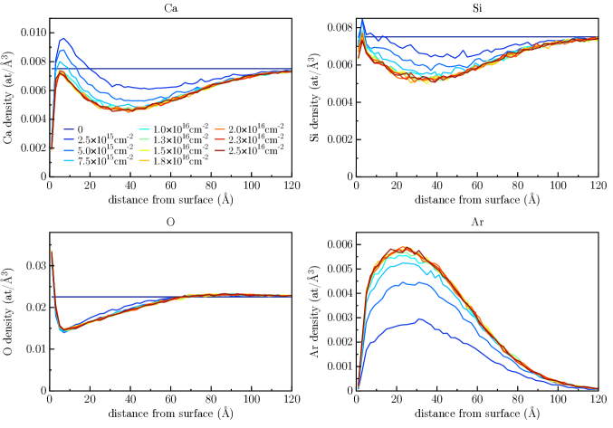
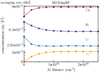
Figure 6 shows the average elemental concentration for the individual elements for increasing Ar sputtering fluence. The average is taken over 100 Å. In comparison to the experimental signal (cf. Fig. 1(b)), the rapid dynamics below Ar/cm2 cannot be captured, because surface contaminations are not included in SDTrimSP. For larger fluences the SDTrimSP simulations show a constant concentration for all elements, while the experiment shows some gradual increase of the Ca+Ar signal. This might result from additional implantation of Ar or rearrangement of implanted Ar, which can also not be captured properly with BCA codes.
In the SDTrimSP simulation we consider up to 20 at% Ar implantation, but we repeated the dynamic SDTrimSP simulation and suppressed Ar retention completely. The resulting elemental depth profiles served then as an input for IMINTDYN and the resulting, fitted, BCA spectrum is shown in Fig. 7. In this case the Ca peak is substantially lower than the experiment which indicates that there is indeed a substantial implantation of Ar into surface-near layers. However, due to uncertainties in a possibly different charge fraction from the different surface elements, we are not able to disentangle the pure Ar contribution to the Ca(+Ar) peak signal.