Event-based Motion-Robust Accurate Shape Estimation for Mixed Reflectance Scenes
Abstract.
Event-based structured light systems have recently been introduced as an exciting alternative to conventional frame-based triangulation systems for the 3D measurements of diffuse surfaces. Important benefits include the fast capture speed and the high dynamic range provided by the event camera - albeit at the cost of lower data quality. So far, both low-accuracy event-based as well as high-accuracy frame-based 3D imaging systems are tailored to a specific surface type, such as diffuse or specular, and can not be used for a broader class of object surfaces (”mixed reflectance scenes”). In this paper, we present a novel event-based structured light system that enables fast 3D imaging of mixed reflectance scenes with high accuracy. On the captured events, we use epipolar constraints that intrinsically enable decomposing the measured reflections into diffuse, two-bounce specular, and other multi-bounce reflections. The diffuse objects in the scene are reconstructed using triangulation. Eventually, the reconstructed diffuse scene parts are used as a ”display” to evaluate the specular scene parts via deflectometry. This novel procedure allows us to use the entire scene as a virtual screen, using only a scanning laser and an event camera. The resulting system achieves fast and motion-robust (14Hz) reconstructions of mixed reflectance scenes with accuracy. Moreover, we introduce a ”superfast” capture mode (250Hz) for the 3D measurement of diffuse scenes.
The novel method introduced that uses event cameras for triangulation and deflectometry is compared against commercial triangulation 3d scanner, time of flight camera, and state-of-the-art work.
1. Introduction
Shape estimation is an important task in computer vision pertinent to many fields like robotics, industrial inspection, autonomous navigation, augmented/mixed reality (AR/MR), and even consumer applications like face unlocking on smartphones. There are many light transport phenomena that occur in a scene with different objects and light sources, the most common being reflection, transmission, emission, and scattering. Depending on the reflectance properties of an object surface, some of these are more dominant than others. In a nearly opaque and diffuse material like wood, reflection and subsurface scattering are majorly evident whereas transmission and reflection dominate in a material like glass. Current state-of-the-art shape estimation methods are tailored toward imaging surfaces of specific reflectance properties like purely diffuse or purely specular. These techniques cannot be used in-the-wild on scenes with different types of object surfaces. Only a small class of object surfaces is purely diffuse or purely specular. Many of the existing methods suffer when measuring a scene consisting of partially specular object surfaces or a mix of diffuse and specular surfaces.
Our goal is to develop an imaging pipeline that is generalized and robust enough for the shape estimation of such scenes. Projecting light (structured or unstructured) onto such a scene leads to inter-reflection effects like specular reflections and subsurface scattering. Coding projected light patterns can be helpful in reducing the impact on diffuse object reconstruction (Gupta et al., 2011; O’Toole et al., 2015; Gupta et al., 2015). Another way is to use the geometry of the scene (epipolar constraints) to separate out the direct diffuse components from indirect illumination (OToole et al., 2016; Criminisi et al., 2005). One way to effectively use these constraints is to use a sparse scanning technique (like point or line projection) to limit the inter-reflections and the resulting signal ambiguities in the scene. For frame-based camera systems, this comes with the drawback of longer capture time, leading to motion artifacts.
Event cameras (Gallego et al., 2020; Lichtsteiner et al., 2008; Brandli et al., 2014; Posch et al., 2010) are differential cameras that are able to mitigate these drawbacks as they have extremely fast read-out for sparse changes in the scene. Event-based triangulation has been demonstrated for reconstructing diffuse scenes (Matsuda et al., 2015; Muglikar et al., 2021; Wang et al., 2020; Huang et al., 2021) in up to 16ms. In this paper, we tackle the challenging problem of fully capturing all objects in mixed reflectance scenes, i.e., scenes that simultaneously contain highly specular, highly diffuse, and shiny object surfaces. We use event-based scanning, separate out the diffuse and specular components using epipolar constraints, and reconstruct the scene in a two-step process starting with diffuse objects (using triangulation). The diffuse objects (plus background) in the entire scene are then used as a secondary illuminating source (a virtual screen) and the reflection of this virtual screen over the surface of all specular objects in the scene is observed. This forms the basis for a technique called deflectometry, which is used in the optical metrology community for ultra-high precision reconstruction of specular surfaces like lenses or technical parts.
Our novel approach combines the benefits of high-accuracy triangulation and deflectometry approaches, high-speed (14Hz up to 250Hz), and high pixel-resolution (1 megapixel), which eventually enables the motion-robust measurement of mixed reflectance scenes. To the best of our knowledge, a robust solution to this problem with high accuracy has not been demonstrated so far. Our paper presents the first step towards a novel concept that could potentially enable a new wave of 3D sensors. Imagine the measurement of real-life scenes like the interior of a car or a living room. These scenes have a mix of specular objects like mirrors, shiny displays, as well as diffuse objects like walls, cloth, and furniture. A 3D sensor that allows for the shape estimation of such scenes could potentially enable novel high-accuracy imaging applications in VR/MR, enabling users to precisely grasp small objects like a pen or button, or small robots or drones to navigate through the most crowded and complicated environments. It can also help in medical applications like enabling surgical machines to make accurate cuts even on shiny and moving objects like an open heart. Such scene-independent, high-speed, and precise 3D sensing has a broader impact, and stakeholders from different fields can profit from this.
Our contributions in this paper are:
-
•
One-fits-all solution: A high-resolution 3D imaging system that can reconstruct the shape of diffuse, specular, and partially specular objects at the same time without changing any system parameters.
-
•
Motion and ambient light robust system, imaging at 14Hz for mixed reflectance scenes and up to 250Hz for diffuse scenes in the presence of varying ambient light.
-
•
Novel dual-scanning laser projector for fast sparse scanning to enable direct-indirect illumination separation, eventually enabling specular shape estimation via deflectometry.
-
•
High accuracy: Quantitative analysis shows our method to perform with a depth error which is much lower than comparable state-of-the-art sensors.
2. Background and Related Work
| Method | Exposure | Depth Error | Scenes |
|---|---|---|---|
| Ensemble Codes[1] | 50 frames | 1.4 mm [1] | D |
| Kinect v2 ToF | 33 ms | 2 mm [2] | D |
| Intel Realsense | 33 ms | 1 cm [3] | D+PS |
| MC3D[4] | 16 ms | 8 mm [4] | D |
| ESL[5] | 16 ms | 7.8 mm [5] | D |
| Ours | 4-70 ms | ¡ 0.5 mm | D+S+PS |
Most state-of-the-art shape estimation techniques can be broadly classified into three categories (Häusler and Willomitzer, 2022): (a) triangulation-based principles (including passive and active stereo, light field imaging, depth from focus, or “structured light”, (b) reflectance based principles, that measure the surface gradient (such as photometric stereo, deflectometry, or polarization imaging), and (c) principles that measure the “time of flight” (ToF) or travel distance of light (including ToF cameras, Lidar, OCT, or interferometry). We discuss different measurement principles from these categories with respect to their ability to measure diffuse and /or specular object surfaces. Special attention is given to principles that can measure macroscopic objects with high accuracy.
2.1. Shape measurement of diffuse surfaces
Diffuse object surfaces scatter an incident light ray in multiple directions, meaning that a light signal reaching the surface can be “seen” and measured from multiple angles outside the angle of direct (specular) reflection. This is beneficial for 3d imaging, as surfaces with a broad variety of orientations can be measured with point light sources or projectors, i.e., sources where the light only comes from one single point. A special case of diffuse scattering is Lambertian scattering, where the surface appears equally bright from all directions and the brightness only depends on the angle of incidence of the light ray. This assumption forms the basis for Photometric Stereo (Woodham, 1979) or Shape from Shading (Zhang et al., 1999).
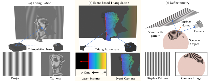
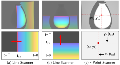
Similar brightness from multiple viewpoints is also useful for active or passive triangulation principles: Two cameras whose positions relative to each other are known, observe a point on the diffuse object surface. This forms a triangle with known angles and baseline, and the depth can be calculated by simple ray intersection. In active triangulation, patterns are projected onto the (possibly texture-less) object surface to obtain better correspondence between the cameras. The projector can also be calibrated as an inverse camera and can replace the second camera. Figure 2(a) shows an active triangulation system that uses a calibrated projector with one camera. The pattern projected onto the object’s surface looks deformed in the camera picture. The 3D shape is calculated from this deformation. The simplest form of active triangulation is (laser) point raster scanning: A single point is scanned over the object surface. For each time instance (e.g., camera image), the camera only observes one bright point, which directly delivers projector-camera correspondence free from any ambiguity. Over the years, different forms of active triangulation have been invented and developed. Many of them differ in the kind of patterns that are projected, which leads to benefits and drawbacks with respect to measurement speed, surface feature resolution, and size of the measurement volume (Geng, 2011). Examples include phase-measuring triangulation (Srinivasan et al., 1984), Fourier transform profilometry (Takeda and Mutoh, 1983), dense single-shot line triangulation (Willomitzer and Häusler, 2017; Willomitzer et al., 2013), single-photon structured light (Sundar et al., 2022), or hybrid methods (Mirdehghan et al., 2018).
In general, it can be said that denser patterns deliver higher point cloud densities, but are in turn more susceptible to correspondence ambiguities. Such ambiguities are commonly resolved by exploiting a temporal sequence of exposures (potentially not motion-robust), by using sophisticated spatial pattern codifications (possibly losing some high frequency details of the surface), or by exploiting prior knowledge about the scene, which includes recent learning-based methods (Zuo et al., 2022). Carefully implemented triangulation systems can measure diffuse surfaces of macroscopic objects with an impressive precision of hundreds or even tens of (CyberOptics, 2023). However, triangulation principles also have a weak spot: they fail to measure specular surfaces.
2.2. Shape measurement of specular surfaces
Specular surfaces like mirrors reflect an incident light ray only in one direction. This direction depends on the angle of incidence and the surface normal. For measurement principles like triangulation, ToF, or photometric stereo, the light only comes from one single point (such as the nodal point of a projector or a point light source). This means that a big portion of reflected light rays does not find its way back into the camera, which makes specular objects quasi “invisible” for these principles. It should be noted, however, that photometric stereo-based setups for the measurement of specular surfaces exist (Ikeuchi, 1981; Solomon and Ikeuchi, 1996). Nevertheless, these setups typically would require a large number of point light sources to be able to measure a high number of surface points, i.e., to achieve a good coverage of the surface.
An easy and intuitive way to increase the coverage for the active 3D measurement of specular surfaces is to increase the spatial (and angular) extent of the light source. This is the basic idea behind deflectometry, which is a well-known measurement principle in optical metrology (Knauer et al., 2004; Huang et al., 2018; Faber et al., 2012). Deflectometry setups commonly use a display (e.g., LCD screen) as a light source. The reflection of this display at the specular surface is observed with a camera (Figure 2(c)). From the deformation of the (known) display pattern in the camera image, the normal map of the specular object can be calculated. Eventually, the object shape can be retrieved by gradient integration methods like the Frankot-Chellappa algorithm (Frankot and Chellappa, 1988), or iterative surface integration methods (Huang and Asundi, 2012; Huang et al., 2015). Well-calibrated deflectometry setups can reach sub-micron depth resolution, which is the reason why deflectometry is widely used for industrial surface inspection of optical components (Shimizu et al., 2021; Knauer et al., 2004), to measure car bodies (Höfer et al., 2016), for cultural heritage (Willomitzer et al., 2020) or for eye surface measurement and tracking (Liang et al., 2016; Wang et al., 2023b, a). Since deflectometry uses an external display for projecting on a specular surface, it is an active imaging method. Passive specular reconstruction using environment maps has been shown before by Nishino and Nayar (2004), and more recently by Tiwary et al. (2023) using neural rendering techniques. These passive methods commonly require the scene to be sufficiently ”structured”, leading to low-quality results in dark or ”homogeneous-looking” environments.
In deflectometry, surface coverage for the measurement of specular objects is dependent on the object shape (e.g., convex, concave), as well as the size and standoff distance of the display. Increasing the coverage for complicated specular objects without using an elaborate dome arrangement is still a big problem for current state-of-the-art methods. A solution to this problem is one of the contributions of this paper.
2.3. Shape measurement of mixed reflectance scenes
All methods discussed above are tailored to the reflectance type of the target objects, i.e., they work best for purely diffuse or purely specular object surfaces. General “real-world” scenes, however, are composed of a mix of diffuse and specular objects. Many real-world object surfaces are not purely specular or purely diffuse, but rather “shiny” (partially specular) to a certain extent. Those objects are very hard to measure with conventional methods, and the results commonly leave much room for improvement. One reason is the vastly different signal return for the partially specular surfaces (very bright around direct reflection direction, very dim outside), which cannot be properly captured by the dynamic range of conventional cameras and leads to very different signal-to-noise ratios (SNRs). For the remainder of this paper, we refer to scenes composed of diffuse, specular, and partially specular (shiny) objects as mixed reflectance scenes. Previous work has attempted to estimate the shape of mixed reflectance scenes, e.g., by further extending diffuse triangulation-based methods Projecting structured light onto such a scene leads to unwanted inter-reflections due to specularities and scattering effects. One way to improve the measurement outcome is to separate these inter-reflections (the “indirect part”) from the diffuse components (the “direct part”). Gupta et al. (2011) design structured light patterns with high spatial frequencies to eliminate the indirect illumination effects in triangulation measurement.
This can also be done by exploiting epipolar constraints. The epipolar geometry (Szeliski, 2022) restricts the direct component reflection to a specific region of pixels on the image plane, and anything outside this region can be classified as indirect illumination. OToole et al. (2016) physically separate the components by using a rolling shutter camera with a rolling aperture projector. Extracting the direct components allows these methods to get the shape of the diffuse scene components. However, indirect reflections are rejected, and the shape of specular objects can not be recovered.
Another class of techniques combines deflectometry for specular shape measurement and structured light triangulation for diffuse shape measurement (Huang and Asundi, 2011; Liu et al., 2020). Their setup consists of a projector-camera system for triangulation and a LCD screen-camera system for deflectometry. Due to the combination of two principles, the method can measure diffuse and specular objects at the same time, but some fundamental problems discussed above remain: The coverage of specular objects is still dependent on the screen size, and large screens would be required for complicated objects, making the system impractical and increasing its cost.
3. Proposed Approach
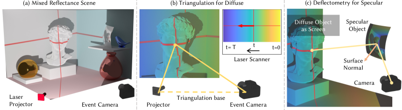
In our proposed solution approach, we combine triangulation and deflectometry in an unprecedented way and scan all components in mixed reflectance with only one single event-based measurement. Our setup consists only of an event camera and a scanning laser. The basic pipeline is shown in Figure 3. We scan the whole mixed reflectance scene with the laser and separate diffuse from specular scene contents using epipolar geometry. Eventually, we evaluate the 3D shape of the diffuse scene contents via triangulation. The specular scene contents are subsequently evaluated via deflectometry. However, instead of using an external screen for the deflectometry evaluation, we repurpose the just-evaluated 3D coordinates of the diffuse scene contents as a screen. One obvious benefit of this procedure is the low hardware and calibration effort: Only one camera and one scanning laser are needed, and no external screen. However, a more important benefit concerns the coverage of the specular objects in the scene: since everything around is a screen, there is virtually no restriction on screen size or angular coverage of specular objects. All diffuse objects in a room can be used as a screen!
3.1. Event-based 3D Scanning
As discussed, mixed reflectance scenes can cause multiple signal inter-reflections, which in turn can lead to severe signal ambiguities. Projecting sparse signals (ideally one single point) helps to mitigate those ambiguities. The ”classical” 3D imaging methods discussed in previous sections use frame-based cameras, which generate an image frame every few milliseconds. The inter-reflections in the scene prevent us from using single-shot methods, where only one projection and capture are required to recover the 3D information. “Multi-shot” imaging using sparse projections (e.g., point or line scanning) or novel multi-image projection schemes can be used to avoid artifacts caused by inter-reflections. However, acquiring multiple frames limits the capture speed and slows down the 3D imaging method.
In recent works, event cameras have been used to speed up the capture process for multi-shot principles (e.g., laser point raster scanning) (Matsuda et al., 2015; Muglikar et al., 2021). Event cameras are biologically inspired vision sensors that output a stream of events instead of complete image frames. Each pixel is triggered and read out only if its value changes by more than a set threshold. During read-out, the current timestamp and pixel position are noted, and these event tuples of (x pixel, y pixel, timestamp, polarity of change) form the event stream. This sparse read-out scheme of the event cameras allows imaging fast-changing scenes with latencies down to the order of 10 , depending on the sparsity of the events (Gallego et al., 2020). The differential nature of event cameras also drastically increases their dynamic range and robustness to ambient light with respect to frame-based cameras. In contrast, frame-based cameras require adjustment of exposure times for different lighting conditions and surface types.
So far, 3D imaging with event cameras has been mainly limited to event-based triangulation for diffuse surfaces. The basic idea is that multi-shot triangulation principles with sparse patterns (such as point raster scanning or line sweeping using lasers) can be significantly sped up by using a low latency event camera (Matsuda et al., 2015; Muglikar et al., 2021; Wang et al., 2020; Huang et al., 2021). Figure 2(b) depicts the basic principle. A correspondence between the projector and the camera pixels is obtained through the detected timestamps. This correspondence is then used for triangulation to get the depth of the pixel.
Our method uses a combination of two perpendicular line lasers to scan the scene by alternating between horizontal and vertical sweeps. We use these measurements to computationally treat this as an equivalent point scanning system, where each point’s information is obtained from both the vertical and horizontal scans, as shown in Figure 5. This gives us a big advantage over actually raster scanning the whole scene, which would be much slower (see Section 4.1). We note that a sweep in two directions is not necessary for triangulation on diffuse scenes because we can use a single line in conjunction with epipolar geometry for shape estimation. In contrast, as deflectometry is based on second-bounce indirect illumination, there is no epipolar constraint. A point scanning equivalent is thus essential for epipolar separation (Section 3.2), and deflectometry (Section 3.3). The high dynamic range of the event camera also improves the measurement of partially specular surfaces. For example, a low-intensity diffuse reflection from the surface is still sufficient to evaluate this surface in “triangulation mode”. In the following subsections, we give a detailed explanation of the steps involved in our approach.
3.2. Diffuse-Specular Separation
If the scene we measure is completely diffuse, then every generated event can be used for triangulation. As we try to generalize the types of measurable objects, we also encounter specular objects for which triangulation cannot be applied. We use triangulation for the diffuse reflections (Figure 3(b)) and deflectometry for the specular counterpart (Figure 3(c), Section 3.3). This requires us to separate the single-bounce diffuse (direct) reflections from multi-bounce specular (indirect) reflections.
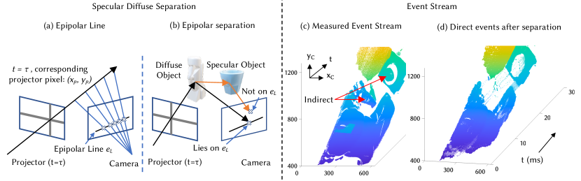
We exploit epipolar constraints for the separation of diffuse and specular components. Epipolar geometry describes the relation between two camera images in a triangulation (stereo vision) system. The relations also apply when one of the cameras is replaced with a projector, which is treated as an inverse camera. Figure 4(a) demonstrates the concept: for a particular projector pixel, the stereo geometry constrains the corresponding point on the camera plane to lie on a specific line - the epipolar line. These epipolar constraints can only be applied to the diffuse (direct) components of the scene, that is when the light from the projector reaches the camera through a single bounce. For multiple bounces (inter-reflections), this geometric constraint is not valid, as seen in Figure 4(b). In turn, this means that any point in the camera image which does not lie on its epipolar line must come from a multi-bounce reflection.
As discussed, our laser scanning approach is equivalent to lighting up one projector pixel at a time (albeit significantly faster). For each such projector pixel, we use its epipolar line to separate out the directly and indirectly illuminated pixels. OToole et al. (2016) demonstrated this principle to separate and visualize the direct and indirect components. This work classifies specular components, sub-surface scattering components, and inter-reflection components all as “indirect”. For our method, we additionally need to separate the specular components (to be evaluated with deflectometry) from the other indirect components. These are a specific set of two-bounce reflections that we need to filter out. Specifically, we ensure that the first bounce for these reflections comes from a diffuse surface, and the second one from the specular surface, exactly as seen in Figure 4(b). This can be done by recovering the direct component using epipolar separation, and then the other component captured in the camera plane is its corresponding reflection from the specular surface. This is then used for deflectometry, where the direct component forms the screen for the specular surface reflection.
Measurement of diffuse and partially specular regions.
After separating the reflection components, we use event-based triangulation on the diffuse parts, as described in Section 3.1. Some objects like a ceramic bowl show both diffuse and specular reflections. For a particular pixel covering this object, it might get a diffuse reflection for some timestamp and specular for another. In such cases, we classify that pixel as diffuse and reject its specular component. We then use triangulation for its shape estimation as we do for all the diffuse components. We can do this because of the high dynamic range of the event camera, as we still get a good signal if we only evaluate the (sometimes very dim) diffuse component. This is another benefit of using event cameras.
3.3. Everything Around is a Screen
Deflectometry for specular scene parts.
A standard deflectometry system consists of a screen, the specular object to be measured, and the camera. The screen and the camera position are calibrated with respect to each other before the measurement. When measuring the normals (and later the shape) of a specular surface, first the correspondence between screen coordinates and camera pixels is determined. In other words, for each camera pixel that observes the specular object surface, we need to know the 3D coordinate of the corresponding point on the screen that illuminates the specular object. In our proposed approach, we already have those corresponding “3D screen coordinates” as they are nothing but the 3D coordinates of the diffuse scene parts and have been calculated in the previous step (see Figure 3). Thus any diffuse surfaces in the scene can be used as a screen for the shape estimation of specular surfaces. As this removes the necessity of a separate screen for deflectometry, everything around can be treated as a screen!
This approach has several advantages over conventional deflectometry systems. First, no additional “screen calibration” is necessary, as the screen coordinates are automatically obtained from the triangulation evaluation step. A second advantage is that we can theoretically create arbitrary large screens (consisting potentially of entire rooms) to significantly improve the coverage of specular surfaces. The idea of using everything around as a screen was explored before in the context of display systems, where arbitrarily shaped objects could be measured and used as displays from given user perspectives (Raskar et al., 1998; Raskar, 2002).
Getting the exact correspondence between the camera and screen coordinates is necessary for deflectometry. This would not be possible if we just used a line-scanning projector, where a specular surface pixel would ambiguously map to several diffuse screen coordinates. As discussed before, point scanning is especially helpful in this case as the number of signal ambiguities is significantly decreased, and specular surfaces can be mapped to their corresponding diffuse screen points. Getting this accurate correspondence gives us an estimate of the surface normals (Figure 3(c)). To calculate the shape of the specular objects from the measured normals, we integrate the normal map with an iterative shape reconstruction algorithm (Huang and Asundi, 2012) that alternately estimates normals from a shape estimate, and then improves shape estimate by integrating the normals. This process goes on until the shape converges.
We combine the diffuse and specular surface reconstructions to get the shape estimate of a mixed reflectance scene. We emphasize at this point that, to the best of our knowledge, our system also shows the concept of event-based deflectometry for the first time. Naïve event-based deflectometry can be achieved by displaying a moving pattern (point, line, etc.) on an LCD screen, or by projecting the moving pattern on a planar screen or a wall. Such procedures can be seen as a subset of our method, and we already achieve more by using arbitrary scenes of different shapes as screen.
4. Experimental setup & Implementation
4.1. Laser scanning procedure
We model and calibrate the projector as an inverse camera (see Section 4.3). Each projector pixel is represented by two timestamps of the event stream (one for x, one for y). For better robustness, we choose a coarser pixelation (801x801), meaning that each projector pixel is represented by a set of timestamps from the event stream. The size of this set depends on the scanning speed of the projector. Slower scanning means a collection of events from a larger bucket of event timestamps and faster scanning implies fewer events for each pixel. For the pixels on the camera that (a) correspond to these timestamps and (b) are located on the respective epipolar line, we evaluate the respective 3D coordinate via standard triangulation by intersecting the ray from the camera pixel with the projector ray as shown in Figure 3(b). We emphasize that the above pixelation is chosen for convention and does not restrict our lateral point cloud resolution to 801x801 as we can generate sub-projector-pixels too.
For reasons discussed above (e.g., ambiguity), our proposed algorithms work best for laser point raster scanning. However, point scanning is elaborate and slower compared to line scanning (even if event cameras are used), and motion-robust imaging can potentially not be achieved. To facilitate fast, efficient, and accurate scanning, we develop a novel dual-scan laser projector that can be algorithmically converted to a point raster scanner.
We use a galvo scanner combined with a crosshair () laser diode that projects two perpendicular lines. In its initial position, the crossing point is located in the lower right corner of the field of view. For a full scan, we sweep the () laser pattern first to the left (until the crossing point reaches the lower left corner), and then up (until the crossing point reaches the upper left corner). As shown in Figure 5, this is equivalent to sweeping a vertical and horizontal laser line subsequently. Eventually, a laser point raster scan can be algorithmically emulated, by just considering all possible crossing points of the vertical and horizontal line.
Compared to a point raster scan, this procedure can be performed significantly faster. Assuming a squared field of view, where the galvo scanner requires a time for one single vertical or horizontal pass, a full scan with our procedure is completed in , while point raster scanning would take (without considering additional delays for stop and go).
Although the scan is continuous, we choose to assign discrete projector pixels to the laser scanner: We utilize the high-precision event timestamps recorded by the event camera for synchronization, meaning that our system identifies projector pixels based on recorded event timestamps. The horizontal sweep of the vertical arm (Figure 5(a)) gives us the x-pixel of the projector , and the horizontal arm (Figure 5(b)) similarly gives us the y-pixel . In the camera image, the generated events’ positions are intersected to get the exact camera pixel corresponding to the projector pixel (Figure 5(c)).
The discussed treatment of the camera-projector correspondence gives us four major benefits: (1) We can use standard camera-projector triangulation frameworks that assume discrete projector pixels. (2) More accurate calibration. As opposed to previous event-based triangulation methods, we calibrate the projector by using a relatively slow scan speed. This mitigates any effect of event noise on the calibration. The final evaluation scans can be done extremely fast and the calibration noise is not carried over. (3) The point scanner treatment lets us exercise epipolar constraints for each projector pixel more effectively and enables us to separate diffuse and specular scene components. (4) It enables point-wise correspondence which is extremely beneficial in the case of deflectometry.
4.2. Hardware
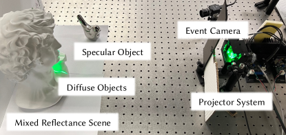
Figure 6 shows our experimental setup in action while imaging a scene with a diffuse and a specular object. We use a Prophesee EVK4 event camera that has a resolution of 720 1280 pixels. Our projection system consists of a CivilLaser 520nm, 80mW crosshair laser diode and a galvo scanner (Thorlabs GVS012) scanning with two cross-axis scanning mirrors that are controlled by a Digital Acquisition Board (National Instruments DAQ PCIe 6363) through the galvo drivers.
4.3. System Calibration
Accurate system calibration is very important for the success of our proposed method as it directly affects the accuracy of our results. This section discussed the details of the calibration process of all involved components.
Intrinsic Event Camera Calibration
The circuitry of an event camera is designed to allow only differences in the scene to be detected. Despite this, their pixel arrangement and optics are similar to that of frame-based cameras. The latter allows us to apply existing camera calibration algorithms directly to event cameras (Zhang, 2000) if we can generate the respective calibration images. For the commonly used calibration method by Zhang (2000), we need to generate images of a known checkerboard at various positions within the measurement volume of the camera. For a static checkerboard in a static scene, the event camera would generate no output. For this reason, we capture “images” of the checkerboard by illuminating the scene with a pico-projector that uses a laser scanner internally. By adjusting the bias/threshold parameters of the event camera, we allow more events in the white region and fewer in the black (just for calibration purposes). The laser scanner then accordingly generates events as it moves across the checkerboard. Eventually, the camera events of several such illumination cycles are averaged together to form one “checkerboard image”. This means that such an image is generally very low noise, and the SNR can be improved by increasing the number of illumination cycles for one image. Multiples of these images are created at different positions and fed into the calibration algorithm to obtain the intrinsic camera parameters.
Projector - Camera Synchronization
When we scan the scene with the laser projector, events are generated that are recorded by the event camera in the form of (x pixel, y pixel, timestamp) tuples. These timestamps are the connection of the camera with the projector and allow us to get correspondence between projector pixels and camera pixels. Since we control the galvo scanning of the projector, we know exactly which timestamp corresponds to which position of the “projector pixel”. However, to pass this information to the camera, the start time of the projector scan has to be known precisely. This can be either done through an electronic trigger or through generating external synchronization events before the actual scan to get the scan start time. Electronic triggers sometimes result in drift due to noise and event bus saturation, which can lead to inaccurate detection. We thus get the start timestamp by generating events through the laser precisely a few milliseconds (= known offset) before the actual scan starts. These synchronization events are detected by the camera, and the detected average timestamp plus the known offset gives us a very precise estimate of the scan start time.
Camera-Projector calibration
As discussed, we model the projector as an inverse camera which allows us to use standard stereo triangulation algorithms (Feng et al., 2021) and deflectometry algorithms (Huang and Asundi, 2012) for depth estimation. The respective calibration steps work as follows: we use the previously described checkerboard pattern that is placed at different positions in the measurement volume. We obtain the projector calibration parameters by projecting our dual-scan line pattern onto the checkerboard for each position. The overlap of checker patterns and projected signal allows us to convert each of the detected checkerboard corners from camera pixels to projector pixels. This enables us to calibrate the projector as an inverse camera.
5. Results
Scene Setup. We calibrate the scene in a volume of . In that volume, we place many different diffuse, specular, and shiny objects. The projector scans through this whole scene and our method detects the shape of the object surfaces. Our system is tested against varying ambient lighting conditions to test the robustness of our method. We also quantitatively evaluate the performance of our system for both specular and diffuse object reconstructions.
5.1. Imaging Mixed Reflectance Scenes
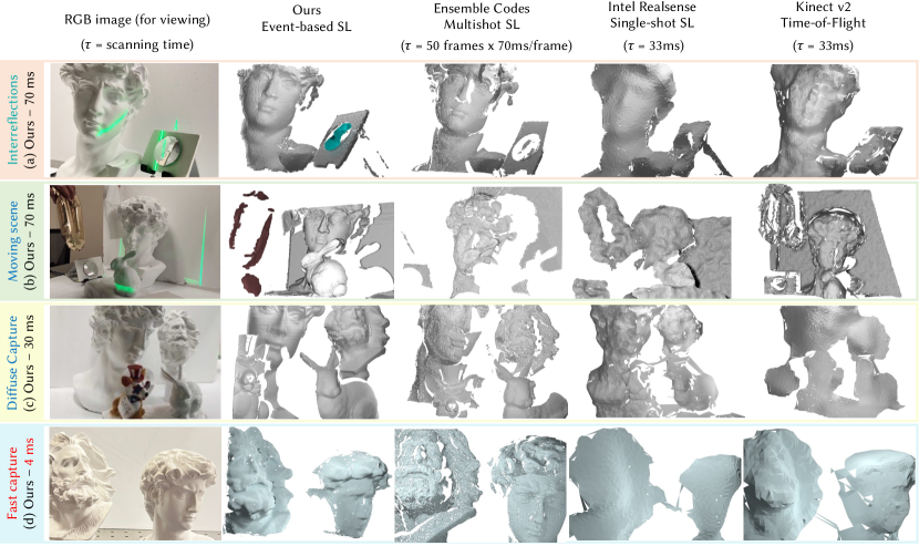
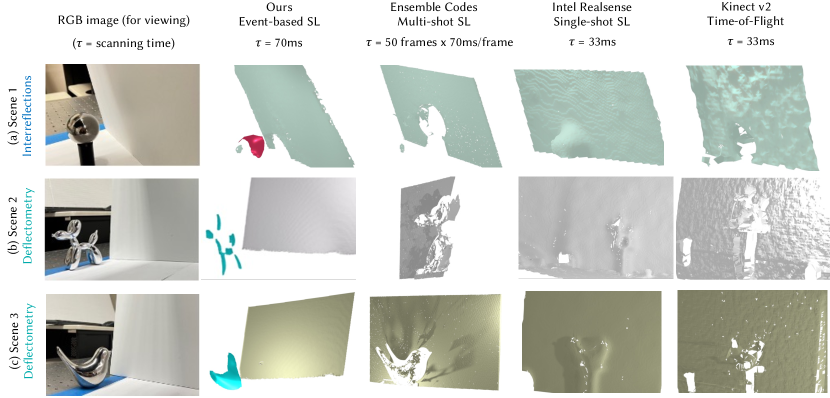
Figures 8 and 1 show the results on a variety of scenes and compares the reconstruction of our method against the following state-of-the-art and commercial baselines: (1) Structured light in the presence of global illumination using Ensemble Codes (Gupta et al., 2011), (2) Intel RealSense D435i™ triangulation camera, and (3) Microsoft Kinect™ v2 Time-of-Flight (ToF) depth sensor. We compare against the Ensemble Codes (Gupta et al., 2011) method because, although published more than 10 years ago, it still represents the state-of-the-art performance of projector-based triangulation systems for shape estimation in the presence of indirect illumination. The use of ensemble codes suppresses inter-reflections in the scene, and the use of triangulation provides a high-resolution shape estimation for the diffuse parts of the scene. We compare against Intel RealSense and Kinect v2 ToF sensor as they are two of the most popular commercial solutions for depth estimation and rely on two fundamentally different measurement principles.
Ensemble Codes method Gupta et al. (2011) requires 50 frames to be projected and captured. Although the actual operating speed depends on the projector and camera used, it can be said that it is very hard to achieve motion robust performance with this method. For the implemention of the method with our hardware (FLIR BFS-U3-19S4C camera and Viewsonic X11-4K projector), a good SNR in every single image was reached for 70ms per frame, resulting in a total capture time of per 3D view. The Intel RealSense and Kinect v2 ToF were both operated at their default frame rates of 30Hz (33ms per 3D view). As discussed previously, our method scans the scene first by sweeping a horizontal line laser and then a vertical one. We achieve good SNR values for a 30ms scan in each direction. We also add a 5ms ”recovery time” between each scan to prevent any possible noisy events that might occur towards the start or end of a scan. This results in scan time per 3D view, allowing us to do video capture at a frame rate of about 14Hz. We found empirically that a faster scan time would reduce the possibility of detection of secondary reflections from specular surfaces. The scanning time can be further reduced if we use a higher-power laser source.
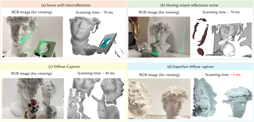
Scenes 1,2 in Figure 7, and Scenes 1-3 in Figure 8 are 70ms scans for our method, and demonstrate our system’s ability to image mixed reflectance surfaces. Scene 1 in Figure 7 consists of a specular object (a convex mirror) and a diffuse object (a David bust). This scene causes multiple inter-reflections when light is projected on it. Our method is able to reconstruct both the diffuse (in gray) and specular (in blue) parts accurately. Moreover, the radius of curvature of the reconstructed mirror is accurately retrieved (see Section 5.3). The Ensemble Codes method is not able to reconstruct the specular surface and also has some artifacts near the left eye of David. We observe that the diffuse part of the scene is reconstructed with very high quality with Ensemble Codes and our method, with Ensemble Codes slightly beating ours owing to the frame-based camera which has four times the number of pixels and has longer capture time leading to a better signal-to-noise-ratio in comparison. RealSense and Kinect v2 detect the presence of the mirror but do not match the expected shape, up to a point where it is not clear if the 3D data at the mirror position are caused by an artifact or are the actual estimation or the mirror’s shape. Both commercial sensor concepts also reconstruct the diffuse part with visibly much lower quality.
Scene 2 in Figure 7 consists of a stationary specular mirror, a partially specular balloon (in motion), and diffuse objects - David bust, Stanford bunny, and a moving paper towel. Our method performs an accurate 14Hz reconstruction of the moving scene with mixed reflectance objects (see video here). We evaluate the shiny balloon and the convex mirror with deflectometry and the rest of the diffuse objects with triangulation. Notice the motion-robust reconstruction of both the balloon and the small mirror in the scene along with the diffuse Stanford bunny, David statue, and a part of the moving paper towel. Ensemble Codes gets the diffuse reconstruction of only the objects that do not move (it misses the moving paper towel), and, as expected, it misses all the specular parts of the scene. RealSense and Kinect on the other hand are motion robust and perform a lower quality shape estimation of diffuse objects as well as the balloon (which is also partially diffuse), but fail in getting the shape of the mirror.
Similar trends can be observed in the scenes shown in Figure 8: Scene 1 in Figure 8 shows another scene with multiple interreflections caused by a specular ball bearing. Our method uses both the direct reflections from the ball bearing as well as the secondary deflectometry reflections, hence constructing the illuminated parts of the ball. We observe that such spherical objects are hardest to reconstruct as they reflect a quasi 360∘ view of the environment, and would ideally require the whole room to be used as screen. RealSense detects the specular object but fails to accurately reconstruct it, whereas Ensemble Codes and Kinect both miss the specular parts. Scene 2, and 3 in Figure 8 show event deflectometry, where we use a diffuse surface (a plane) in the scene to get the shape of the specular surfaces. The shapes of the balloon dog in Scene 2 and the metal bird in Scene 3 are reconstructed accurately along with the diffuse reconstruction of the plane. As seen previously, Ensemble Codes misses the specular parts. RealSense performs a low-quality reconstruction of specular surfaces while Kinect misses on them.
5.2. Imaging Diffuse Scenes
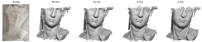
In special cases where we already know that the scene has just diffuse objects, we can just use a single sweep scan instead of dual scanning. This allows us to reduce the scanning time by a factor of 2x without any loss in the reconstruction quality of diffuse scenes. A comparison of our 30ms reconstruction is shown in Scene 3 of Figure 7. Our method achieves better data quality than the 3.5s ensemble code scan, and much better data quality than Kinect and RealSense. As no (weak) 2-bounce reflections have to be detected anymore for purely diffuse scenes, we can further decrease the time for a single sweep. In our prototype setup, we were able to reduce the capture time to only 4ms (!), while still achieving high-quality reconstructions. A comparison of our superfast capture with SOTA is shown in the last row of Figure 7. Although not as good as the 3.5s ensemble code scan and our 70ms scan, our fast 4ms scan still shows a much higher quality than RealSense or Kinect. This is another indication of the great potential of our novel method - even if only ”standard” diffuse scenes are measured. In Scene 3 and 4 of Figure 7, and Figure 9 we show scanning of diffuse objects at different speeds, from 30ms per scene to up to 4ms per frame or 250Hz. To the best of our knowledge, this is the fastest scanning shown for an event-based structured light system. We note that we can use a much faster triangulation scheme in place of Ensemble Codes when the scene is known to be diffuse but the quality would essentially be the same. In Scene 4 of Figure 1, we demonstrate the shape estimation of the diffuse scene in just 4 ms. For the same scene, the commercial cameras - RealSense, and Kinect perform reconstruction with much poorer reconstruction in a scan time of 30ms.
5.3. Quantitative evaluation
We evaluate the accuracy and precision of our method by measuring different objects with known sizes or shapes. For the evaluation of our triangulation reconstruction, we measured a sphere with a diffuse surface and well-known () radius, as well as a precisely manufactured diffuse planar surface. The scan time for all our evaluation measurements was 70 ms. To evaluate how accurately our method reconstructs the object shape, we compare our evaluated point cloud with the respective ground truth shape. For the measurement of the planar surface, we obtain as the root-mean-square error (RMSE) with respect to the planar ground truth shape. The RMSE of the sphere data with respect to the spherical ground truth shape is evaluated to . To evaluate the precision of our triangulation reconstruction we isolate the statistical noise on our data by subtracting a low-frequency best-fit surface from our obtained point cloud and eventually evaluate the standard deviation of the remaining 3D noise. The so-obtained precision of the plane measurement is and the precision of the sphere measurement is .
The accuracy and precision of our deflectometry reconstruction is evaluated in a similar fashion, by measuring a specular sphere with known radius (also ). The diffuse planar surface described above is used as a screen for our deflectometry measurement (setup similar to the specular ball in Scene 1 of Figure 8). We emphasize again that a ”deflectometry measurement” with our method always includes a concurrent shape estimation of the diffuse ”screen scene parts” (diffuse planar surface in this case). This estimation is also subject to uncertainty (see error values above for comparison), which propagates into the deflectometry measurement. After automated rejection of outliers in the deflectometry reconstruction outside the -intervall ( of data) the RMSE with respect to the specular ground truth shape is calculated to and the respective precision to .
For both specular and diffuse reconstructions, Table 1 reveals that our achieved depth error values (all ) outperform the previously discussed SOTA methods. An additional comparison with MC3D (Matsuda et al., 2015) and ESL (Muglikar et al., 2021) (both being limited to purely diffuse surfaces) reveals that the accuracy of our method is, to the best of our knowledge, unprecedented in the field of event-based shape estimation of macroscopic objects.
To put our results in the larger context of even more SOTA 3D imaging principles, we emphasize again that standard (frame-based) triangulation and deflectometry methods used in optical metrology can still easily achieve depth errors comparable or even lower than ours. However, as discussed, this lower error comes at the price of triangulation and deflectometry being locked to either purely diffuse of purely specular surfaces, paired with limited flexibility and long capture times that do not allow for motion-robust measurements in many cases.
5.4. Motion Robust Capture
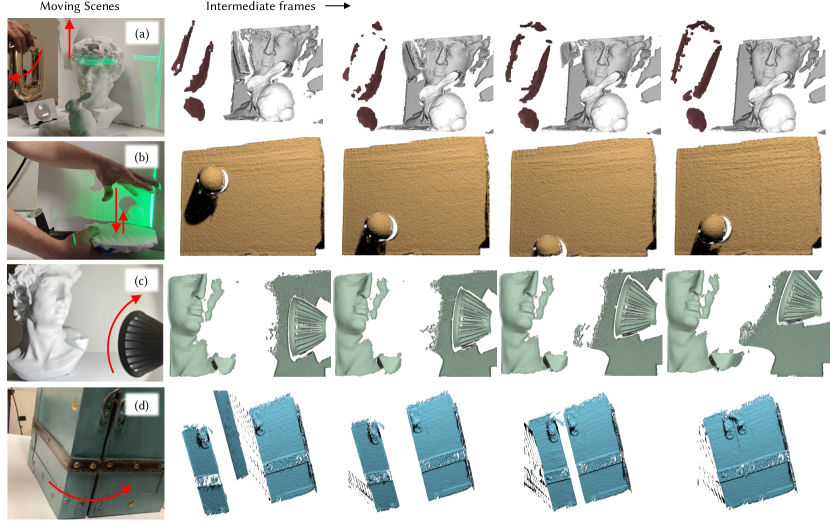
One of the biggest advantages of our system is fast high-quality capture which allows for motion robust reconstructions of moving mixed reflectance scenes (mixed reflectance 3D videos). Representative frames of these videos for four different scenes are shown in Figure 10, and the full videos can be seen here. The first scene shows the reconstruction for the combination of specular and diffuse objects - a shiny balloon and a convex mirror, and some diffuse objects (David and Stanford Bunny). The moving scene is reconstructed in a 14Hz (70ms per frame) video. The second, third, and fourth scenes are reconstructed at 29Hz (35ms per frame), assuming the presence of only diffuse and partially specular objects in the scene. The second scene shows a table tennis ball bouncing while the third video demonstrates the ambient light resilience of our system. For this third video, we move a bright light bulb rapidly which changes the lighting of the scene. However, this does not affect our results leading to the successful reconstruction of both the side of the bulb as well as the David statue. The fourth scene shows a treasure chest with partially specular surfaces like the metal strip and handle. Our method is able to successfully reconstruct these partially specular parts too.
Conclusion and Discussion
We show a novel pipeline for 3D imaging scenes that have a mix of diffuse and specular objects. The low depth error of our captured data is unprecedented in the SOTA of event-based shape estimation of macroscopic objects. Compared to other approaches, our method is more generalized and shows better performance in terms of dynamic range and motion robustness. Our dual scanning approach also improves the diffuse reconstruction and the results are comparable to high-accuracy frame-based camera triangulation setups - an achievement that has not been demonstrated before for event cameras. We also show the reconstruction of specular objects that are indirectly illuminated by the diffuse object screens, eliminating the need for separate deflectometry screens. We believe this approach has the potential to become a widely used high-precision, generalized, and motion-robust 3D scanning system in the future.
However, our current approach is not without limitations: In special cases and for complicated specular objects to be measured, some inter-reflections might also occasionally fall on the epipolar line of our camera, leading to an artifact. Although very rare, this problem can be solved in future setups by adding an additional camera that resolves the remaining ambiguities. Moreover, the polarization of the illumination can be exploited as well to solve this problem.
Although significantly mitigated by our novel method, the incomplete coverage provided by the ”screen” also still remains a problem for the deflectometry measurement of complex specular surfaces. In an ideal case, the whole surrounding (like a complete room) should be used as a screen, which would require different/additional hardware (such as a rotating room laser scanner) to be implemented in a concrete experiment. Nevertheless, our paper shows a first proof of principle that lays out a clear path for its extension towards larger ”room-screens”, potentially leading to the effective adoption of our technology, e.g., in AR/VR, medical imaging, or industrial inspection.
Acknowledgements
This work was supported by NSF award 2153516. We thank Mohit Gupta for providing the code for the Ensemble Codes (Gupta et al., 2011) method which we used for the state-of-the-art comparisons.
References
- (1)
- Bamji et al. (2014) Cyrus S Bamji, Patrick O’Connor, Tamer Elkhatib, Swati Mehta, Barry Thompson, Lawrence A Prather, Dane Snow, Onur Can Akkaya, Andy Daniel, Andrew D Payne, et al. 2014. A 0.13 m CMOS system-on-chip for a 512 424 time-of-flight image sensor with multi-frequency photo-demodulation up to 130 MHz and 2 GS/s ADC. IEEE Journal of Solid-State Circuits 50, 1 (2014), 303–319.
- Brandli et al. (2014) Christian Brandli, Raphael Berner, Minhao Yang, Shih-Chii Liu, and Tobi Delbruck. 2014. A 240 180 130 db 3 s latency global shutter spatiotemporal vision sensor. IEEE Journal of Solid-State Circuits 49, 10 (2014), 2333–2341.
- Criminisi et al. (2005) Antonio Criminisi, Sing Bing Kang, Rahul Swaminathan, Richard Szeliski, and P Anandan. 2005. Extracting layers and analyzing their specular properties using epipolar-plane-image analysis. Computer vision and image understanding 97, 1 (2005), 51–85.
- CyberOptics (2023) CyberOptics. 2023. Surveyor DS-Series, High Precision Design and Accuracy. https://www.cyberoptics.com/download/industrial-metrology/laser-scanners/DS-SERIES-8026994-REV_D.pdf. [Accessed 14-11-2023].
- Faber et al. (2012) Christian Faber, Evelyn Olesch, Roman Krobot, and Gerd Häusler. 2012. Deflectometry challenges interferometry: the competition gets tougher!. In Interferometry XVI: Techniques and Analysis, Joanna Schmit, Katherine Creath, Catherine E. Towers, and Jan Burke (Eds.), Vol. 8493. International Society for Optics and Photonics, SPIE, San Diego, CA, USA, 84930R. https://doi.org/10.1117/12.957465
- Feng et al. (2021) Shijie Feng, Chao Zuo, Liang Zhang, Tianyang Tao, Yan Hu, Wei Yin, Jiaming Qian, and Qian Chen. 2021. Calibration of fringe projection profilometry: A comparative review. Optics and lasers in engineering 143 (2021), 106622.
- Frankot and Chellappa (1988) Robert T. Frankot and Rama Chellappa. 1988. A method for enforcing integrability in shape from shading algorithms. IEEE Transactions on pattern analysis and machine intelligence 10, 4 (1988), 439–451.
- Gallego et al. (2020) Guillermo Gallego, Tobi Delbrück, Garrick Orchard, Chiara Bartolozzi, Brian Taba, Andrea Censi, Stefan Leutenegger, Andrew J Davison, Jörg Conradt, Kostas Daniilidis, et al. 2020. Event-based vision: A survey. IEEE transactions on pattern analysis and machine intelligence 44, 1 (2020), 154–180.
- Geng (2011) Jason Geng. 2011. Structured-light 3D surface imaging: a tutorial. Advances in optics and photonics 3, 2 (2011), 128–160.
- Gupta et al. (2011) Mohit Gupta, Amit Agrawal, Ashok Veeraraghavan, and Srinivasa G Narasimhan. 2011. Structured light 3D scanning in the presence of global illumination. In CVPR 2011. IEEE, 713–720.
- Gupta et al. (2015) Mohit Gupta, Shree K Nayar, Matthias B Hullin, and Jaime Martin. 2015. Phasor imaging: A generalization of correlation-based time-of-flight imaging. ACM Transactions on Graphics (ToG) 34, 5 (2015), 1–18.
- Häusler and Willomitzer (2022) Gerd Häusler and Florian Willomitzer. 2022. Reflections about the holographic and non-holographic acquisition of surface topography: where are the limits? Light: Advanced Manufacturing 3, 2 (2022), 226–235.
- Höfer et al. (2016) Sebastian Höfer, Jan Burke, and Michael Heizmann. 2016. Infrared deflectometry for the inspection of diffusely specular surfaces. Advanced Optical Technologies 5, 5-6 (2016), 377–387.
- Huang and Asundi (2011) Lei Huang and Anand Asundi. 2011. Study on three-dimensional shape measurement of partially diffuse and specular reflective surfaces with fringe projection technique and fringe reflection technique. In Dimensional Optical Metrology and Inspection for Practical Applications, Vol. 8133. SPIE, 24–30.
- Huang and Asundi (2012) Lei Huang and Anand Asundi. 2012. Improvement of least-squares integration method with iterative compensations in fringe reflectometry. Applied optics 51, 31 (2012), 7459–7465.
- Huang et al. (2018) Lei Huang, Mourad Idir, Chao Zuo, and Anand Asundi. 2018. Review of phase measuring deflectometry. Optics and Lasers in Engineering 107 (2018), 247–257.
- Huang et al. (2015) Lei Huang, Mourad Idir, Chao Zuo, Konstantine Kaznatcheev, Lin Zhou, and Anand Asundi. 2015. Comparison of two-dimensional integration methods for shape reconstruction from gradient data. Optics and Lasers in Engineering 64 (2015), 1–11.
- Huang et al. (2021) Xueyan Huang, Yueyi Zhang, and Zhiwei Xiong. 2021. High-speed structured light based 3D scanning using an event camera. Optics Express 29, 22 (2021), 35864–35876.
- Ikeuchi (1981) Katsushi Ikeuchi. 1981. Determining surface orientations of specular surfaces by using the photometric stereo method. IEEE Transactions on Pattern Analysis and Machine Intelligence 6 (1981), 661–669.
- Intel (2023) RealSense Intel. 2023. Depth Camera D435i — intelrealsense.com. https://www.intelrealsense.com/depth-camera-d435i/. [Accessed 08-11-2023].
- Knauer et al. (2004) Markus C Knauer, Jurgen Kaminski, and Gerd Hausler. 2004. Phase measuring deflectometry: a new approach to measure specular free-form surfaces. In Optical Metrology in Production Engineering, Vol. 5457. SPIE, 366–376.
- Kurillo et al. (2022) Gregorij Kurillo, Evan Hemingway, Mu-Lin Cheng, and Louis Cheng. 2022. Evaluating the accuracy of the Azure Kinect and Kinect v2. Sensors 22, 7 (2022), 2469.
- Liang et al. (2016) Hanning Liang, Evelyn Olesch, Zheng Yang, and Gerd Häusler. 2016. Single-shot phase-measuring deflectometry for cornea measurement. Advanced Optical Technologies 5, 5-6 (2016), 433–438.
- Lichtsteiner et al. (2008) Patrick Lichtsteiner, Christoph Posch, and Tobi Delbruck. 2008. A 128 128 120 dB 15 s latency asynchronous temporal contrast vision sensor. IEEE journal of solid-state circuits 43, 2 (2008), 566–576.
- Liu et al. (2020) Xiaohong Liu, Zonghua Zhang, Nan Gao, and Zhaozong Meng. 2020. 3D shape measurement of diffused/specular surface by combining fringe projection and direct phase measuring deflectometry. Optics Express 28, 19 (2020), 27561–27574.
- Matsuda et al. (2015) Nathan Matsuda, Oliver Cossairt, and Mohit Gupta. 2015. MC3D: Motion contrast 3d scanning. In 2015 IEEE International Conference on Computational Photography (ICCP). Houston, TX, USA, 1–10.
- Mirdehghan et al. (2018) Parsa Mirdehghan, Wenzheng Chen, and Kiriakos N Kutulakos. 2018. Optimal structured light a la carte. In Proceedings of the IEEE Conference on Computer Vision and Pattern Recognition. 6248–6257.
- Muglikar et al. (2021) Manasi Muglikar, Guillermo Gallego, and Davide Scaramuzza. 2021. ESL: Event-based structured light. In 2021 International Conference on 3D Vision (3DV). IEEE, 1165–1174.
- Nishino and Nayar (2004) Ko Nishino and Shree K Nayar. 2004. Eyes for relighting. ACM Transactions on Graphics (TOG) 23, 3 (2004), 704–711.
- O’Toole et al. (2015) Matthew O’Toole, Supreeth Achar, Srinivasa G Narasimhan, and Kiriakos N Kutulakos. 2015. Homogeneous codes for energy-efficient illumination and imaging. ACM Transactions on Graphics (ToG) 34, 4 (2015), 1–13.
- OToole et al. (2016) M. OToole, J. Mather, and K. N. Kutulakos. 2016. 3D Shape and Indirect Appearance by Structured Light Transport. IEEE Transactions on Pattern Analysis and Machine Intelligence 38, 07 (jul 2016), 1298–1312. https://doi.org/10.1109/TPAMI.2016.2545662
- Posch et al. (2010) Christoph Posch, Daniel Matolin, and Rainer Wohlgenannt. 2010. A QVGA 143 dB dynamic range frame-free PWM image sensor with lossless pixel-level video compression and time-domain CDS. IEEE Journal of Solid-State Circuits 46, 1 (2010), 259–275.
- Raskar (2002) Ramesh Raskar. 2002. Projector-Based Three Dimensional Graphics. Ph. D. Dissertation. University of North Carolina at Chapel Hill.
- Raskar et al. (1998) Ramesh Raskar, Greg Welch, Matt Cutts, Adam Lake, Lev Stesin, and Henry Fuchs. 1998. The office of the future: A unified approach to image-based modeling and spatially immersive displays. In Proceedings of the 25th annual conference on Computer graphics and interactive techniques. 179–188.
- Shimizu et al. (2021) Yuki Shimizu, Liang-Chia Chen, Dae Wook Kim, Xiuguo Chen, Xinghui Li, and Hiraku Matsukuma. 2021. An insight into optical metrology in manufacturing. Measurement Science and Technology 32, 4 (2021), 042003.
- Solomon and Ikeuchi (1996) Fredric Solomon and Katsushi Ikeuchi. 1996. Extracting the shape and roughness of specular lobe objects using four light photometric stereo. IEEE Transactions on Pattern Analysis and Machine Intelligence 18, 4 (1996), 449–454.
- Srinivasan et al. (1984) Venugopal Srinivasan, Hsin-Chu Liu, and Maurice Halioua. 1984. Automated phase-measuring profilometry of 3-D diffuse objects. Applied optics 23, 18 (1984), 3105–3108.
- Sundar et al. (2022) Varun Sundar, Sizhuo Ma, Aswin C Sankaranarayanan, and Mohit Gupta. 2022. Single-Photon Structured Light. In Proceedings of the IEEE/CVF Conference on Computer Vision and Pattern Recognition. 17865–17875.
- Szeliski (2022) Richard Szeliski. 2022. Computer vision: algorithms and applications. Springer Nature.
- Takeda and Mutoh (1983) Mitsuo Takeda and Kazuhiro Mutoh. 1983. Fourier transform profilometry for the automatic measurement of 3-D object shapes. Applied optics 22, 24 (1983), 3977–3982.
- Tiwary et al. (2023) Kushagra Tiwary, Akshat Dave, Nikhil Behari, Tzofi Klinghoffer, Ashok Veeraraghavan, and Ramesh Raskar. 2023. ORCa: Glossy Objects as Radiance-Field Cameras. In Proceedings of the IEEE/CVF Conference on Computer Vision and Pattern Recognition.
- Wang et al. (2023b) Jiazhang Wang, Tianfu Wang, Bingjie Xu, Oliver Cossairt Willomitzer, et al. 2023b. Accurate Eye Tracking from Dense 3D Surface Reconstructions using Single-Shot Deflectometry. arXiv preprint arXiv:2308.07298 (2023).
- Wang et al. (2023a) Tianfu Wang, Jiazhang Wang, Oliver Cossairt, and Florian Willomitzer. 2023a. Optimization-Based Eye Tracking using Deflectometric Information. arXiv preprint arXiv:2303.04997 (2023).
- Wang et al. (2020) Zihao W Wang, Peiqi Duan, Oliver Cossairt, Aggelos Katsaggelos, Tiejun Huang, and Boxin Shi. 2020. Joint filtering of intensity images and neuromorphic events for high-resolution noise-robust imaging. In Proceedings of the IEEE/CVF Conference on Computer Vision and Pattern Recognition. 1609–1619.
- Willomitzer et al. (2013) Florian Willomitzer, Svenja Ettl, Oliver Arold, and Gerd Häusler. 2013. Flying triangulation-A motion-robust optical 3D sensor for the real-time shape acquisition of complex objects. In AIP Conference Proceedings, Vol. 1537. American Institute of Physics, 19–26.
- Willomitzer and Häusler (2017) Florian Willomitzer and Gerd Häusler. 2017. Single-shot 3D motion picture camera with a dense point cloud. Optics express 25, 19 (2017), 23451–23464.
- Willomitzer et al. (2020) Florian Willomitzer, Chia-Kai Yeh, Vikas Gupta, William Spies, Florian Schiffers, Aggelos Katsaggelos, Marc Walton, and Oliver Cossairt. 2020. Hand-guided qualitative deflectometry with a mobile device. Optics express 28, 7 (2020), 9027–9038.
- Woodham (1979) Robert J Woodham. 1979. Photometric stereo: A reflectance map technique for determining surface orientation from image intensity. In Image understanding systems and industrial applications I, Vol. 155. SPIE, 136–143.
- Zhang et al. (1999) Ruo Zhang, Ping-Sing Tsai, James Edwin Cryer, and Mubarak Shah. 1999. Shape-from-shading: a survey. IEEE transactions on pattern analysis and machine intelligence 21, 8 (1999), 690–706.
- Zhang (2000) Zhengyou Zhang. 2000. A flexible new technique for camera calibration. IEEE Transactions on pattern analysis and machine intelligence 22, 11 (2000), 1330–1334.
- Zuo et al. (2022) Chao Zuo, Jiaming Qian, Shijie Feng, Wei Yin, Yixuan Li, Pengfei Fan, Jing Han, Kemao Qian, and Qian Chen. 2022. Deep learning in optical metrology: a review. Light: Science & Applications 11, 1 (2022), 39.