Entangling gates on degenerate spin qubits dressed by a global field
Abstract
Semiconductor spin qubits represent a promising platform for future large-scale quantum computers owing to their excellent qubit performance Xue2022 ; Noiri2022 ; madzik2022 , as well as the ability to leverage the mature semiconductor manufacturing industry for scaling up zwanenburg2013 ; zwerver2022 ; Gonzalez2021 . Individual qubit control, however, commonly relies on spectral selectivity Veldhorst2014 ; fogarty2018integrated ; takeda2016fault , where individual microwave signals of distinct frequencies are used to address each qubit. As quantum processors scale up, this approach will suffer from frequency crowding, control signal interference and unfeasible bandwidth requirements. Here, we propose a strategy based on arrays of degenerate spins coherently dressed mollow1969 ; xu2007 ; Baur2009 ; Londonn2013 by a global control field hansen2022 ; Seedhouse2021 and individually addressed by local electrodes. We demonstrate simultaneous on-resonance driving of two degenerate qubits using a global field while retaining addressability for qubits with equal Larmor frequencies. Furthermore, we implement SWAP oscillations during on-resonance driving, constituting the demonstration of driven two-qubit gates. Significantly, our findings highlight how dressing can overcome the fragility of entangling gates between superposition states Petit2022 ; Petta2005 ; Simmons2019 ; Guo2023 and increase their noise robustness. These results constitute a paradigm shift in qubit control in order to overcome frequency crowding in large-scale quantum computing.
In the race towards building a large-scale universal quantum computer, we are faced with several potential future bottlenecks. The fragility of qubits is a commonly discussed aspect as current quantum error correction codes, essential for fault tolerant quantum computing, only allow for very small error rates fowler2012 . The scaling prospect is also of utmost importance, since the number of required physical qubits is expected to exceed millions. Challenges include routing of necessary control signals onto the quantum processor chip franke2019rent , control signal interference, variability, Cifuentes2023 etc. Scaling up current architectures by brute force will present many challenges and is not necessarily the best course of action.00footnotetext: ∗ i.hansen@unsw.edu.au00footnotetext: † a.dzurak@unsw.edu.au00footnotetext: ‡ henry.yang@unsw.edu.au
Global control was suggested by Kane in 1998 kane1998 and involves globally applying a single microwave field to an array of qubits. Recent advancements have demonstrated a version where the qubits are by-default on resonance Seedhouse2021 ; hansen2022 ; Hansen2021 . Dressed qubits are continuously decoupled from low-frequency noise and individually addressed by local electrodes laucht2017dressed ; hansen2022 . Furthermore, the global field can be generated off-chip vahapoglu ; vahapoglu2022 , which frees up space on the chip and simplifies control signal routing. Therefore, a global control scheme based on dressed degenerate qubits tackles the fragility of qubits while offering a prospect for scalability. Additional advantages include reduced control bandwidths and control signal interference.
In this work, we demonstrate two crucial components of the vision to operate dressed degenerate qubits in a global field, namely single-qubit addressability and two-qubit operation. We tune two silicon metal-oxide-semiconductor (SiMOS) quantum dot spin qubits (see Extended data Fig. 1) such that their Larmor and Rabi frequencies are matched, and then perform single- and two-qubit universal dressed control in a global field.
Degenerate spins in a global dressing field
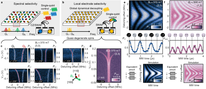
Traditionally, qubits are addressed by their individual Larmor frequencies using spectral selectivity Veldhorst2014 ; fogarty2018integrated ; takeda2016fault , as illustrated in Fig. 1(a). To avoid interference between different control signals, this strategy requires a spread of Larmor frequencies in excess of the Rabi frequency. The Larmor frequency of a qubit is set by the Bohr magneton, the static magnetic field strength and the -factor. The latter has a natural variability in Si/SiO2 devices ( MHzT) due to spin-orbit coupling Veldhorst2014 ; tanttu2019 ; harvey2019spin ; Cifuentes2023 ; Martinez2022 . Nanomagnets resulting in a slanted field can also be used such that qubits in different locations see different magnetic field strengths Tokura2006 ; philips2022 ; Takeda2021 ; pioro2008electrically . With these aforementioned strategies one can control a handful of qubits philips2022 ; Takeda2021 ; Lawrie2023 ; Hendrickx2021 ; Lawrie2020 . However, when scaling up to millions of qubits, frequency crowding will become a problem Jones2018 ; Seedhouse2021 . Moreover, due to the distribution of Larmor frequencies, the native two-qubit gate between neighbouring spins, which is a function of the Larmor frequency difference and the exchange magnitude, varies between controlled-Z (CZ) and SWAP Meunier2011 .
The aim of a global control strategy using dressed qubits is to have arrays of quasi-degenerate spins that can be driven on-resonance by a global microwave field and addressed individually by local electrodes, as illustrated in Fig. 1(b). This approach circumvents the problem of frequency crowding and control signal interference when scaling up. Conveniently, the SWAP gate is the native two-qubit gate for quasi-degenerate spins due to the small Larmor frequency differences Meunier2011 .
To drive multiple qubits with a global field, it is favourable for the qubits to be uniform, and it has been shown recently that the variability of SiMOS spin qubits caused by the roughness of the Si/SiO2 interface is bounded Cifuentes2023 . The -factor variability is expected to be % for a DC magnetic field applied along the [100] direction and the robust control protocol introduced in Refs. Hansen2021, ; hansen2022, and employed in Ref. vallabhapurapu2023high, is designed to handle this bounded variability.
Here, we mimic the behaviour of a global control field with an electron-spin-resonance (ESR) antenna and therefore have to carefully match the Larmor and Rabi frequencies. The qubit Larmor frequencies must all be within the linewidth of the global microwave field in order to achieve on-resonance driving and the Rabi frequencies must be similar, so that the qubits follow the same clock cycle. A sizeable Stark shift from the top gates on the Larmor frequencies is also important for addressability.
Larmor frequency matching
The -factor variability from spin-orbit interactions can be minimised by pointing the static magnetic field along instead of the default direction tanttu2019 ; Cifuentes2023 . The magnetic field orientation can also reduce the qubit susceptibility to charge noise and potentially increase tanttu2019 ; Ferdous2018 . Although this strategy is useful for matching the Larmor frequencies of two qubits, one can not rely on this alone when scaling up to larger numbers of qubits. Using low static magnetic field strength is also beneficial for the qubit uniformity fogarty2018integrated , as the Larmor frequency variability is directly proportional to the -factor times the static magnetic field (). Applying large microwave powers increases the Rabi frequency, and therefore also increases the tolerable spread of qubit Larmor frequencies.
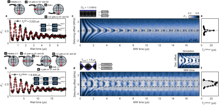
By ramping the voltage detuning between quantum dots at a determined rate, we initialise the system in the spin state, facilitated by the fact that near the charge transition the spins are not yet entirely degenerate. We then study the voltage dependence of the qubit frequencies by performing slow chirped microwave pulses, which adiabatically invert the spin state if its resonance frequency is contained within the range of the chirp lauchtadb2014 . This is verified by measuring the probability that the final spin state is blockaded, as plotted in Fig. 1(c).
Adiabatic spin inversions as a function of VJ1 with different static magnetic field angles are shown. At , near the orientation, the two qubits are quasi-degenerate. Note that after this angle, the order of the qubit frequencies inverts and therefore the initialisation also inverts, resulting in the reflection of the branching of the frequencies as a function of VJ1. In Fig. 1(d) a high-resolution version of the quasi-degenerate case is shown with Larmor frequencies around 10.362 GHz, separated by kHz. This small difference in Larmor frequency is achieved by pointing the static magnetic field along [100], which minimises the Dresselhaus spin-orbit coupling, and using a relatively low magnetic field strength of 370 mT.
The difference between spin Zeeman energies, combined with other parameters, is known to shift the outcome of the spin blockade from a singlet-triplet (ST) readout to a parity readout Seedhouse2021_0 . In the present case, the state is mapped into the unblockaded singlet through an adiabatic ramp in some configurations (which we refer to as adiabatic ST), while in others any odd-parity state ends up equally unblockaded (see Supplementary material). Once the operational parameters are settled, a characterisation is required to distinguish between the two scenarios.
Rabi frequency matching
When the Larmor frequencies of two qubits match, as demonstrated at low VJ1 in Fig. 1(d), they can be driven simultaneously with a global field. The resulting Rabi frequency is set by the power delivered to the qubits from the microwave source, through the on-chip ESR antenna. Due to the transmission characteristics of the ESR antenna, the power delivered into the device varies as a function of microwave frequency (and therefore the Rabi frequency depends on the choice of ). Moreover, the Rabi frequencies of the two qubits are not necessarily equal. Besides the inhomogeneity of the oscillatory magnetic field generated by the antenna geometry, both qubits can be affected by the spurious electric component of the microwave field Gilbert2023 . This electric drive is usually minimised through the choices of double-dot electrostatic potential confinement, static magnetic field strength and orientation.
The only scalable way to address this variability in Rabi frequency is to engineer the microwave field to have minimal electric component. In the particular case of two qubits, however, we can tolerate the stray electric fields by fine-tuning the magnetic field strength until the Rabi frequencies of both qubits match. We find both Larmor frequency matching and Rabi frequency () matching with values 10.362 GHz and 1 MHz, respectively, at 370 mT. The Larmor frequencies are different by of and the Rabi frequencies by of . These conditions lead to qubit rotations that are sufficiently synchronous to consider the two qubits simultaneously driven with a shared clock (and any deviations are considered coherent errors in the qubit operations).
In Fig. 1(e) a Rabi chevron is shown for two qubits with matched Larmor and Rabi frequencies in the adiabatic ST readout regime with initialisation. The same is shown in Fig. 1(f) for the parity readout regime with initialisation. The adiabatic ST readout yields a periodic oscillation at the Rabi frequency but it is not a simple sinusoidal because only the is unblockaded, while the driving populates all states. The parity readout regime gives oscillations at twice the frequency and half the amplitude when initialised in , due to and both being unblockaded (see Supplementary material). All the following measurements are done using initialisation and the adiabatic ST readout regime.
By leveraging advanced microwave engineering and a dielectric resonator or a cavity as the microwave source in the future, increasing the magnitude and uniformity of the magnetic field, the matching conditions for Larmor and Rabi are not expected to present a significant challenge.
Entanglement during on-resonance driving
The fundamental interaction between spins is the spherically symmetric Heisenberg exchange coupling . In the particular case of non-degenerate spin qubits, the Larmor frequency difference creates an effective Ising coupling , which favours the implementation of CZ gates. In the case of degenerate qubits the full Heisenberg interaction naturally leads to SWAP gates instead, as originally proposed by Loss and DiVincenzo Meunier2011 ; Seedhouse2021 ; Loss1998 ; Petta2005 ; Simmons2019 ; Petit2022 .
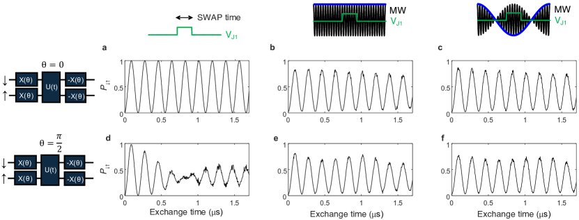
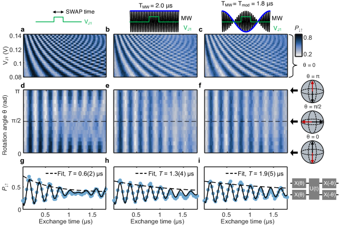
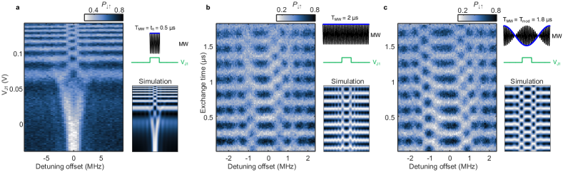
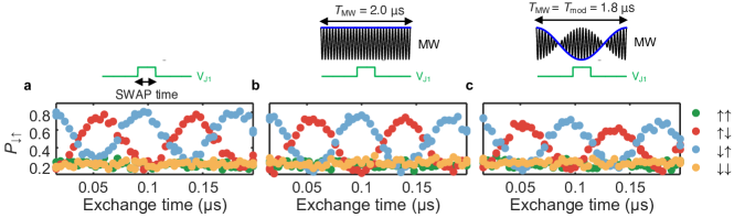
A voltage pulse applied to gate J1 (see Extended data Fig. 1) turns the exchange interaction on and off, showing SWAP oscillations over time in Fig. 2(a) as a function of VJ1. The fastest SWAP oscillation recorded here is ns, limited by the voltage range of the equipment (see Methods). Differently from the case of CZ, where a strong exchange coupling leads to deviations from the idealised Ising model, here the stronger the exchange further accentuates the Heisenberg interaction.
We repeat the same entangling pulse measurement in the case when a microwave on resonance with both qubits is applied with either a constant power or with a sinusoidal modulation, shown in Fig. 2(b-c) respectively. Note that the VJ1 pulse is centred within the microwave pulse. The microwave pulse duration is fixed to ensure that it effectively performs an identity gate. We find that the SWAP oscillations remain unchanged during microwave driving but lose some visibility, which we attribute to degradation of the SET charge readout caused by heating. The sinusoidal modulated driving is found to be more robust against Larmor frequency variability (see Extended data Fig. 2).
In Fig. 2(d-f) we showcase the most important result in this work, that the SWAP oscillations between superposition states Sigillito2019 are significantly more preserved for driven qubit implementations than for bare qubits. Looking at the experiment in Fig. 2(a-c) this point is missed because the SWAP oscillations between the states and are not exposed to decoherence times the whole time. However, SWAP oscillations between the more relevant states reveal the true impact of decoherence on these states and the benefits of dynamical decoupling.
We repeat the measurement with initial states varying continuously from () to () with a microwave pulse to rotate the qubits before a fixed VJ1 pulse and undo the rotation at the end. For initialisations around , the driven SWAP oscillations remain coherent for longer than in the undriven case. This can be explained by noise decoupling Watson2018 ; Xue2022 ; Huang2023 resulting from the driving field hansen2022 . Crucially, our results draw attention to the fragility of entangling gates between arbitrary superposition states (as opposed to eigenstates, see Extended data Fig. 3), which are typically not studied in literature Guo2023 ; Petit2022 ; Petta2005 ; Simmons2019 . In Fig. 2(g-i), the oscillations for initialisation in [dotted line at in Fig. 2(d-f)] are compared. Being able to perform SWAP/ on arbitrary states with high fidelity is not only important in universal quantum computing for implementing two-qubit computational gates, but also in the context of coherent quantum state transfer Jones2018 .
Joint coherence metrics
In Fig. 3(a-b) free-induction decay and Hahn echo measurements are performed. In the context of simultaneously driven qubits, however, these experiments must be reinterpreted. The joint probabilities oscillate [similar to Fig. 1(e)] because the recovery gate is applied at an angle increasing with wait time in regard to the preparation gate (these oscillations are introduced to improve the fitting accuracy, see Supplementary material). The decay of these oscillations is the joint decay rate of the two spins, which are simultaneously prepared in superposition states and . If the decoherence processes are completely independent, both the free-induction and Hahn echo decays are expected to be twice as fast as the conventional single-qubit measurements. We extract µs and µs, where the superscript 2Q refers to the fact that both qubits are involved in the dephasing.
In Fig. 3(c-d) we show the driven two-qubit oscillations over time as a function of the microwave frequency in the case of optimally matched Larmor and Rabi frequencies. The constant power case [Fig. 3(c)] is the same experiment as shown before in Fig. 1(e), but now with sufficiently long times to observe the decay of the driven qubits. The horizontal dashed lines indicate the range of detunings that yield µs. This arbitrary reference line gives an indication of the tolerance of this type of driven qubit to uncertainties in the qubit frequency, which in this case is approximately 230 kHz.
In Fig. 3(d) the microwave is amplitude-modulated with a sinusoid according to Ref. Hansen2021, , using the same average microwave power as in Fig. 3(c). The period of the sinusoidal modulation is set to the theoretical optimal µs, which is determined by the Rabi frequency obtained at this set power hansen2022 (see Supplementary materials). Comparing the range between the dashed lines in this modulated case (approximately 1.27 MHz) we can see a five-fold improvement in tolerance for the qubit detuning. This is further emphasized in the fitted Rabi coherence times plotted in Fig. 3(e-f).
The sinusoidal modulation improves the tolerance of the architecture to the variability in Larmor frequencies for large arrays of spin qubits and also offers protection against microwave amplitude errors. This was predicted from theory in Ref. Hansen2021, .
Addressability of quasi-degenerate spins
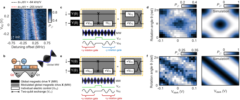
Individual control of driven qubits is achieved by dynamically shifting the qubit frequency leveraging the Stark effect created by the voltage bias at the top gate that forms the dot laucht2017dressed ; Hansen2021 ; hansen2022 . In the case of two neighbouring qubits, the small separation between dots leads to crosstalk effects, whereby the frequency of a qubit is affected by the top gate of the neighbouring dot as well Cifuentes22023 . In the general case, this leads to the requirement for simultaneous pulsing on both gates to address one of the qubits without affecting the other.
SiMOS spin qubits are known to exhibit weak spin-orbit coupling, which is further minimised by pointing the static magnetic field along [100] tanttu2019 . While this is advantageous to achieve degeneracy between the spins, it also impacts the magnitude of the Stark shifts from the top gates Cifuentes2023 ; tanttu2019 . Fortunately, only a small shift ( of ) is required for qubit control. In fact, too large shifts would cause the rotating wave approximating (RWA) to break laucht2016b , and moreover, would leave the qubits more susceptible to electrical noise. In this device we are able to Stark shift Q2 by kHz using gate P2 in Fig. 4(a), compared to a Rabi frequency of 1 MHz.
We find that the effect of gate P2 on Q2 is times stronger than on Q1. This strong differential Stark shift control is sufficient to achieve good addressability of Q2. We note that the inverse was not true and we did not perform operations using P1. Instead, we perform all single qubit gates in the same dot using P2 only and perform SWAP operations to address both qubits. In Fig. 4(c-d) individual control of both qubits is shown with positive -rotation on Q1 and negative -rotation on Q2 for different P2 voltage amplitudes and different initial states. The initial state is determined by a microwave pulse applied to the degenerate qubits in the state, similar to what was done in Fig. 2(d-f). In Fig. 4(e-f) the same sequence is used but with positive rotations on both qubits. Together, the data in Fig. 4 (c,d) and (e,f) demonstrate universal single-qubit control.
Conclusion
We have shown that two degenerate spins can be driven synchronously with a single global field and universally controlled electrically by local electrodes. This represents an alternative control strategy tackling the inevitable problem of frequency crowding in large arrays of spins. The spins are continuously decoupled from environmental noise by driving them on-resonance throughout any computation. We find that the driving is particularly important during entangling gates between spin states that are exposed to dephasing. In summary, this work represents a paradigm shift in qubit control strategies using dressed degenerate spins for noise-robust and scalable universal control.
References
References
- (1) Xue, X. et al. Quantum logic with spin qubits crossing the surface code threshold. Nature 601, 343–347 (2022).
- (2) Noiri, A. et al. Fast universal quantum gate above the fault-tolerance threshold in silicon. Nature 601, 338–342 (2022).
- (3) Mądzik, M. T. et al. Precision tomography of a three-qubit donor quantum processor in silicon. Nature 601, 348–353 (2022).
- (4) Zwanenburg, F. A. et al. Silicon quantum electronics. Rev. Mod. Phys. 85, 961–1019 (2013).
- (5) Zwerver, A. M. J. et al. Qubits made by advanced semiconductor manufacturing. Nature Electronics 5, 184–190 (2022).
- (6) Gonzalez-Zalba, M. F. et al. Scaling silicon-based quantum computing using cmos technology. Nature Electronics 4, 872–884 (2021).
- (7) Veldhorst, M. et al. An addressable quantum dot qubit with fault-tolerant control-fidelity. Nature Nanotechnology 9, 981–985 (2014).
- (8) Fogarty, M. et al. Integrated silicon qubit platform with single-spin addressability, exchange control and single-shot singlet-triplet readout. Nature communications 9, 4370 (2018).
- (9) Takeda, K. et al. A fault-tolerant addressable spin qubit in a natural silicon quantum dot. Science advances 2, e1600694 (2016).
- (10) Mollow, B. R. Power spectrum of light scattered by two-level systems. Phys. Rev. 188, 1969–1975 (1969).
- (11) Xu, X. et al. Coherent optical spectroscopy of a strongly driven quantum dot. Science 317, 929–932 (2007).
- (12) Baur, M. et al. Measurement of autler-townes and mollow transitions in a strongly driven superconducting qubit. Physical Review Letters 102, 243602 (2009).
- (13) London, P. et al. Detecting and polarizing nuclear spins with double resonance on a single electron spin. Phys. Rev. Lett. 111, 067601 (2013).
- (14) Hansen, I. et al. Implementation of an advanced dressing protocol for global qubit control in silicon. Applied Physics Reviews 9, 031409 (2022).
- (15) Seedhouse, A. E. et al. Quantum computation protocol for dressed spins in a global field. Physical Review B 104, 235411 (2021).
- (16) Petit, L. et al. Design and integration of single-qubit rotations and two-qubit gates in silicon above one kelvin. Communications Materials 3, 82 (2022).
- (17) Petta, J. R. et al. Coherent manipulation of coupled electron spins in semiconductor quantum dots. Science 309, 2180–2184 (2005).
- (18) He, Y. et al. A two-qubit gate between phosphorus donor electrons in silicon. Nature 571, 371–375 (2019).
- (19) Ni, M. et al. A SWAP gate for spin qubits in silicon. Preprint at arXiv https://arxiv.org/pdf/2310.06700.pdf (2023).
- (20) Fowler, A. G., Mariantoni, M., Martinis, J. M. & Cleland, A. N. Surface codes: Towards practical large-scale quantum computation. Physical Review A 86, 032324 (2012).
- (21) Franke, D. P., Clarke, J. S., Vandersypen, L. M. & Veldhorst, M. Rent’s rule and extensibility in quantum computing. Microprocessors and Microsystems 67, 1–7 (2019).
- (22) Cifuentes, J. D. et al. Bounds to electron spin qubit variability for scalable CMOS architectures. Preprint at arXiv https://doi.org/10.48550/arXiv.2303.14864 (2023).
- (23) Kane, B. E. A silicon-based nuclear spin quantum computer. Nature 393, 133–137 (1998).
- (24) Hansen, I. et al. Pulse engineering of a global field for robust and universal quantum computation. Physical Review A 104, 062415 (2021).
- (25) Laucht, A. et al. A dressed spin qubit in silicon. Nature Nanotechnology 12, 61–66 (2017).
- (26) Vahapoglu, E. et al. Single-electron spin resonance in a nanoelectronic device using a global field. Science Advances 7, eabg9158 (2021).
- (27) Vahapoglu, E. et al. Coherent control of electron spin qubits in silicon using a global field. npj Quantum Information 8, 126 (2022).
- (28) Tanttu, T. et al. Controlling spin-orbit interactions in silicon quantum dots using magnetic field direction. Physical Review X 9, 021028 (2019).
- (29) Harvey-Collard, P. et al. Spin-orbit interactions for singlet-triplet qubits in silicon. Physical Review Letters 122, 217702 (2019).
- (30) Martinez, B. & Niquet, Y.-M. Variability of electron and hole spin qubits due to interface roughness and charge traps. Physical Review Applied 17, 024022 (2022).
- (31) Tokura, Y., van der Wiel, W. G., Obata, T. & Tarucha, S. Coherent single electron spin control in a slanting zeeman field. Physical Review Letters 96, 047202 (2006).
- (32) Philips, S. G. J. et al. Universal control of a six-qubit quantum processor in silicon. Nature 609, 919–924 (2022).
- (33) Takeda, K. et al. Quantum tomography of an entangled three-qubit state in silicon. Nature Nanotechnology 16, 965–969 (2021).
- (34) Pioro-Ladriere, M. et al. Electrically driven single-electron spin resonance in a slanting zeeman field. Nature Physics 4, 776–779 (2008).
- (35) Lawrie, W. I. L. et al. Simultaneous single-qubit driving of semiconductor spin qubits at the fault-tolerant threshold. Nature Communications 14, 3617 (2023).
- (36) Hendrickx, N. W. et al. A four-qubit germanium quantum processor. Nature 591, 580–585 (2021).
- (37) Lawrie, W. I. L. et al. Spin relaxation benchmarks and individual qubit addressability for holes in quantum dots. Nano Letters 20, 7237–7242 (2020).
- (38) Jones, C. et al. Logical qubit in a linear array of semiconductor quantum dots. Physical Review X 8, 021058 (2018).
- (39) Meunier, T., Calado, V. E. & Vandersypen, L. M. K. Efficient controlled-phase gate for single-spin qubits in quantum dots. Physical Review B 83, 121403 (2011).
- (40) Vallabhapurapu, H. H. et al. High-fidelity control of a nitrogen-vacancy-center spin qubit at room temperature using the sinusoidally modulated, always rotating, and tailored protocol. Physical Review A 108, 022606 (2023).
- (41) Ferdous, R. et al. Interface-induced spin-orbit interaction in silicon quantum dots and prospects for scalability. Physical Review B 97, 241401 (2018).
- (42) Laucht, A. et al. High-fidelity adiabatic inversion of a 31P electron spin qubit in natural silicon. Applied Physics Letters 104, 092115 (2014).
- (43) Seedhouse, A. E. et al. Pauli blockade in silicon quantum dots with spin-orbit control. PRX Quantum 2, 010303 (2021).
- (44) Gilbert, W. et al. On-demand electrical control of spin qubits. Nature Nanotechnology 18, 131–136 (2023).
- (45) Loss, D. & DiVincenzo, D. P. Quantum computation with quantum dots. Physical Review A 57, 120–126 (1998).
- (46) Sigillito, A. J., Gullans, M. J., Edge, L. F., Borselli, M. & Petta, J. R. Coherent transfer of quantum information in a silicon double quantum dot using resonant SWAP gates. npj Quantum Information 5, 110 (2019).
- (47) Watson, T. F. et al. A programmable two-qubit quantum processor in silicon. Nature 555, 633–637 (2018).
- (48) Huang, J. Y. et al. High-fidelity operation and algorithmic initialisation of spin qubits above one kelvin. Preprint at arXiv https://arxiv.org/pdf/2308.02111.pdf (2023).
- (49) Cifuentes, J. D. et al. Impact of electrostatic crosstalk on the spin qubits of dense CMOS architectures. Preprint at arXiv https://arxiv.org/pdf/2309.01849.pdf (2023).
- (50) Laucht, A. et al. Breaking the rotating wave approximation for a strongly driven dressed single-electron spin. Physical Review B 94, 161302 (2016).
- (51) Tanttu, T. et al. Stability of high-fidelity two-qubit operations in silicon. Preprint at arXiv https://arxiv.org/pdf/2303.04090.pdf (2023).
- (52) Yang, C. H. et al. Operation of a silicon quantum processor unit cell above one kelvin. Nature 580, 350–354 (2020).
Methods
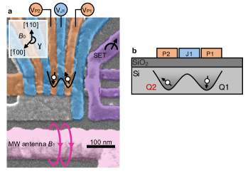
Experimental setup. The SiMOS quantum dot device is fabricated using 800 ppm isotopically purified 28Si with a gate stack of Al/AlOx oxide. It is the same device as device A in Ref. Tanttu2023, operated in isolated mode, that is, electrically isolated from the nearby electron reservoirs. The electron configuration is (3,3), except for Fig. 1(f) which is (1,3). The two dots are formed under gates P1 and P2. The gate J1 is used to control the exchange coupling between the spins. A global field is generated with an on-chip ESR antenna. Spin information is read out with a single-electron-transistor (SET) using Pauli spin blockade (PSB).
The experiments are done in an Oxford Kelvinox 400HA dilution refrigerator. DC bias voltages are coming from Stanford Research Systems SIM928 Isolated Voltage Sources. Gate pulse waveforms are generated with a Quantum Machines (QM) OPX+ and combined with DC biases using custom linear bias combiners at room temperature. The SET current is amplified using a room temperature I/V converter (Basel SP983c) and sampled by a QM OPX+. The microwave pulses are generated with a Keysight PSG8267D Vector Signal Generator, with I/Q and pulse modulation waveforms generated from the QM OPX+. The vector magnet is an Oxford instruments MercuryiPS.
The only feedback protocol used in this work is on the SET top gate, monitoring the current ISET to maintain maximum sensitivity.
Interleaved measurements. The data displayed in Fig. 2(a-c), Fig. 2(d-f), Fig. 2(g-i) and Fig. 3(c-d) are all taken in an interleaved manner including two or three data sets. An interleaved measurement protocol involves acquiring a single data point for each data set before stepping the measurement parameters so that data points are acquired for each data set sequentially. This reduces temporal bias when trying to make a fair comparison between data sets.
Data availability
All data of this study will be made available in an online repository.
Code availability
The analysis codes that support the findings of the study are available from the corresponding authors on reasonable request.
Acknowledgments
We acknowledge support from the Australian Research Council (FL190100167 and CE170100012), the U.S. Army Research Office (W911NF-23-10092) and the NSW Node of the Australian National Fabrication Facility. The views and conclusions contained in this document are those of the authors and should not be interpreted as representing the official policies, either expressed or implied, of the Army Research Office or the U.S. Government. The U.S. Government is authorised to reproduce and distribute reprints for Government purposes notwithstanding any copyright notation herein. I.H., A.E.S., S.S., M.K.F., J.Y.H., and A.N. acknowledge support from Sydney Quantum Academy.
Author contributions
C.H.Y., A.S.D., I.H., A.S. and A.L. conceived the project and experiments. A.E.S. and M.K.F. developed theoretical models. W.H.L. and F.E.H. fabricated the device. K.M.I. prepared and supplied the 28Si epilayer wafer. S.S., J.Y.H., N.D.S. and T.T. assisted in experiments and with the cryogenic measurement setup. I.H. and A.N. performed the experiments. I.H. and C.H.Y. analysed the data and wrote the manuscript with input from all the authors.
Competing interests
A.S.D. is CEO and a director of Diraq Pty Ltd. T.T., N.D.S., W.H.L., F.E.H., A.S., A.L., A.S.D., and C.H.Y. declare equity interest in Diraq Pty Ltd. I.H., A.E.S., A.S., C.H.Y., A.L., and A.S.D. are inventors on a patent related to this work (PCT 2023004469) filed by the University of New South Wales.
Extended data
Supplementary materials
Hamiltonian. The Hamiltonian used for all simulations is shown below, where and are the Pauli operators,
| (1) |
derived from Refs Seedhouse2021 ; Hansen2021 . The detuning of the Larmor frequency of qubit 1,2 from the external magnetic field is , and the Rabi frequencies are for qubits 1,2. The exchange amplitude is .
The driving field determines the time dependency of . If the field is constant then . If the driving field has a sinusoidal modulation, then Hansen2021 ; hansen2022 . Ideally, , except when performing single qubit operations.
From the Hamiltonian, it can be seen that when and all other parameters are greater than 0, the eigenstates of the system are , , and . This means that oscillations between and are natural, giving rise to Heisenberg SWAP oscillations, as discussed in Refs. Meunier2011, ; Seedhouse2021, ; Loss1998, ; Petta2005, ; Simmons2019, ; Petit2022, . In this work, we use the notation to refer to the singlet states in the (3,3) charge configurations, as the first two electrons in each dot form a closed-spin shell and can be disregardedYang2020 . Similarly, refers to singlet states in the (4,2) charge configurations.
Optimal sinusoidal modulation. The sinusoidal microwave modulation is configured according to Ref. Hansen2021, (referred to as the SMART protocol) where the Rabi frequency and the modulation period follows
| (2) |
Here, is the -th Bessel root of zeroth order. Using the first root we find the optimal modulation period to be µs when MHz. By driving the spin qubits with this specific waveform, second order noise cancellation can be achieved.
Readout. In this work, the readout method is based on Pauli spin blockade Seedhouse2021_0 . This is achieved by tuning the energy levels of the two neighbouring quantum dots, each containing a spin qubit, such that only the state tunnels into the state, while no other spin state can – following the Pauli exclusion principle. In our case, due to the coupling of with , only the state transitions into , which we call adiabatic ST readout. Alternatively, if there is strong coupling between and , set by the Zeeman energy difference, the readout results in the parity readout regime where only and transition into . The charge movement from (1,1) to (2,0) distinguishes between a state that is blockaded and a state that is unblockaded. In this work, we were able to achieve the adiabatic ST and parity regime by changing the Zeeman energy difference at the read point – the larger the Zeeman energy difference, the more likely will decay into , resulting in parity readout.
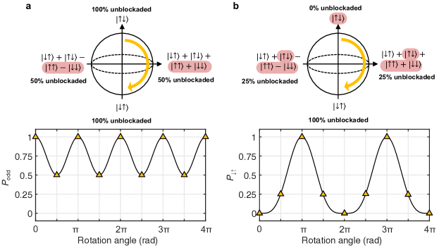
To make sense of the readout mechanisms, we discuss the Rabi oscillations observed when both qubits have the same Larmor frequency at the control point. In Supplementary Fig. 1, an initial state is left to evolve on resonance with a driving field, rotating the spins from to as shown by the Bloch spheres. Below the Bloch spheres are the projections of the states into (a) the parity readout basis and (b) the ST basis. In the parity basis, the probability of measuring a charge movement oscillates between 1 (either or ) and 0.5 (an equal mixture of , , , ). In the ST basis, the probability of measuring a charge movement starts at 0 since is blockaded, then evolves to an equal mixture of all four states, resulting in since only a quarter of the states are blockaded. When the evolution results in , the system is fully unblockaded, and . Therefore, adiabatic ST readout exhibits oscillations that decay to 0.75 , while with parity the oscillations decay to .
The ability to distinguish between and , i.e. adiabatic ST readout, is useful when observing SWAP operations. To measure SWAP oscillations with parity readout, and are no longer distinguishable, so an additional CNOT gate is needed before readout.
Adiabatic inversion exchange maps.
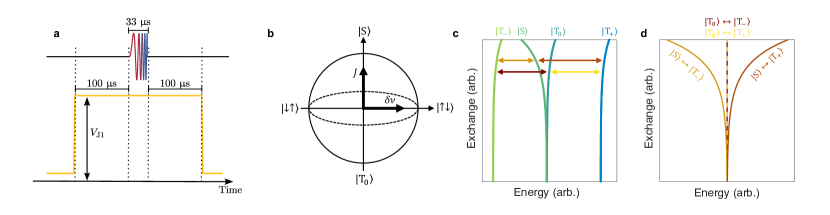
Fig. 1(d) shows a frequency scan of the qubit energies as a function of the gate voltage , which controls the exchange interaction. To achieve spin inversion, a chirped microwave pulse (i.e., an pulse whose frequency increases linearly in time) is applied to adiabatically drive spin transitions. The frequency chirp corresponds to a 650 kHz frequency shift over 33 µs.
The system is initialized in a state. However, after is ramped to the control point, there is a wait time of 100 µs before the adiabatic microwave chirped pulse is applied during which the qubits are left idle and undergo exchange oscillations [see Supplementary Fig. 2(a)]. In the case where is sufficiently high and exchange is large compared to the Larmor frequency difference , the initialized state undergoes SWAP oscillations. Consequently, at high the spin state before the adiabatic microwave chirped pulse becomes a 50/50 mixture of and or, equivalently, of and .
When the adiabatic microwave pulse is applied, we believe three types of transitions can be driven: a first branch that decreases exponentially in frequency corresponds to states transitioning into [light orange arrow in Supplementary Fig. 2(c)]; a second branch that increases exponentially in frequency corresponds to states transitioning into [dark orange arrow in Supplementary Fig. 2(c)]; finally, a third branch that remains constant in frequency in the middle of the map corresponds to states transitioning into and (see Supplementary Fig. 2(c-d) for the energy diagram corresponding to our model of this system). Due to the nature of the parity readout, only and will be blockaded, and any mixture of and will be unblockaded.
The branches corresponding to transitions are present. However, instead of the expected blockaded peak associated with transitions, we observe a central unblockaded peak in between two blockaded peaks. For Fig. 1(d) it is possible to explain this peak at high exchange in a similar fashion as in the case of low exchange interaction, where both spins are being resonantly driven via a multi-photon process and () turns into (), maintaining the even parity. When the microwave frequency is slightly off-resonant, partial adiabatic inversion is achieved, leading to a proportion of the spins being in an even state and resulting in the side fringes. Although it can be phenomenologically explained for Fig. 1(d), the absence of a central branch cannot be explained for Fig. 1(c) at , therefore it does not match our theoretical model and evidences our incomplete understanding of the dynamics of degenerate spins in a condition of high exchange.
Noise robustness simulations. During the exchange pulse there is a slight Stark shift from gate J1 that affects the two-qubit system – consistent with Extended data Fig. 2. The Stark shift will affect any qubit state that is perpendicular to this shift, meaning that any state that is not or will be perturbed by the Stark shift. This is seen in Fig. 2(d). For the case of no microwave drive and , the qubits are not affected by the Stark shift when exchange is on – confirmed by the coherent SWAP oscillation in Fig. 2(d). However, when the state before the exchange is switched on is which is affected by Stark shift. Fig. 2(g) shows a line cut of from (d). The Stark shift has the effect of bringing the qubit system out of sync with the rotating frame frequency, causing beating – consistent with the revival of the SWAP oscillations after 1s. Tuning the device to remove the Stark shift is needed to remove this beating.
For the case of the driven system with a continuous microwave, when in Fig. 2(e) there is no beating seen. This demonstrates robustness against shifts in the Larmor frequencies. There is a slight reduction in the SWAP oscillation visibility for longer SWAP times when comparing to , demonstrating some sensitivity to offsets in the Larmor frequencies. Further robustness is seen when the system is driven by the sinusoidal modulated microwave. Comparing the SWAP oscillations in Fig. 2(f) to , the visibility remains constant.
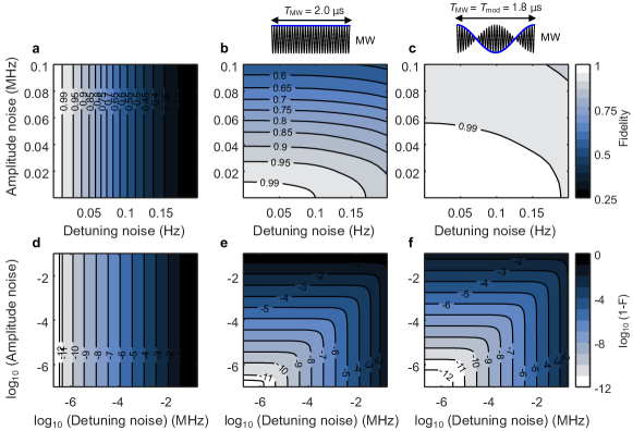
To confirm that this observation matches our theoretical interpretation, we simulated the SWAP oscillations for and , shown in Supplementary Fig. 3. The simulation follows the Hamiltonian in Eq. 1, and includes quasi-static Gaussian noise on the amplitude of the Rabi frequency and the Larmor frequency. On top of this, a Stark shift is implemented when the exchange is switched on. The simulation in Supplementary Fig. 3(d) shows a revival in the SWAP oscillation for the undriven system when , and no effect when . This is consistent with the experimental data, other than the overall visibility of the SWAP oscillations being affected by more general white noise, or 1/f noise. Both the continuously driven cases were also simulated with the same offsets in Supplementary Fig. 3(b) and (c) for and (e) and in (f). Both simulations confirm that neither of the driven cases are strongly affected by the Stark shift. Other noise sources would need to be introduced in the model to further improve the match of the simulation to the experiment.
To demonstrate the improvement in noise robustness for on-resonance driven SWAPs we also simulate the operator fidelity with detuning and microwave noise according to Ref. Hansen2021, in Supplementary Fig. 4. Again, we assume quasi-static Gaussian noise. The operator fidelity for the case with no microwave driving, Supplementary Fig. 4(a) and (d), shows that the SWAP operation is highly sensitive to detuning noise compared to the driven cases in (b,c) and (e,f). This agrees with our interpretation of Fig. 2(d-f).