Software-Defined Virtual Synchronous Condenser
Abstract
Synchronous condensers (SCs) play important roles in integrating wind energy into relatively weak power grids. However, the design of SCs usually depends on specific application requirements and may not be adaptive enough to the frequently-changing grid conditions caused by the transition from conventional to renewable power generation. This paper devises a software-defined virtual synchronous condenser (SDViSC) method to address the challenges. Our contributions are fourfold: 1) design of a virtual synchronous condenser (ViSC) to enable full converter wind turbines to provide built-in SC functionalities; 2) engineering SDViSCs to transfer hardware-based ViSC controllers into software services, where a Tustin transformation-based software-defined control algorithm guarantees accurate tracking of fast dynamics under limited communication bandwidth; 3) a software-defined networking-enhanced SDViSC communication scheme to allow enhanced communication reliability and reduced communication bandwidth occupation; and 4) Prototype of SDViSC on our real-time, cyber-in-the-loop digital twin of large-wind-farm in an RTDS environment. Extensive test results validate the excellent performance of SDViSC to support reliable and resilient operations of wind farms under various physical and cyber conditions.
Index Terms:
Wind farms, virtual synchronous condenser, software-defined control, software-defined networkingI Introduction
Offshore wind energy has been increasingly integrated into power grids. For instance, the State of New York has set the goal of integrating 9 GW offshore wind by 2035 to help build 100% electricity grids powered by zero-emission resources [1, 2, 3]. Large scale integration of offshore wind energy poses challenges to the operation of weakened power grid [4, 5, 6].
One effective approach to support large-scale integration of offshore wind energy is to use synchronous condensers (SCs), which can provide inertia [7], frequency regulation support [8], short-circuit current contribution [9], and sub/super-synchronous oscillations suppression [10] to the grid. However, conventional SCs are synchronous machines and their designs (e.g., locations and capacities) highly depend on the application scenarios [11, 12]. Correspondingly, the deployment and upgrade of SCs are highly expensive and they are unable to adapt to the frequently-changing grid conditions [9].
The overarching goal of this paper is to originate a lightweight, cost-effective, and adaptive approach to achieve the SC functionalities for wind energy integration. On the one hand, at the wind turbine and wind farm level, inverter controllers can provide built-in capabilities to realize various control functionalities, such as hierarchical control, synthetic inertia and instability damping [13]. Intuitively, if the inverter controllers are properly designed, they will be able to provide the desired SC functionalities while avoiding deploying the real synchronous machine hardware. On the other hand, software-defined control (SDC) [14], a recently emerging technology, also provides insights into resolving the hardware dependence issue. SDC virtualizes traditionally hardware-dependent inverter controllers into software-defined services and, in this way, realizes ultra-flexible and cost-effective controllers for power grids with significantly enhanced programmability and deployability.
In summary, this paper develops a software-defined virtual synchronous condenser (SDViSC), which realizes the SC functions without requiring the deployment of real SCs and hardware-dependent controllers. The main contributions are:
-
•
Architecture of virtual synchronous condenser (ViSC): We enable a built-in capability of wind turbines to provide programmable SC functions such as flexible Var capability, inertia, oscillation damping, and weak grid enhancement.
-
•
Engineering SDViSC: We accomplish SDViSC by devising a Tustin transformation-based SDC algorithm to virtualize the hardware ViSC controller as a software service, which enables capturing the fast dynamics of ViSC under limited communication bandwidth.
-
•
Resilient SDViSC communication by SDN: We further establish software-defined networking (SDN)-enabled communication for SDViSC to enable reliable operations of SDViSCs with low delays and high robustness even under communication network impairments.
-
•
Validated Prototype of SDViSC: A cyber-in-the-loop large-wind-farm prototype with 50 wind turbines is built in an RTDS environment, and extensive test results validate the superior programmability and flexibility of SDViSC and its capability to enable reliable operations of wind farms under weak grid conditions and cyber failures.
The remainder of this paper is organized as follows. Section II presents the design of ViSC and SDViSC. Section III develops the SDN-enhanced SDViSC. Section IV presents the established digital twin of SDViSC and provides extensive experiments to validate the performance of SDViSC. Section V concludes the paper.
II SDViSC for Wind Energy Integration
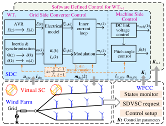
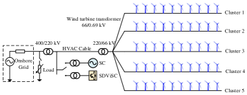
This section devises SDViSC, a software-defined virtual synchronous condenser, as seen Fig. 1, to support wind energy integration in an unprecedentedly programmable, adaptative and lightweight manner. In this paper, ViSC refers to SC functionalities provided by inverters with controllers implemented on specific hardware, such as DSP or PLC; SDViSC means that SC functionalities are provided by inverters with pure software-based controllers.
II-A Architecture of ViSC
We first design ViSC, which leverages wind generator converters to achieve the following control functions of SCs: i) to provide a natural inertial response and a short-circuit current, and ii) to generate or absorb reactive power to support voltage regulation. The design of ViSC includes control strategies for both grid-side and machine-side converters.
II-A1 Grid-Side Control
Our design of the grid-side converter adopts a double-loop control, as shown in Fig. 2.
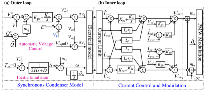
The outer-loop control is designed to achieve the following functionalities (see Fig. 2(a)): i) a mechanical model to provide inertia emulation and synchronization with the grid; ii) a voltage controller to provide the automatic voltage regulation (AVR) as conventional SCs, where an electrical model represents the stator windings; and iii) a supplementary controller customized to provide auxiliary control functions.
For the inertia emulation part, the transfer function to generate the phase angle is formulated as:
| (1) |
where , and are the Laplace transforms of the phase angle , injected torque error =- ( due to no input mechanical power), and the reference angular frequency , respectively; and are the emulated inertia constant and the damping factor of the ViSC, respectively.
For the AVR part, its transfer function is formulated as:
| (2) |
where and are the PI parameters of AVR; and is the droop coefficient; , , , , and are the AVR output, output voltage, output reactive power and the corresponding references, respectively; is the output of the supplementary controller, which will be discussed in (4).
The internally-induced voltage of the AVR block (i.e., ) is further connected with an electrical module to represent the electrical behavior of a synchronous machine. A commonly-adopted quasi-stationary electrical model is applied [15]:
| (3) |
where and represent the dynamic impedance; and are the virtual resistance and inductance; is the angular frequency of ViSC. A circular current limiter [16] is applied to limit the amplitude and preserve the angle of the output of the electrical model . The output of the current limiter, i.e., , provides the current reference for the inner-loop controller.
For the supplementary control block, in this paper, we design the following virtual friction control function to help ViSC suppress power oscillations and improve the frequency stability under weak grid conditions:
| (4) |
where , , , and , are the controller’s time constants and gains; the input signal is the frequency deviation , is the Laplace transform of ; the output signal is then sent to the AVR block as shown in (2). Eq. (4) adopts two control signals, i.e., the frequency deviation and the rate of change of frequency, to damp the power oscillation. A lead-lag controller to adjust the output magnitude is also used to further help oscillation suppression due to its better trade-off between static accuracy and stability.
The inner loop of the grid-side converter, as detailed in Fig. 2(b), includes a decoupled PI controller, a voltage feed-forward controller and an additional active damping controller, which improves the output current quality and suppresses filter voltage oscillations.
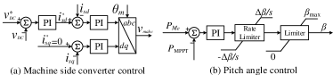
II-A2 Machine-Side Control
As for the machine-side control, our main target is to maintain a constant DC link voltage regardless of variations in the wind turbine machine speed and torque. This is achieved by the machine-side converter control and the pitch angle control, as shown in Fig. 3.
For the machine-side converter control (see Fig. 3(a)), the DC link voltage difference is regulated by a PI controller to generate the stator -axis current reference . The stator -axis current reference is set as 0, because the active power generated by the machine can be expressed as [17], where is the stator magnetic flux linkage. The pitch angle control (see Fig. 3(b)) is used to match the power consumed by the machine to maintain constant DC link voltage. The difference between and the captured wind power using maximum power point tracking (MPPT) is sent to a PI controller and the reference pitch angle is obtained through the pitch angle control framework [18].
Consequently, through ViSC, wind turbines can provide inertia support and voltage regulation as conventional SCs. Moreover, it provides programmable control performance to some extent, because the inertia constant and damping factor in corresponding control blocks can be flexibly adjusted.
II-B SDViSC: Software-Defined ViSC
Further, we discuss how to engineer an SDViSC, i.e., realizing ViSC in edge computing to fully release the virtualization and programmability advantages. The key to the development is a Tustin transformation-based SDC approach.
The basic philosophy of SDC is to achieve hardware-dependent control functions in a software manner by discretizing all continuous-time controllers into discrete-time ones [14]. During the SDC discretization procedure, conventional numerical integrators, such as Euler and trapezoidal methods, usually require small sampling rates to track fast dynamics to perform real-time control [19, 14], which unavoidably increases communication burdens from the SDC unit to WTs (see Section III), e.g., large communication bandwidth consumption.
To bridge the gap, this subsection devises a Tustin transformation-based SDC algorithm to realize SDViSC under fast dynamics and limited communication bandwidth.
II-B1 Tustin Transformation
The Tustin transformation is essentially a Taylor expansion-based “ to ” mapping of =, as shown below:
| (5) |
where is the sampling period. Using only the first term, the Tustin transformation is defined as follows:
| (6) |
The Tustin transformation preserves the properties of stability and the minimum phase of the original continuous-time controllers [20]. Thus, the original controllers’ performance can be guaranteed after discretization without requiring tiny sampling rates as required by conventional integration rules [14].
Next, we discretize ViSC using the Tustin transformation.
II-B2 Discretization of the AVR Block
PI controllers are the main-body of the AVR block. Given an arbitrary PI controller with the input , output and parameters and , the Tustin transformation can be performed as:
| (7) |
where and are the transforms of and . The PI controller output can be calculated recursively as:
| (8) |
Consequently, the output voltage of the AVR controller is calculated by the following rule:
| (9) |
Compared with SDC using conventional numerical integration rules, a notable feature of the Tustin transformation-based SDC is that (8) does not involve the cumulative control error. For example, the trapezoidal rule-based method [14] leads to a discretization of the PI controller as follows:
| (10) |
For each time step, (10) needs to compute the cumulative control error (), whereas (8) has no such requirements.
As a result, the devised Tustin transformation-based SDC can ensure that the control performance is unaffected by historical errors and therefore provides improved numerical stability. In other words, the Tustin transformation-based SDC can eliminate the steady-state error even using moderate sampling rates, which significantly reduces the communication burden.
II-B3 Discretization of the Inertia Emulation Block
This subsection derives the discretization rule of the outputs (i.e., phase angle and angular frequency ) of the inertia emulation block. Substituting (6) into (1) yields the following:
| (11) |
where denotes the transform of . Normalize the constant term in the denominator of the transfer function in (11) to 1, and after rearrangement and let , we have:
| (12) |
Consequently, the discretized recursive equation of is
| (13) |
Then, can be readily obtained from the derivative of :
| (14) |
Other control blocks, such as the inner-loop controller, supplementary controllers, can also be discretized using the same procedure to conduct the software-based implementation. Due to page limitations, details are omitted here. Finally, SDViSC is constructed by integrating all the discretized control blocks.
II-C Programmable Management of SDViSCs for Wind Farm Operations
Up to this point, we have achieved SDViSC for an individual wind turbine. Further, in a wind farm, wind turbines equipped with SDViSC can operate in parallel to increase the available ViSC capacity. This subsection discusses the management of multiple SDViSCs to assist wind farm-level operations.
Because of the utilization of SDC, each wind turbine equipped with SDViSC can flexibly switch its operating mode between the ViSC mode and various grid-following/grid-forming modes (e.g., control, control, droop control). The wind farm control center (WFCC) manages the software-defined operations of wind turbines:
-
•
Once a wind turbine is required to operate at the ViSC mode, the WFCC sends out control commands to the SDC unit to initialize the SDViSC, which includes the operating mode switching command, the programmable parameters of the ViSC (e.g., emulated inertia and damping factor), and the supplementary control functions to be applied.
-
•
Then, the SDC unit runs the discretized controllers (detailed in Subsection II-B) based on measurements received at each sampling time and outputs the control signals (e.g., signals for generating SPWM and adjusting pitch angle) to the destination wind turbine to perform the ViSC control.
-
•
Additionally, the SDC unit can also generate backup controllers to provide control redundancy and better robustness. The backup controllers will immediately pop up once there is a failure in the master controllers.
In summary, with SDViSC, the SC functionalities become one type of built-in services that wind turbines can provide. SDViSC enables two types of programmability that can not be achieved by traditional hardware-based SCs or ViSCs: i) all the control parameters can be programmed much more efficiently than hardware-inverter-based ViSC benefiting from the full softwarization; ii) the overall capability for providing the ViSC functionalities can also be flexibly programmed by switching the operating modes of wind turbines via SDC. Such programmabilities, without restrictions of hardware dependence, make SDViSC very adaptive to changing operating conditions and cost-effective for deployment and upgrading.
III SDN-Enhanced SDViSC Management for Large-Scale Wind Energy Integration
Since SDViSC management involves frequent communications between WFCC, wind turbines and the SDC unit, a dependable communication network is indispensable for guaranteeing the reliable operations of SDViSCs. This section establishes a software-defined networking (SDN)-enabled communication scheme for SDViSC management, which allows for ultra-reliable communication with low delays or congestion and hence supports resilient operations of large wind farms with hundreds or even thousands of wind turbines.
III-A Communication Activities in SDViSC Management
In the SDViSC management procedure detailed in Subsection II-C, three major communication activities are involved:
-
•
Monitoring: For each wind turbine, its connection status (i.e., connected or exited) and the operation mode (i.e., ViSC mode or other modes) are continuously monitored and sent to the WFCC for event detection and decision making.
-
•
Measurements: Once the ViSC mode is enabled for a specific wind turbine, measurements of this wind turbine, including the three-phase output voltages and currents, are sent to the SDC unit to implement the SDViSC control.
-
•
SDC/WFCC commands: The SDC unit sends out the control signals (e.g., the modulation signals) to specific wind turbines. The WFCC may also send control commands, such as voltage references, to adjust the operation of SDViSCs.
Traditional communication networks cannot fulfill SDViSCs’ data transmission requirements (i.e., low latency and high reliability) because of insufficient visibility to support real-time network monitoring and imprompt reactions to dynamic network conditions (e.g., congestion and link failure). SDN offers new insights into developing ultra-resilient, scalable and automatically configurable communication by separating the control/data planes and exploiting network virtualization technologies [21]. It enables direct control and management of communication networks through various functions, such as dynamic routing and traffic prioritization, and allows deploying new applications at a faster rate [22].
Inspired by the SDN philosophy, we perform SDViSC communications through an SDN-based communication network.
III-B SDN-Enhanced SDViSC Management
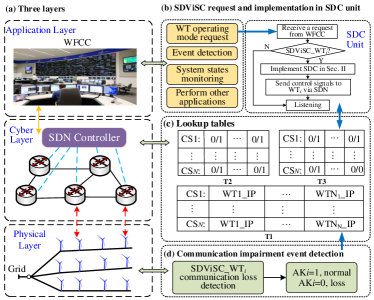
The three-layered SDN-enhanced SDViSC architecture is illustrated in Fig. 4: 1) a physical layer containing wind turbines in wind farms, 2) a cyber layer where the SDN controller manages the communication network for SDViSCs, and 3) an application layer for implementing SDViSC as well as other grid-forming/grid-following controllers.
III-B1 Design of SDN Functions
According to the communication activities involved in SDViSC management, the SDN controller is designed to provide the following functions.
First, the SDN controller monitors the status of the cyber-physical system and dynamically updates the related information, including the connection status and operating modes of wind turbines, requests from WFCC, etc. Here, we design three lookup tables to store the monitored information (see details in Subsection III-B2): 1) the IP address table (T1), 2) the wind turbine’s operating status and mode table (T2), and 3) the communication state table (T3). With those tables, the SDN controller can establish communication links as needed.
Second, the SDN controller manages the cyber system to ensure reliable and resilient communication to support SDViSC operations. For example, it can build communication links between the SDC unit and wind turbines as needed according to the information stored in T1, T2 and T3. It can also provide dynamic routing under network impairments, such as loss of communication. Here, we will design an event-based communication scheme to reduce communication burdens (see details in Subsection III-B3).
III-B2 SDViSC Network Monitoring
Typically, a large wind farm is divided into clusters, each consists of a group of wind turbines connected in series. We use the cluster (CS) number and the wind turbine number for indexing to design the lookup tables to store the communication network information.
Using the IP protocol, each wind turbine has a unique IP address stored in T1 and retrieved by the SDN controller. T1 is updated when changes occur in the physical layer (e.g., plug-and-play of wind turbines) or in the communication configuration (e.g., adding, deleting, or modifying IP addresses).
T2 stores wind turbines’ operating modes using three two-digit numbers for each wind turbine: ‘0/0’, ‘0/1’, and ‘1/1’. The first digit indicates the current operating mode, where ‘1’ represents the ViSC mode and ‘0’ are other modes. The second digit indicates whether the ViSC function is enabled, where ‘0’ means disabled (i.e., the wind turbine cannot work in the ViSC mode) and ‘1’ means enabled (i.e., the wind turbine can choose to work in the ViSC mode). Definitely, only when the ViSC mode is enabled, the current operating mode can be 1.
T3 stores wind turbines’ communication states also using three two-digit numbers: ‘0/0’, ‘0/1’, and ‘1/1’. The first digit represents the current communication state between a wind turbine and the SDC unit, where ‘1’ means the communication is on and ‘0’ means off. The second digit indicates whether there exists a link satisfying the communication requirement, where ‘1’ means yes and ‘0’ means no.
III-B3 Event-Based Communication for SDViSC Management
To reduce the communication bandwidth, we develop an event-based SDN communication scheme for SDViSC management so that communication is only required under specific events.
The following discusses two typical events: 1) , where the SDN controller receives a request to operate the -th wind turbine in the SDViSC mode; 2) , where dynamic routing is required for the -th wind turbine under communication impairments.
During wind farm operations, the SDN controller continuously listens to requests from WFCC. Once an event is triggered, the SDN controller sends a command to the SDC unit and retrieves the IP address of the destination wind turbine from T1. Then, T2 and T3 are successively checked to confirm that the ViSC function is enabled and the corresponding communication state is on. Finally, the SDN controller creates flow tables for SDN switches to build communication links between the destination wind turbine and the SDC unit so that the SDViSC control specified in Subsection II-C can be readily performed.
Under communication impairments, the dynamic routing event will be triggered to switch to a new communication path to guarantee reliable data transmission. Although the SDN controller provides a built-in function to periodically detect the network status, its performance is limited by the detection period and thus may not respond timely. Therefore, to ensure fast dynamic routing, we define an acknowledge signal to detect the network performance. If the -th wind turbine receives packets from the SDC unit normally, is 1; otherwise, it changes to 0. Then, is sent back to the SDN controller to check whether the dynamic routing should trigger by . A delay with 0.04 is added to the detection of based on the delay effect analysis in [14]. The added delay ensures that false detection will not be induced because the communication delay of Ethernet switches is much smaller.
In summary, the SDN-enhanced SDViSC management offers three benefits unattainable by traditional communication techniques: 1) it can effectively manage the network configurations and perform dynamic routing under communication failures, which enables great flexibility, reliability and resilience for the communication between SDViSCs, the WFCC and the SDC unit; 2) it adopts an event-based scheme, which avoids occupation of controller-to-switch bandwidth and reduces unnecessary data transmission; and 3) SDN benefits communications in complex networks by breaking communication barriers arising from proprietary protocols. This is because SDN directly controls the flow of data packets by creating the flow tables for routers among subnetworks, and adjusts data priority and throughput to avoid congestion. As such, SDViSCs’ deployment and management are not constrained by specific communication infrastructures and protocols.
IV Experimental Results
In this section, we thoroughly evaluate SDViSC’s performance on a real-time and hardware-in-loop prototype using RTDS. First, we validate the Tustin transformation-based SDC algorithm. Second, the performance of the SDViSC in comparison to the traditional SC is presented. Third, we validate the control efficacy of SDViSC to support reliable and resilient operations of wind farms under various conditions. Last, we demonstrate the reliability and benefits of the SDN-enhanced communication scheme for SDViSC management.
IV-A Testing Environment Setup
IV-A1 Test System
Fig. 5 shows our designed 500 MW offshore wind farm (OWF) test system with 50 PMSG based wind turbines111The designed OWF is extended from the CIGRE C4.49 benchmark system, which has two equivalent wind turbines with aggregated models [13]. to verify SDViSC. The 50 wind turbines are grouped into 5 clusters and integrated into the onshore power grid through a high-voltage alternating current (HVAC) cable. For comparison studies, a 40 MVAR traditional SC (referred to [7]) and an SDViSC with the same capacity by aggregating four wind turbines [13] are connected to the onshore point of coupling separately. Detailed designs are as follows:
-
•
Wind turbine controller: Wind turbines originally adopt a grid-following-based double loop control. Detailed control topology and controller parameters are provided in [13].
-
•
Onshore grid: It is modeled as an ideal voltage source connecting an impedance in series. The short-circuit ratio (SCR) can be adjusted to emulate different grid conditions [13] to provide a thorough evaluation of SDViSC.
IV-A2 Real-Time Prototype
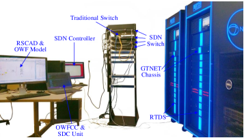
As depicted in Fig. 6, the SDViSC prototype has an OWF control center (OWFCC), an SDC unit, an SDN controller, four SDN switches, a traditional switch (L2 switch), GTNET2 cards, RTDS hardware, and the power system simulation software RSCAD that interacts with the RTDS hardware. Detailed settings are as follows:
-
•
Real-time OWF simulation: The OWF system (see Fig. 5) is developed and compiled in RSCAD. Two RTDS racks with 10 cores are utilized to simulate the OWF in real time.
-
•
Communication setup: GTNET2 cards are utilized for RTDS hardware to communicate with external devices, such as the OWFCC and the SDC unit, over a LAN/WAN. The GTNET2 cards provide Gigabit Ethernet ports for IP-based communications. UDP is used to transmit packets.
-
•
SDN setup: A real SDN network with an SDN controller and four SDN switches running OpenFlow protocols are used to manage the communication network.
IV-B Numerical Stability of the Devised SDC Algorithm
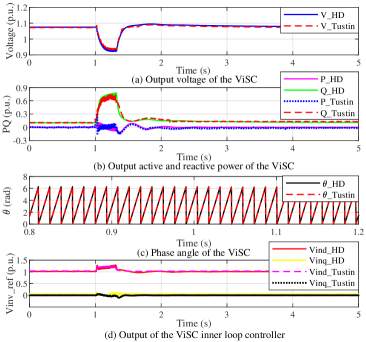
This part verifies the numerical stability of our designed Tustin transformation-based SDC algorithm and demonstrates its superiority over the trapezoidal rule-based SDC algorithm [14]. ViSCs directly implemented in RSCAD emulate the performance of hardware-dependent controllers and serve as the ground truth for evaluating the performance of software-defined controllers. A phase-to-ground fault is studied, which occurs at the grid side at 1s and is cleared at 1.3s.
IV-B1 Performance of Hardware-Dependent ViSC
The solid lines in Fig. 7 illustrate the responses of hardware-dependent ViSCs. Fig. 7 (a) and (b) show that when the fault occurs, ViSCs immediately generate reactive power to support the grid voltage and successfully bring the system back to normal operation after the fault clearance. The phase angle in Fig. 7(c) from the inertial emulation block and the voltage reference in Fig. 7(d) for inner-loop modulation also demonstrate ViSCs function well as designed, i.e., providing inertia response and reactive power support as SCs do.
IV-B2 Performance of SDViSC based on Tustin Transformation
The dash lines in Fig. 7 illustrate the performance of SDViSC using the Tustin transformation-based SDC algorithm. A moderate sampling rate, i.e., 0.67ms, is adopted. Simulation shows SDViSC performs as well as the hardware-dependent ViSC, and there is almost no obvious performance deterioration. Therefore, our method can facilitate fast and low-cost deployment of SC functionalities with qualified control performance.
In contrast, Fig. 8 presents the performance of the trapezoidal rule-based SDC algorithm [14] under a sampling rate 0.25 ms (i.e., the smallest sampling rate that can be realized under the communication bandwidth setting). It can be seen that the system collapses at around 2.2s, which indicates the trapezoidal-based SDC fails to provide the designed control functionality under limited communication bandwidth because of the accumulated historical error (as discussed in Subsection II-B2). Although further decreasing the sampling rate can improve the performance of trapezoidal-based SDC, it will unavoidably bring higher requirements on communication and increased vulnerability against network impairments.
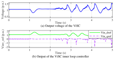
As a conclusion, the Tustin transformation-based SDC ensures enhanced numerical stability compared over existing methods, evidenced by the fact that a much larger sampling rate (lower communication requirement) can be adopted without affecting the control performance.
IV-C Comparison between the SDViSC and Traditional SC
This subsection compares their performance from four aspects: voltage regulation capability, inertia support, short-circuit capacity contribution and grid strength enhancement.
IV-C1 Voltage Regulation Capability
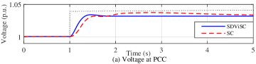
Fig. 9 (a) presents the voltage regulation performance when changing the voltage references for the AVRs of the traditional SC and SDViSC from 1.0 p.u. to 1.04 p.u. at 1s separately. It can be seen that: 1) both the SC and SDViSC boost the voltage around 1.035 p.u. finally; 2) SDViSC offers faster regulation speed and thus improved voltage regulation capability than the traditional SC.
Fig. 9 (b) shows the SDViSC’s voltage stiffness characteristics, the inner potential’s ability to tolerate the difference between the real and reference reactive power over a time interval. It is determined by , the reciprocal of the integrator parameter of AVR’s PI controller [23]. The grid voltage decreases by 0.08 p.u at 1 s, it can be observed that: 1) with a larger , the changing rate of voltage at the onshore point of coupling is reduced; 2) the static deviation of voltage is not improved; and 3) the voltage nadir is pulled up and enhanced. This kind of stiffness characteristic provided by the SDViSC is beneficial to improve the voltage dynamics.
.
IV-C2 Inertia Support
As shown in Fig. 3, the machine side converter is controlled to inject current to the DC link capacitor to maintain a constant voltage during the inertia support process. Therefore, the energy stored in the capacitor (determined by capacitance value) and extracted from the machine side impacts the performance of SDViSC. Here two load-increasing cases are performed:
-
•
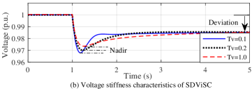
i) Load increases by 50 MW: Fig. 10 (a) illustrates the inertia support performance when the SDViSC and traditional SC have the same inertia constant (i.e., H=3s). The system frequency decreases as the load increases and the frequency nadir is almost the same for the SDViSC and SC. Fig. 10 (b) and (c) further present the advantage of the programmability of SDViSC in comparison to SCs. The frequency nadir is decreased when increasing the inertia of SDViSC, which clearly shows its advantage to adapt to the evolution of the grid’s needs. The decreased oscillation frequency also indicates enhanced system performance.
-
•
ii) Load increases by 100 MW: Fig. 11 (a) demonstrates the system responses with the SDViSC and traditional SC of the same capacity and inertia constant. It can be seen that the system experiences a larger frequency dip with the SDViSC than that with SC because of the limited stored energy by wind turbines. Fig. 11 (b) presents the frequency responses when paralleling a 2000 Ah Li-ion battery with the DC capacitor. The obviously decreased frequency nadir indicates improved inertia support in comparison with the case having no storage.
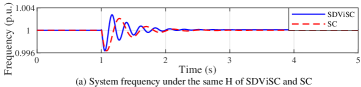
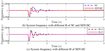
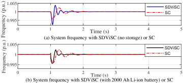
As a conclusion, equivalent inertia support as traditional SCs can be offered by the SDViSC when having adequate stored energy [24]. It is also worth highlighting that the inertia constant of SDViSC can be programmed to satisfy the system’s evolving needs. Guaranteeing a solid inertia support service similar to traditional SCs, additional storage equipment is required to be installed or operating multiple WTs as SDViSCs in parallel, which will be validated in subsection IV-D.
IV-C3 Short-Circuit Capacity Contribution
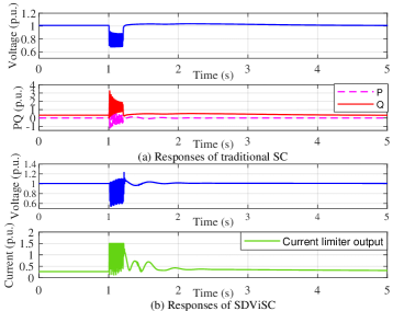
The maximum peak current is set to be 1.5 p.u. [25]. Fig. 12 presents the outputs of the SDViSC and the traditional SC under a single-phase to ground fault, which starts at 1 s and is cleared at 1.2 s. It can be observed from the results that:
-
•
Both the SDViSC and the traditional SC instantaneously inject reactive power to boost the voltage.
-
•
As shown in Fig. 12 (a), the SC offers a short-circuit current that rises to 4 p.u. and the residual voltage is above 0.7 p.u..
-
•
The SDViSC’s contribution is directly limited by its overcurrent capability, as shown in Fig. 12 (b). The residual voltage is about 0.6 p.u., which is lower than that of the SC. Therefore, an SDViSC with a larger capacity is required to provide comparable short-circuit current as the SC does.
IV-C4 Grid Strength Enhancement
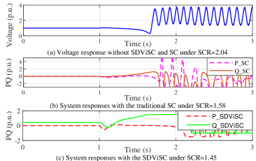
We compare the capability to suppress instability under weak grid conditions via three cases: 1) without SDViSC or SC, 2) with only SC and 3) with only SDViSC. Fig. 13 presents the results that the studied case is becoming unstable under the largest SCR (the boundary value for system stability and instability). It can be seen that:
-
•
When there is no SC or SDViSC, the system is unstable (see Fig. 13 (a)) when the SCR decreases to 2.04, the voltage oscillates severely and deviates largely from the rated value.
- •
-
•
With SDViSC, the system can be stabilized under further lower SCR (see Fig. 13 (c)). Thus, the grid-forming control based SDViSC with changeable parameters performs better than SCs to maintain stability under changing conditions.
In summary, the following observations can be obtained:
-
•
The SDViSC outperforms the SC in terms of voltage regulation speed and its voltage stiffness characteristics are beneficial to system voltage dynamics.
-
•
With adequate stored energy, SDViSC can provide equivalent inertia support as the SC, alternative ways are installing extra storage equipment or operating multiple WTs as SDViSCs in parallel to reduce the effects of hardware limitation. Its parameters can be flexibly reconfigured to adapt to changing grid conditions.
-
•
The overcurrent capability of converters, which is definitely below the capability of SC, limits their short-circuit capacity contribution. Quantification for specific converters may be needed before deployment to provide the same contribution.
-
•
The SDViSC with programmable parameters performs better given enough capacity than the SC to maintain transient stability under weak grid conditions.
IV-D Control Efficacy of SDViSC
We verify SDViSC’s control efficacy under three scenarios, including plug-and-play of SDViSCs, parallel operation of SDViSCs and oscillation damping under weak grid conditions.
IV-D1 Plug-and-Play of SDViSCs
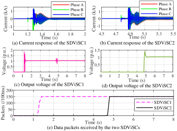
In this part, we demonstrate how the OWF reacts under the plug-and-play operation of SDViSCs. Specifically, two wind turbines in Cluster 1 and Cluster 4 are plugged into the OWF as SDViSCs at 1.2 s and 4.8 s, respectively. Fig. 14 presents the physical and cyber states of these two SDViSCs before and after the plug operation. It can be observed from the results that:
-
•
When SDViSCs are connected to the OWF, the software-defined controllers immediately start to operate the wind turbines as ViSCs to provide voltage and inertia support.
-
•
As shown in Fig. 14(a)-(d), currents and voltages of SDViSCs can be stabilized in a short time (i.e., within around 0.1s) after the plug operation, which indicates a satisfactory transient performance of the designed ViSC control.
-
•
Communication is only required when the wind turbine is operating as a ViSC. Fig. 14 (e) presents the packets received by the two SDViSCs, which clearly show that the SDN controller builds the communication link in a timely manner after receiving a request from the OWFCC.
IV-D2 Parallel Operation of SDViSCs for Voltage Regulation
A single SDViSC may not be able to provide the functionalities of a large-capacity SC. Therefore, we propose to operate multiple SDViSCs in parallel to increase the overall capacity.
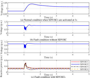
First, we demonstrate the efficacy of the parallel operation of SDViSCs for providing voltage regulation services. The leftmost 4 wind turbines in Cluster 3 operate in parallel as SDViSCs with voltage droop coefficients of 0.03, 0.05, 0.07, and 0.1. Results are shown in Fig. 15:
-
•
Fig. 15 (a) first studies the performance of SDViSCs in normal operating conditions (i.e., without any faults). It can be seen that before the deployment of SDViSC (before 1s), the PCC voltage is 0.97 p.u., which is below the rated voltage. After SDViSCs are activated to inject reactive power, the PCC voltage is accordingly boosted to 1.02 p.u..
-
•
Fig. 15 (b)-(c) further study the system responses under a phase-to-ground fault that occurred at the grid side at 1s. Fig. 15 (b) shows that without SDViSCs, the PCC voltage drops to 0.4 p.u. after the fault. However, as shown in Fig. 15 (c), when SDViSCs are deployed, the PCC voltage during and after the fault can be significantly improved. The reason is that SDViSCs perform reactive power sharing according to their voltage droop coefficients to support the grid voltages.
In summary, simulation results indicate that SDViSCs are competent to provide voltage regulation functionality as traditional SCs under both normal operating and fault conditions.
IV-D3 Parallel Operation of SDViSCs for Improving the Transient Stability of Weak Grids
Further, we demonstrate the capability of SDViSCs to improve the system’s transient stability under weak grid conditions. At time , the SCR is changed from 7.14 to 1.51 by adjusting the impedance of the onshore grid to simulate weak grid conditions.
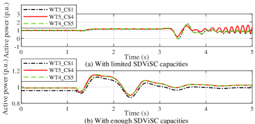
In comparison to the scenario without SDViSCs shown in Fig. 13 (a), Fig. 16 compares the system performance with 3 SDViSCs (i.e., limited ViSC capacities) and 4 SDViSCs (i.e., enough ViSC capacities). It can be observed that:
-
•
With 3 wind turbines operating as SDViSCs, Fig. 16 (a) shows that SDViSCs indeed enhance the system’s transient stability compared with Fig. 13 (a), and hence this weak grid can maintain stable until 3s. However, because of the limited capacity of SDViSCs, the system still deviates from the nominal operating point after 3s and finally loses stability.
-
•
Further, with 4 SDViSCs, Fig. 16 (b) shows that the oscillations can be damped and the system can finally achieve a stable operating condition.
In summary, the ability of SDViSCs to improve transient stability can be flexibly programmed by switching the operating modes of wind turbines and changing the number of available ViSC controllers. Therefore, SDViSCs can adaptably satisfy the system needs under changing grid conditions, which outperforms traditional SCs with nonadjustable capacity.
IV-E Communication Resilience of SDViSC
This subsection demonstrates the communication resilience of the designed SDN-enhanced SDViSC management. Two typical cyber events are studied: 1) communication network impairment and 2) controller failover.
IV-E1 Network Impairment
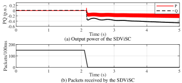
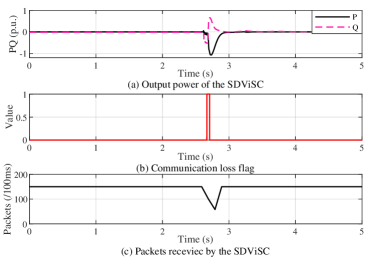
First, we study the performance of SDViSC under network impairments, which may occur frequently in real-world communication networks and can significantly affect the operation of SDViSCs. A physical failure of the communication link of wind turbine 1 in Cluster 1 is triggered to simulate bad network conditions. The testing results without and with the SDN-enabled communication are shown in Figs. 17 and 18, respectively. It can be observed that:
- •
- •
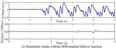
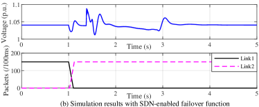
IV-E2 Controller Failover
One salient feature of the developed SDN-enhanced SDViSC is the controller failover function, which ensures during any controller failure, a backup controller can be conveniently implemented using software to provide redundancy and reliability for wind farm operations.
Fig. 19 provides the results with and without the SDN-enabled controller failover function carried out for wind turbine 1 in Cluster 1. It can be seen that:
-
•
When the SDN-enabled failover function is disabled, the performance of the SDViSC deteriorates severely after the controller malfunction, even though the cyber network is still working (see Fig. 19 (a)).
-
•
When the failover function is enabled, the backup controller immediately starts to work after the controller malfunction, and the SDN controller establishes a new communication link (see Fig. 19 (b)). The operation of SDViSC becomes normal after a short period of oscillations. The handover capability enabled by the SDN-based communication scheme ensures the stable functioning of SDViSC.
V Conclusion
In this paper, we devise SDViSC to operate full converter wind turbines as virtual SCs in an unprecedented programmable, adaptable and lightweight manner. A Tustin transformation-based SDC algorithm is developed to virtualize controllers with fast dynamics in SDViSC. An SDN-enabled communication scheme is further established for SDViSC management with great communication resilience and reduced communication burden. A real-time, cyber-in-the-loop prototype for a large wind farm is built to validate the efficacy of SDViSC in an RTDS environment. Extensive experimental results demonstrate that SDViSC can be operated flexibly to provide SC capabilities to support reliable and resilient offshore wind farm operations. Comparison results with SCs show that the hardware limitation can be reduced by using together with storage and enhanced power converters.
References
- [1] “Offshore Wind Power for New York,” https://sunrisewindny.com/, 2022.
- [2] M. V. Liu and et al, “An open source representation for the NYS electric grid to support power grid and market transition studies,” IEEE Trans. Power Syst., 2022.
- [3] W. Wan, P. Zhang, M. A. Bragin, and P. B. Luh, “Cooperative fault management for resilient integration of renewable energy,” Electr. Power Syst. Res., vol. 211, p. 108147, 2022.
- [4] H. Wu, X. Wang, and Ł. H. Kocewiak, “Impedance-based stability analysis of voltage-controlled mmcs feeding linear ac systems,” IEEE J. Emerg. Sel. Top. Power Electron., vol. 8, no. 4, pp. 4060–4074, 2019.
- [5] M. K. Bakhshizadeh and et al, “Improving the impedance-based stability criterion by using the vector fitting method,” IEEE Trans. Energy Convers., vol. 33, no. 4, pp. 1739–1747, 2018.
- [6] C. Li, S. Wang, F. Colas, and J. Liang, “Dominant instability mechanism of vsi connecting to a very weak grid,” IEEE Trans. Power Syst., vol. 37, no. 1, pp. 828–831, 2022.
- [7] H. T. Nguyen, G. Yang, A. H. Nielsen, and P. H. Jensen, “Combination of synchronous condenser and synthetic inertia for frequency stability enhancement in low-inertia systems,” IEEE Trans. Sustain. Energy., vol. 10, no. 3, pp. 997–1005, 2019.
- [8] H. T. Nguyen and et al, “Applying synchronous condenser for damping provision in converter-dominated power system,” J. Modern Power Syst. Clean Ener., vol. 9, no. 3, pp. 639–647, 2020.
- [9] J. Jia and et al, “Impact of VSC control strategies and incorporation of synchronous condensers on distance protection under unbalanced faults,” IEEE Trans. Ind. Electron., vol. 66, no. 2, pp. 1108–1118, 2018.
- [10] Y. Wang, L. Wang, and Q. Jiang, “Impact of synchronous condenser on sub/super-synchronous oscillations in wind farms,” IEEE Trans. Power Deliv., vol. 36, no. 4, pp. 2075–2084, 2020.
- [11] H. T. Nguyen, M. N. Chleirigh, and G. Yang, “A technical & economic evaluation of inertial response from wind generators and synchronous condensers,” IEEE Access, vol. 9, pp. 7183–7192, 2021.
- [12] L. Bao and et al, “Wind farms in weak grids stability enhancement: SynCon or STATCOM?” Electr. Power Syst. Res., vol. 202, 2022.
- [13] L. Kocewiak and et al, “Overview status and outline of stability analysis in converter-based power systems,” in Proc. Virtual Wind Integr. Workshop, 2020, p. 10.
- [14] L. Wang, Y. Qin, Z. Tang, and P. Zhang, “Software-defined microgrid control: The genesis of decoupled cyber-physical microgrids,” IEEE Open Access J. power energy, vol. 7, pp. 173–182, 2020.
- [15] O. Mo, S. D’Arco, and J. A. Suul, “Evaluation of virtual synchronous machines with dynamic or quasi-stationary machine models,” IEEE Trans. Industr. Electron., vol. 64, no. 7, pp. 5952–5962, 2017.
- [16] M. G. Taul and et al, “Current limiting control with enhanced dynamics of grid-forming converters during fault conditions,” IEEE J. Emerg. Sel. Top. Power Electron., vol. 8, no. 2, pp. 1062–1073, 2019.
- [17] M. Chinchilla and et al, “Control of permanent-magnet generators applied to variable-speed wind-energy systems connected to the grid,” IEEE Trans. Energy Convers., vol. 21, no. 1, pp. 130–135, 2006.
- [18] X. Lyu, J. Zhao, Y. Jia, Z. Xu, and K. P. Wong, “Coordinated control strategies of PMSG-based wind turbine for smoothing power fluctuations,” IEEE Trans. Power Syst., vol. 34, no. 1, pp. 391–401, 2019.
- [19] R. Zhao and et al, “A novel discretization method for multiple second-order generalized integrators,” IEEE Trans. Power Electron., vol. 36, no. 10, pp. 10 998–11 002, 2021.
- [20] M. Al-Alaoui, “Novel approach to analog-to-digital transforms,” IEEE Trans. Circuits Syst. I: Regul. Pap., vol. 54, no. 2, pp. 338–350, 2007.
- [21] P. Zhang, B. Wang, P. B. Luh, L. Ren, and Y. Qin, “Enabling resilient microgrid through ultra-fast programmable network,” Dec. 10, 2019, US Patent 10,505,853.
- [22] P. Zhang, Networked microgrids. Cambridge University Press, 2021.
- [23] L. Shang and et al, “VSC–based voltage stiffness compensator to improve grid voltage dynamics,” Front. Energy Res., p. 3, 2022.
- [24] T. Ding and et al, “Two-stage chance-constrained stochastic thermal unit commitment for optimal provision of virtual inertia in wind-storage systems,” IEEE Trans. Power Syst., vol. 36, no. 4, pp. 3520–3530, 2021.
- [25] D. Lepour and et al, “Performance assessment of synchronous condensers vs voltage source converters providing grid-forming functions,” in 2021 IEEE Madrid PowerTech. IEEE, 2021, pp. 1–6.