The HIBEAM program: search for neutron oscillations at the ESS
Abstract
With the construction of the European Spallation Source, a remarkable opportunity has emerged to conduct high sensitivity searches for neutron oscillations, including a first search for thirty years for free neutrons converting to antineutrons. Furthermore, searches can be made for transitions of neutrons and antineutrons to sterile neutron states. Upgrades to the ESS infrastructure allow an improved HIBEAM design that would provide an increase in sensitivity of an order of magnitude compared to previous work.
The HIBEAM program corresponds to baryon number violation by one and two units. The observation of a process satisfying a Sakharov condition addresses the open question of the origin of the matter-antimatter asymmetry in the Universe. Sterile neutron states would belong to a ‘dark’ sector of particles which may explain dark matter. As electrically neutral, meta-stable objects that can be copiously produced and studied, neutrons represent an attractive portal to a ‘dark’ sector.
This paper describes the capability, design, infrastructure, and potential of the HIBEAM program. This includes a dedicated beamline, neutron optical system, magnetic shielding and control, and detectors for neutrons and antineutrons.
1 Introduction
The European Spallation Source (ESS) will become the most powerful research facility worldwide for neutron-based studies once it reaches full completion [1]. With its exceptional capabilities, including a higher useful flux of neutrons compared to any existing research reactor and an unprecedented level of neutron brightness, the ESS surpasses current neutron sources.
The ESS is presently in the process of constructing 15 instruments as part of its comprehensive suite, consisting of 22 instruments necessary to fully achieve its scientific objectives as defined in the ESS statutes [2]. Furthermore, the ESS has a dedicated mandate for fundamental physics research. However, one of the critical missing elements is the absence of a dedicated beamline specifically designed for fundamental physics experiments [3] . This identified limitation highlights the importance of establishing such a beamline to fulfill the ESS’s comprehensive scientific mission. In this context, taking advantage of the ESS scientific capability the HIBEAM (High-Intensity Baryon Extraction and Measurement) collaboration aims to conduct a program of beam neutron oscillation searches. Upgrades to the ESS infrastructure allow an improved HIBEAM design with respect to earlier work [4, 5].
The goals of the HIBEAM project are outlined in Ref. [4]. In this paper, a design is given of a HIBEAM beamline with which a number of high precision searches for neutron oscillations can be made. Neutrons converting to anti-neutrons and/or sterile neutrons are high precision probes of baryon number violation (BNV) and address a number of open questions in modern physics, including baryogenesis and dark matter.
For the first time in over thirty years, a competitive search for free neutrons converting to anti-neutrons will be made. The HIBEAM sensitivity exceeds that of the previous search at the ILL [6] by around an order of magnitude. The improvements are due to the capability of the ESS source, and improvements in neutron focusing and detector technology since the last search. Similar sensitivity improvements are expected for the HIBEAM program of searches for sterile neutrons compared to earlier searches made at ultra-cold neutron (UCN) facilities [7, 8, 9, 10, 11, 12, 13, 14].
This paper is organised as follows. A brief motivation for neutron conversion is given. This is followed by an overview of the phenomenology of neutron conversions which is used to explain the principles underpinning the design of the search program. The ESS and HIBEAM beamline are then described. This is followed by a description of the magnetic shielding and control infrastructure, after which the neutron and antineutron detectors are described.
2 Motivation for neutron oscillations
The observation of neutron conversions to anti-neutrons and/or sterile neutrons at HIBEAM would be of fundamental significance. The HIBEAM program corresponds to ‘essential scientific activities’ in 2020 Update to the European Particle Physics Strategy [15]. The HIBEAM searches exploit unique BNV channels for which, unlike single proton decay in which and must be simultaneously violated to conserve angular momentum, is the only hitherto conserved quantity which is violated. Furthermore, owing to the experimental challenges of performing such searches there are comparatively few searches for free neutron-antineutron conversions compared with, for example, the leptonic equivalent process of neutrinoless double beta decay .
While the need for ‘blue sky’ exploration and high-sensitivity testing of conservation laws strongly motivates the HIBEAM program, there also exists a number of theoretical arguments, summarised below, outlining why BNV is expected. Furthermore, as discussed, neutron conversions can arise as a single phenomena addressing a specific problem, eg baryogenesis, as well as being coupled to other signals of new physics such as neutrinoless double beta decay.
- 1.
-
2.
The conservation of corresponds, like , to an accidental symmetry in the SM. For theories extending the SM, BNV and lepton number violation (LNV) therefore tend to occur generically. For example, observable low-scale BNV via neutron conversions features in extensions of the SM, such as scenarios of extra dimensions [22], branes [23], and supersymmetry [24, 25, 26].
-
3.
Sterile neutrons can belong to a dark/hidden sector of particles which interact gravitationally and not via the gauge forces of the SM [27, 28, 29, 30]. Such a sector can provide an explanation for Dark Matter. As meta-stable and electrically uncharged objects which can be copiously produced and studied, neutrons offer an attractive portal to a dark sector.
-
4.
There exists a symbiosis between neutron-antineutron conversions and other key observables for new physics sought by the community. The conversion of a neutron to antineutron (, ) is the baryonic equivalent of neutrinoless double beta decay (, ). Both processes feature in unification scenarios and theories of neutrino masses [31, 20, 21, 32]. Furthermore, neutron-antineutron conversion, neutrinoless double decay and single proton decay are coupled via the electroweak sphaleron interaction, the existence of which is a fundamental prediction of the SM. The sphaleron process can be written as . This implies that, if any two of the following processes are observed, then the other should exist: transition (the first six quark operator), proton decay (the second 4-fermion operator) and =2, lepton number violation. The last term implies a low energy process such as neutrinoless double beta decay.
3 Phenomenology of the neutron conversions and search principles
HIBEAM is a unique facility that can probe the full range of neutron mixing possibilities between antineutrons and sterile states [33, 34]. The Hamiltonian for neutrons in a -field is given in Equation 1.
| (1) |
The terms , and are the Majorana mass mixing parameter, and mass mixing parameters for and for , respectively424242A more general expression for the Hamiltonian allows for the possibility of a transition magnetic moment (TMM) [35]. This is not included here though a search for a TMM can be performed with HIBEAM.. In a minimal approach, the neutron mass () and magnetic moment () are assumed to the same as that in the sterile sector. The magnetic moments for particle and anti-particle are opposite for both the visible and sterile sectors. Magnetic fields, and exist in the visible and sterile sectors, respectively.
Many different possible processes are possible. Equation 2 gives the process probabilities as a function of propagation time , in the quasi-free regime, for free neutrons to antineutrons (). Probabilities are also given for sterile neutron processes434343These processes can involve sterile neutrons and sterile antineutrons. For simplicity, only the sterile neutron mode is written here. Physical limits and sensitivities are not dependent on this simplification. In the event of a discovery, the ability to perform a range of searches, including neutron-antineutron transitions via sterile states, helps pin down the various contributions from sterile neutrons and sterile antineutrons.: neutron-antineutron transformation (), neutron regeneration () and neutron disappearance (). The characteristic oscillation times for each process ()are the reciprocal of each of the amplitudes. The terms and denote the propagation times before after conversion.
| (2) |
There are several notable features of neutron conversion theory that guide the searches.
-
1.
The probability of observing a process in the quasi-free limit is enhanced by a power with increasing propagation time, motivating a long beamline and sample of slow neutrons. The discovery potential of a future experiment is often best quantified by an expression involving the propagation time raised to a power rather than the propagation time.
-
2.
Outside of the quasi-free limit, the above probabilities become massively suppressed. For free neutron-antineutron conversions, to achieve the quasi-free condition in a beam experiment requires nT [36]. For transitions to sterile neutron states, the magnetic fields in the visible () and sterile states () combine such that the transition probability has a resonant-like behaviour as the visible field is varied [37].
-
3.
A sterile magnetic field can be generated in a number of ways. For example by hypothetical ionization and flow of gravitationally captured dark material in and around the Earth [37]. Such an accumulation could occur due to ionized gas clouds of sterile atoms captured by the Earth e.g. due to photon–sterile photon kinetic mixing; present experimental and cosmological limits on such mixing [38] and geophysical limits [39] still allow the presence of a relevant amount of sterile material at the Earth for magnetic fields less than several gauss [40].
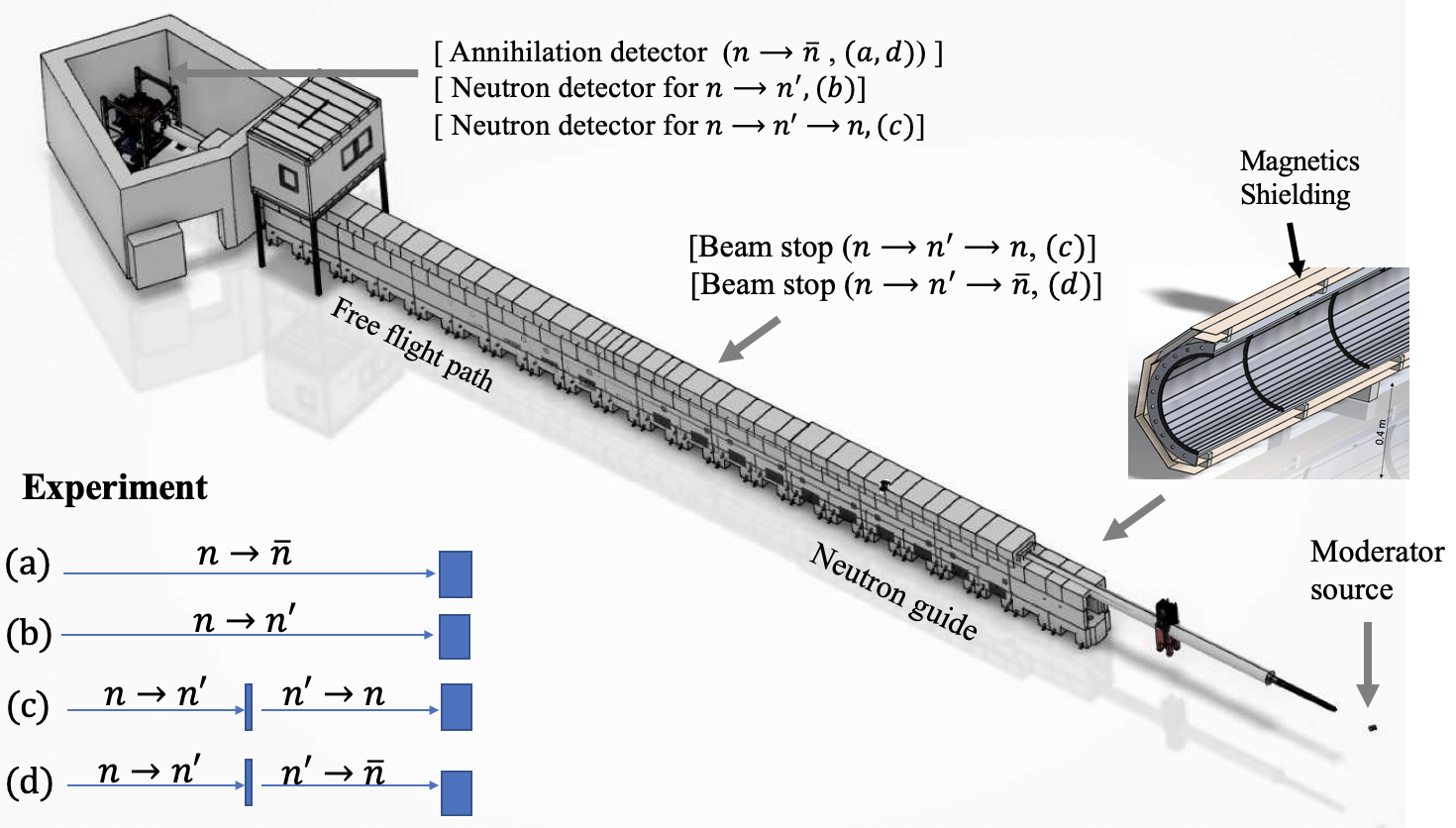
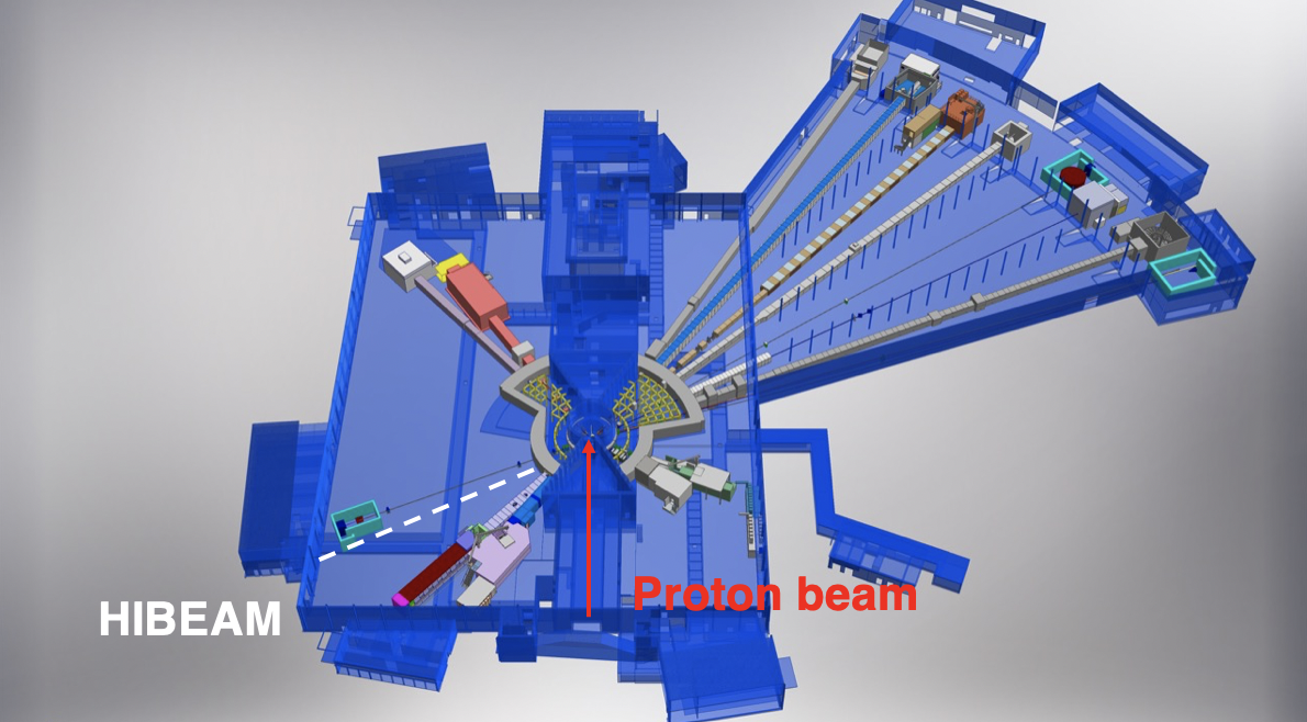
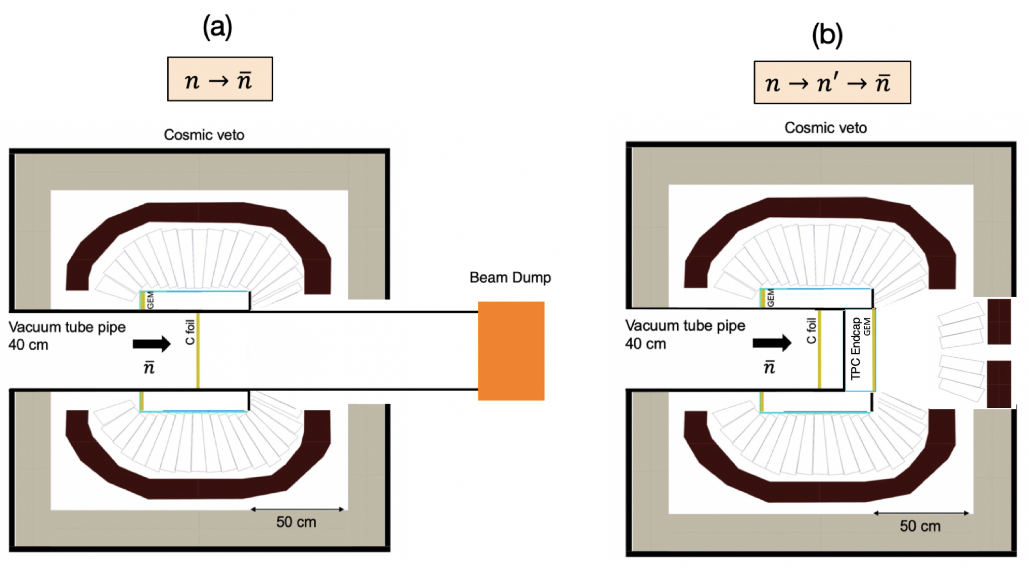
The principles of the neutron conversion searches are illustrated in Figure 1. The figure shows a CAD model of the HIBEAM beamline for a search for free neutrons to antineutrons (). More information of the various features of the CAD model given in Section 6 and subsequent sections. Neutrons are passed through a neutron guide into a free passage volume and eventually pass through a thin ( m) carbon target, surrounded by a detector. The detector would observe the products of the antineutron-nucleon annihilation.
The figure also illustrates how the beamline configuration changes for sterile neutron searches. Neutron-antineutron conversions via sterile neutrons () require a scan over different magnetic field values to reach the resonance regime. At an optimised magnetic field, a sterile state in one propagation volume is induced. The sterile neutron then passes through a beamstop which prevents the passage of neutrons. A magnetic field in a second propagation volume then induces the transition of the sterile neutron to an anti-neutron, the annihilation signature of which can then be observed.
A similar set-up can be used to observe sterile neutrons via the transition of sterile neutrons into neutrons rather than anti-neutrons following the beamstop. The process () provides a classic regeneration experiment. Sterile neutrons can also be potentially observed as an anomalous loss of neutrons at the end of a beamline ().
4 The European Spallation source
The ESS facility and how it relates to neutron oscillation projects is described in Refs. [4, 41]. It employs a linear accelerator to accelerate protons. The exceptional neutron flux achieved at ESS is a direct result of its possession of the world’s most powerful accelerator and the utilization of the highest beam power directed toward the target. The proton beam employed in this process follows a pulse structure of 14 Hz, with each pulse lasting 2.86 ms. Through acceleration, the proton beam reaches an energy of 2 GeV, powered by a current of 62.5 mA. The ESS is presently committed to delivering 2 MW power on target by 2028, with a final aim for a beam power of 5 MW.
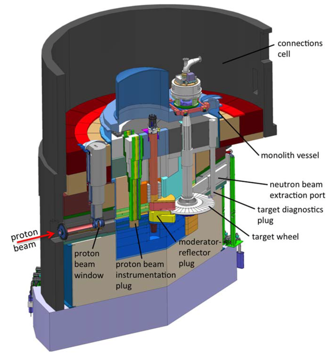
Once the proton beam reaches its ultimate energy, it collides with a rotating tungsten target, resulting in spallation and the production of primarily evaporation neutrons at around 2 MeV. The spallation neutrons undergo moderation within the neutron moderators contained within the moderator-reflector plug, as shown in Figure 3. Initially, the ESS will be equipped with only a single compact low-dimensional moderator located above the spallation target, which has been designed to deliver brightest neutron beams for condensed matter experiments [42]. The target and moderator-reflector system is located within a shielding configuration referred to as the monolith. Figures 2 and 3 illustrates the proton beam, the target, and the monolith structure.
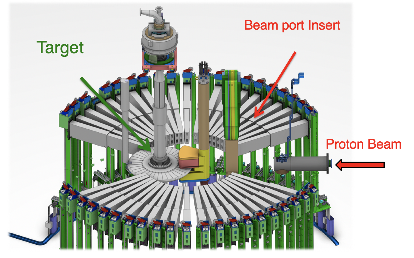
As shown in Figure 3, the ESS possesses a total of 42 beam ports. These beam ports play a crucial role in the facility as they serve as the neutron extraction systems, responsible for transporting neutrons from the target to the instrument area. Surrounding the monolith is another protective structure known as the bunker [43]. The bunker serves as a shielding area that envelops the ESS monolith, shielding the instrument area from the high levels of ionizing radiation generated during operation. The roof and walls of the ESS bunker are constructed out of heavy magnetite concrete. Within the bunker areas, the neutron beamlines are equipped with neutron guides and other instrument-specific equipment such as choppers or shutters.
5 The HIBEAM searches
The fundamental principles of the searches are shown in Figure 1. Further details on sensitivities are given here.
5.1 Search for free at the HIBEAM beamline
Previous searches for free oscillations were conducted at the Triga Mark II reactor [44, 45] and at the ILL [46, 47]. The ILL search [47] performed almost 30 years ago provided the most stringent limit for the free neutron oscillation time of about seconds. No new searches for free oscillations have been performed despite theoretical interest and several proposals to improve the experimental sensitivity. These experiments require both an intense neutron source and a team with diverse expertise in magnetic shielding, particle physics detectors, and slow neutron optics.
The experiment involves a focused beam of free neutrons propagating in a sufficiently field-free (or ”quasi-free”) region [33] towards a detector able to detect the antineutron annihilation. In this detector, any antineutrons would annihilate with a thin target (for this reason, we referred to it as the annihilation detector), resulting in a final state of charged pions and photons see Section 7.2. The figure of merit () of sensitivity for a free search is given by:
| (3) |
where is the number of neutrons per unit time reaching the annihilation detector after seconds of flight through a magnetically protected, quasi-free conditioned vacuum region. The probability of a conversion is therefore proportional to the number of neutrons times the squared transit time. A high precision search therefore requires a large flux of cold neutrons (i.e. neutrons with energy below 0.025 eV) which are allowed to propagate freely over a long time to allow conversions to antineutrons. These conditions are satisfied at the ESS.
Searches for can also be done with neutrons bound in nuclei. annihilation inside a nucleus would liberate pions and photons inside large-volume underground detectors [48, 49, 50, 51, 52, 53, 54, 55, 56, 57]. An analysis by Super-Kamiokande [56, 57, 58] infers a lower limit on the free neutron oscillation time of s. Atmospheric neutrinos and other backgrounds make it more difficult for underground detector searches to claim a discovery compared to a laboratory experiment such as HIBEAM, where one can manipulate the magnetic field to check any positive observation. The mean field estimates of the conversion rate may be enhanced or suppressed by nucleon-nucleon correlation effects [32] which are not yet fully understood. It is scientifically unwise to look for new phenomena in only one experimental channel: the diversity of approaches supported to discover neutrinoless double beta decay is a clear example. We conclude that both types of searches are needed, with free neutron searches being the cleanest from both theoretical and experimental perspectives.
5.2 Searches for sterile neutrons
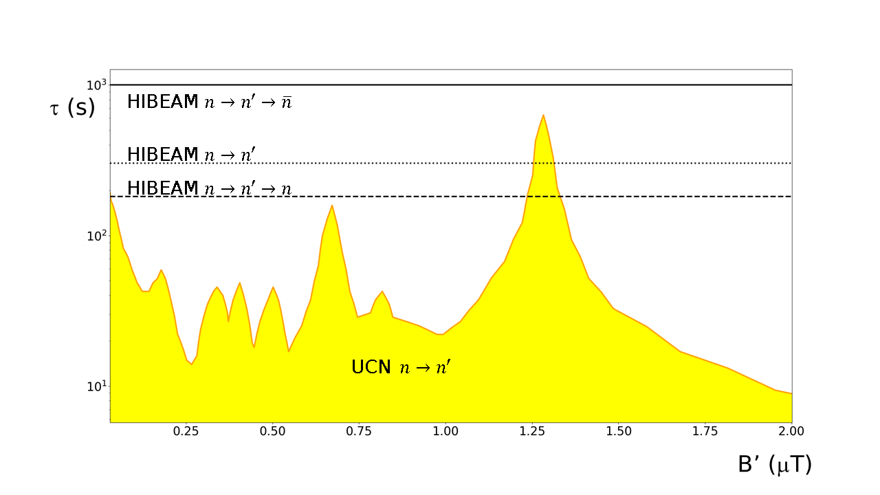
These search modes require scans over different magnetic field configurations. Following the procedure in [59], the sensitivity in oscillation times can be estimated for the HIBEAM beamline for magnetic fields scans in the up-down direction with step size 2 mG between G. Dedicated 3-D magnetic scans with high statistics are used to investigate signal candidates.
A sensitivity on up to 180 s for the neutron regeneration experiment with the ESS at 2 MW power can be achieved for a running period of around one ESS year for a magnetic field region up to 2 G and background rate of 0.1 neutron/second. For the disappearance mode, this increases to 300 s for a detector with 25% efficiency. These outstrip limits from UCN over a wide range of magnetic field and can achieve order-of-magnitude improvements.
The search for neutron-antineutron conversions via sterile neutrons provides a sensitivity on . Unlike the other searches, an effective background-free search can be achieved. This leads to a sensitivity on that exceeds s, the precise value depending on the smallness of the expected background. HIBEAM expects to run background-free i.e. with an expected number of background events following selections , as the ILL did. A sensitivity up to s is set as a benchmark. A comparison of HIBEAM sensitivities with limits from UCN experiments is given in Figure 4.
6 The HIBEAM beamline
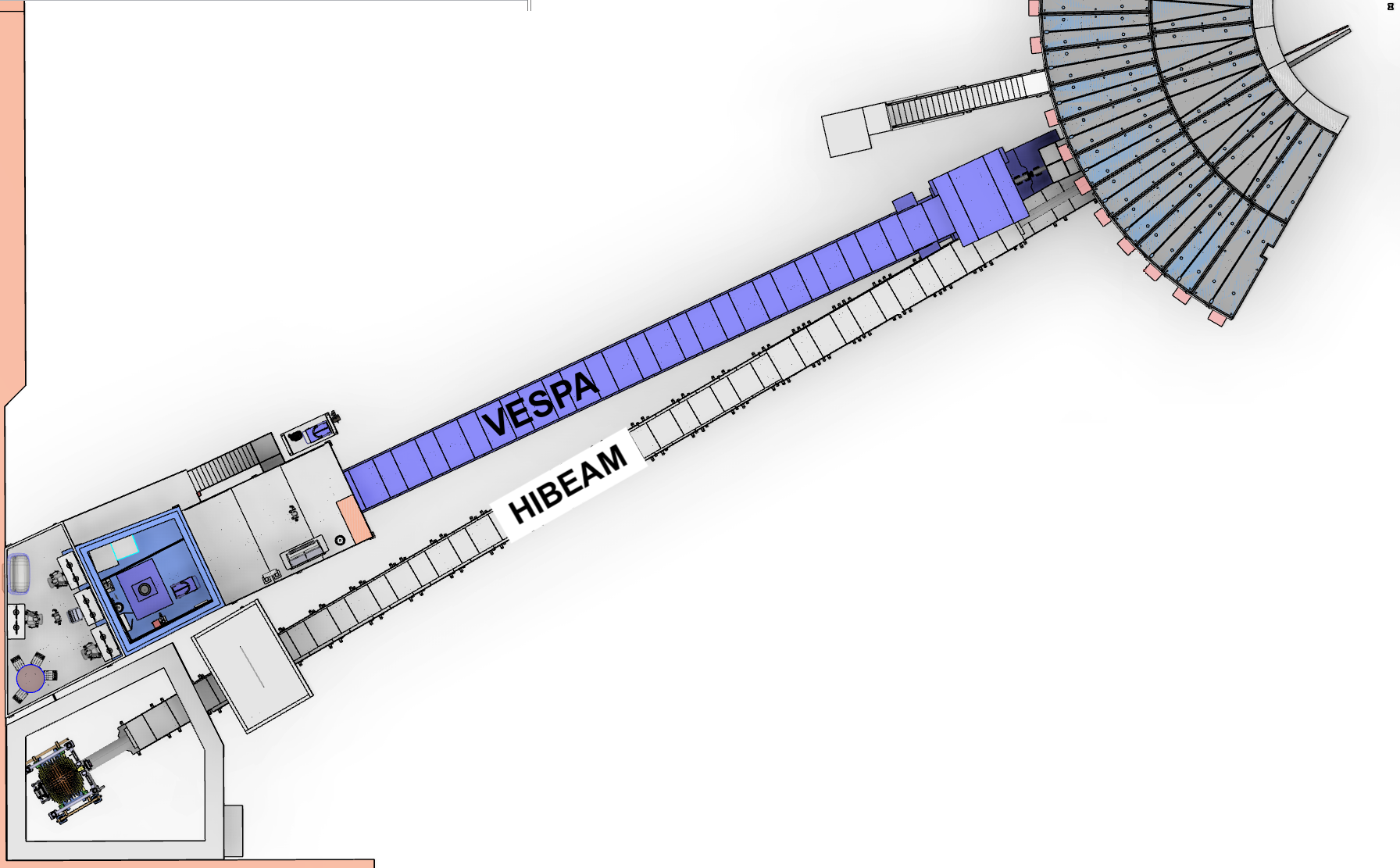
To conduct the searches, a world-leading neutron beamline capable of delivering the highest flux of free neutrons to the experimental area is essential. Currently, a neutron extraction system that could be used for the HIBEAM beamline is under construction. The extraction system will be located in the ESS East sector. Figure 5 shows the ESS instrument suite, including all the current instruments under construction. Figure 6 depicts the east sector. HIBEAM could be positioned at beam port E6, close to the VESPA instrument. The beamline will have a guide length of 65 m.
The layout of the HIBEAM beamline is shown in Figure 6. The neutron extraction system is situated within the ESS target monolith see Fig 2. The neutron extraction system plays a crucial role in transporting neutrons outside the target, and it will be positioned between 2 meters from the moderator up to 5.5 meters.
This system comprises two main components: the Neutron Beam Port Insert (NBPI) and the Neutron Beam Optics Assembly (NBOA), represented by the grey and yellow structures in Figure 7, respectively. For the NBOA we are assuming a copper substrate, but we can also consider aluminium or steel as established alternative technologies, depending on structural factors. The preferred option for the NBOA is an elleptical guide coated with an supermirror.
Following the extraction system, an additional 20-meter-long elliptical neutron guide is required to transport the neutrons to the experimental area. The elliptical guide is then followed by an extensive neutron flight region. Ultimately, the neutrons will enter the experimental area, where depending on which experiment will be carried out the neutron detector or the antineutron detector will be installed.

Regarding the second optics system shown in Figure 8, located between the ESS bunker and the guide shielding, simulations using the McStas [60] ray-tracing package have demonstrated that, with this system, it is possible to deliver n/s number of neutrons to the target, corresponding to the for the neutron to antineutron search of at 5MW operating power. This was calculated for the option with an annihilation target of a 40cm diameter, determined by the compact dimensions of the WASA calorimeter (see Section 7.2). A Much higher could be achieved for the option where the annihilation target has a size of 1m see Section 7.3. The elliptical guide is not the only option for the optics system located in the ESS bunker; nested mirror optics similar to the one used for the NNBAR system [61] are other possibilities. While the elliptical guide remains the current baseline, the other options are currently under study.
6.1 Magnetic Infrastructure
As described above, after passing through the second optics system, the neutrons will reach the magnetic control area. For the neutron to antineutron search, the magnetic field in this region needs to be 5 nT to ensure the free flight condition. This requirement imposes a technological challenge, however prototyping for an arbitrarily extendable length detachable low frequency shield has been pursued before [62].
Major challenges here are (i) extending the low magnetic field region to 60 m from typically few meters length of most existing magnetic shields; (ii) shielding in a constrained space and high radiation environment.
The free condition is fulfilled if the average magnetic field is below 5 nT. With a minimally particle velocity of 400 ms-1, the flight time in the low field region is 0.1625 s, corresponding to a characteristic frequency of 6.2 Hz. It is therefore necessary that the next to a static reduction of magnetic fields, also frequencies up to 10 Hz show an amplitude below 5 nT. To obtain a field-free (or quasi-free) region, a combination of re-direction of magnetic field lines and absorption of magnetic energy through Eddy currents is required, next to interruptions of the magnetic flux in the shield to shorten the impact of the magnetic fields of detector and spallation target.
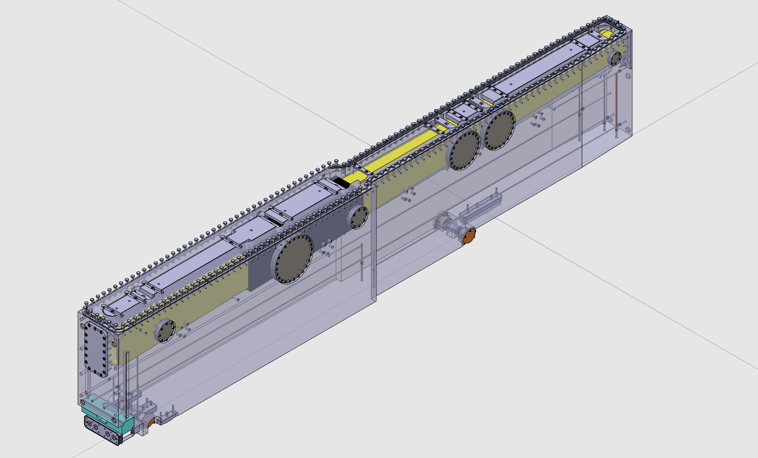
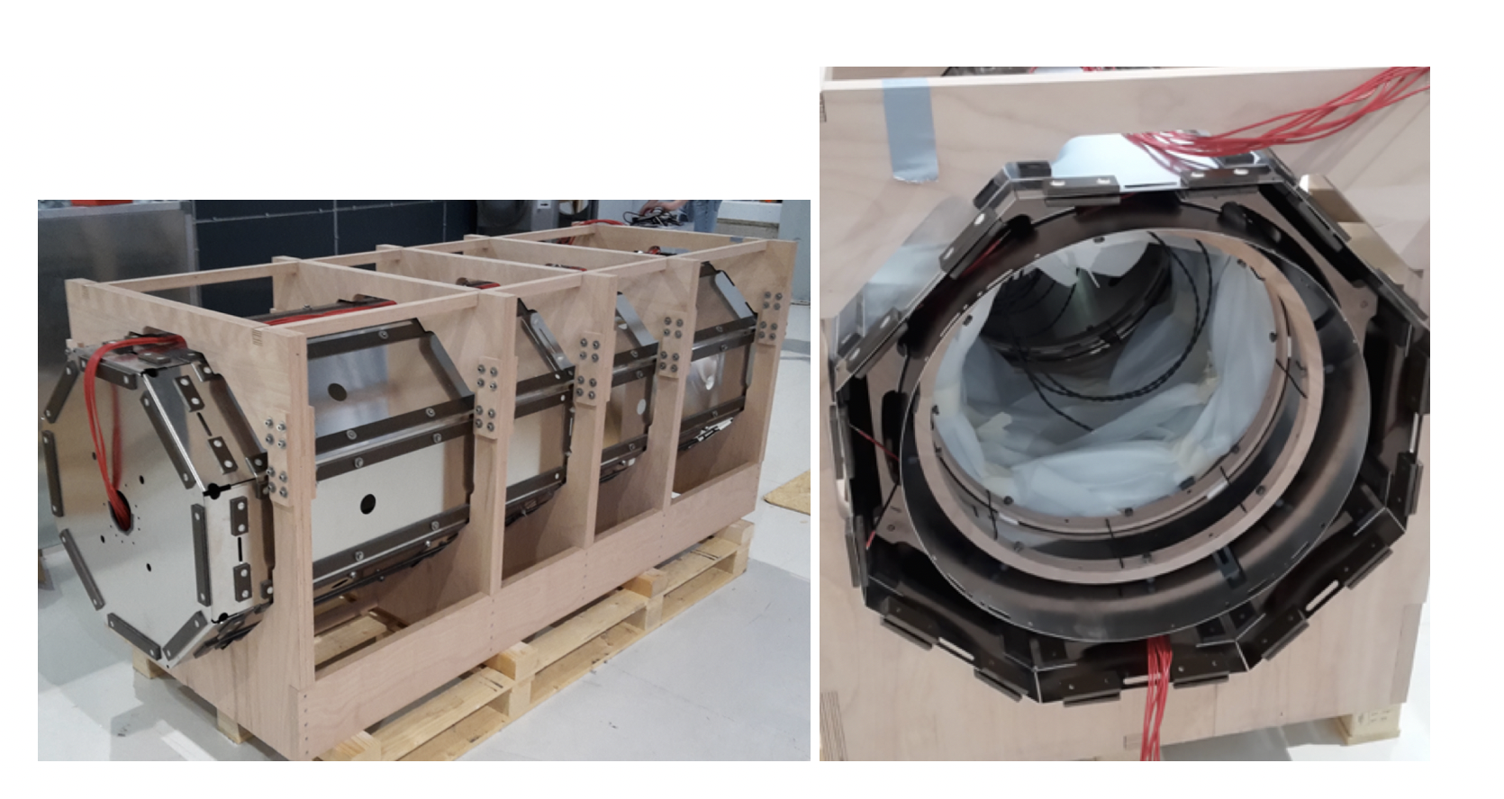
Figure 9 shows the concept, which includes the vacuum chamber made from aluminum, surrounded by a two-layered magnetic shield made from mumetal.
The aluminum vacuum chamber will have a thickness of 14 mm to withstand vacuum pressure and a diameter of 0.6 m, with high material purity to avoid neutron activation. Circling currents in the material shield external magnetic fields above 1 Hz. Access for vacuum equipment and instrumentation will be provided from the side, with 100 mm ID Alu tubes placed periodically at 2 m spacing, which connect after 40 cm distance to pumps, placed outside the magnetic shield. The branch tubes act as waveguides to prevent low frequency distortions from entering the inside volume, while providing sufficient vacuum conductivity to obtain 10-6 mbar inside.
The mumetal shields are composed of an octagonal assembly in two nested shells with an inner diameter of 0.6 m and 0.75 m, from 4 individual bent segments around the circumference of maximum 750 mm width and 300 mm length in axial direction. The segments overlap by 50 mm and can be assembled after the vacuum chamber is installed and provide flexible access for instrumentation of the beam line. To achieve a residual field of 5 nT within the whole volume of the vacuum chamber by reduction of remanent magnetization of the passive magnetic shield, magnetic equilibration needs to be carried out. With state of the art equilibration [63] by a sinusoidal current with linearly decreasing envelope over 20 s into a set of toroidal coils wound around the inner octagonal shield (also in independent sections of the shield), this goal is feasible (as demonstrated in [62]). To obtain optimal performance along the beam line, the enlarged diameter of the shield ensures that remanent fields close to the shield surface do not case more than 5 nT at the inside of the vacuum chamber. The shield will be mounted every 1.5 m with screws on detachable plastic frames, which separate the shields mechanically and electrically from the vacuum chamber and each other. Even with increased thickness of the shields in the middle third of the length to compensate for additional flux from the earth field. However, in the free flight region, the magnetic field requirement is only T, which is achieved by a separated mumetal ring-section placed to catch residual flux from the detector, while not guiding the flux into the shielded region. Also, for the vacuum chamber, additional constraints apply to the detection region with the annihilation target inside the vacuum chamber and the detector placed outside. Due to the geometry of the annihilation target and the extreme background requirement, the quality of the reconstruction of the reaction particles must be of very high quality. In turn, the material thickness of the chamber must be small to avoid angular broadening of the annihilation products passing the material due to Moliere scattering. For aluminum with 0.5 mm wall thickness, this effect is small enough to accommodate for the reconstruction precision required by the 100 m thick annihilation target, taken into account in the design of the vacuum chamber. Here, the chamber wall is milled down to the required thicknesses and deformed due to the vacuum pressure, with only thick strips of material left to match the structural stability requirements. The loss in shielding efficiency for 1-100 Hz due to the reduced material thickness does not extend more than 0.5 m into the shield. With the specific requirements for this setup, the experiment is also future technology demonstrator in the magnetic aspects: Ring-geometry for field reduction were specifically developed in preparation for this project, which enable the modularization of magnetic shields, easy access through shields for pumping and sensing, as well as minimization of large stray fields at the end of the shields; Thickness variations of the shield layers and the segmentation of the magnetic equilibration procedure was also specifically investigated and developed as preparation for this project. Magnetic equilibration is also done to ensure stability of applied magnetic fields inside the shield.
Regarding the sterile neutron searches where there is a need for applying magnetic fields coil systems to generate longitudinal and transverse magnetic fields will be installed. Transverse fields up to 300 T are generated with 2 sets of so-called cosine-theta coils with 90 rotated alignment with a homogeneity of ; a longitudinal field is generated with a loosely wound solenoid axially with the shield and vacuum chamber. Here, the homogeneity is improved by the shield, which forms a configuration known as “magic box” when used with lids and short aspect ratio, resulting also in close to relative homogeneity. Magnetic characterization of the shield is done using fluxgate magnetometers, which are moved through the shield on a trolley. Magnetic equilibration resets the field distribution and amplitude to typically within 1 nT after any arbitrary treatment in the shield, extrapolating from experience [62]. Online magnetic characterization is then optionally done using polarized neutrons similar to [64], where polarized neutrons and a spin echo method were used. Here, this approach could be advanced by deploying a small cell or removable polarizing optical components at the beginning of the shielded section to polarize neutrons at different positions in the beam. A 0.5 m long RF section operated at few 100 Hz at 10 T for flipping at the beginning of the beam line and a second one at the end could for example enable spatial online mapping while providing sensitivity to additional exotic physics cases.
7 Detectors
Both neutron and anti-neutron detectors are required for HIBEAM.
7.1 The neutron detector configuration
The very high instantaneous neutron rates in the neutron detectors needed for different experimental configurations in this work are far too high to count individual neutron pulses and one must use current mode detection. Since one cannot apply the usual types of signal discrimination in this case, one must be careful to ensure that the extra noise in the measured current from background processes and from fluctuations in the number of current-generating quanta from each individual neutron capture in the detector are both small compared to where is the number of neutrons. The burst of fast neutrons from the ESS target/moderator system is gone by the time the slow neutrons of interest arrive at the detector, so the most serious background for neutron detectors in the direct beam comes from gammas. It is therefore important for the detector to be able to withstand fast neutron bombardment with no ill effects and be insensitive to gammas. It should also incorporate a method to subtract the gamma-induced component of the neutron detector signal without using the usual method of pulse shape discrimination.
An ion chamber composed of 3He gas and using the He H MeV reaction provides a gamma-insensitive, fast neutron radiation-damage-insensitive medium with a high absorption cross section for slow neutrons and sufficient energy release to create enough ions per neutron capture that the detector noise can still closely approach the limit. The small fraction of the signal induced by background gammas in the beam in such a 3He ion chamber can be subtracted by placing an identical 4He ion chamber just in front of the 3He ion chamber. To an excellent approximation the induced signal in the 4He ion chamber comes only from the gammas in the beam, and a 3He ion chamber with the same dimensions and gas pressure directly behind the 4He ion chamber will possess a nearly identical response to gammas. Therefore one can subtract these two signals to leave only that from the neutrons. Szymanski et. al [66] successfully demonstrated this concept at the LANSCE pulsed spallation neutron source. Possible backgrounds from neutron activation of ion chamber components by high energy neutrons and gammas can be quantified at ESS using the signal from the fraction of the time-of-flight frame outside the slow neutron arrival time and also by taking data during dropped pulses from the ESS proton accelerator. Fast neutrons in the beam appear to early in the time-of-flight frame to be confused with the slow neutrons of interest for this work.
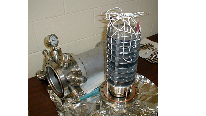
Addition of other species to the gas can reduce the range of the 3H and to a few mm for easily-achievable gas pressures. We used a helium-argon gas mixture in the segmented ion chamber we developed for polarized slow neutron spin rotation measurements of parity violation [65]. The Figure shows a picture of the detector used in this measurement. Segmentation of the detector ion collection plates can be arranged transverse to the beam both to allow for imaging and also to reject possible common-mode noise from pulse-to-pulse fluctuations in the beam phase space not caught by the low efficiency monitor upstream. The ion chamber detector can also be segmented along the beam direction to take advantage of the fact that the slower neutrons are more likely to be absorbed at the entrance to the chamber due to the behavior of the neutron absorption cross section. Ionization signals from different depths into the detector therefore gives information on the neutron energy spectrum. The comparison of this data with the neutron time-of-flight information enables a check of boundary effects in the ion chamber response from ions that are lost to the collection plates by absorption in materials.
The required precision and stability of the total charge measurement from the absorbed neutron beam should be for this work. A 3He-based neutron ion chamber of design similar to that described above was used in a recent neutron- parity violation experiment at SNS which reached precision [67]. This success bodes well for our ability to meet this specification. The stability of the efficiency of such an ion chamber can be quite high as it depends only on chamber geometry and stability of ion collection fields, constant gas composition and density, and electronics properties. The current mode signals are large enough that no electronics gain stage need be employed: one needs only a current to voltage convertor.
A detector with a variable efficiency as desired for this work can be realized by changing the 3He gas pressure. Clean metal bellows compressors which operate in the required pressure range and which are rated for the safe handling of tritium gas (a nontrivial amount of tritium gas is generated in the 3He ion chamber) are commercially available. Eventual safe extraction of the tritium gas at the end of the measurements can easily be done by exposing a hydrogen getter to the gas as was done in [67].
7.2 The annihilation detector
The signature of the neutron-antineutron transition is via the annihilation of an antineutron on a Carbon target surrounded by an annihilation detector (see Fig. 11). Such interactions produce a multipion state (3-5 charged pions and photons from neutral pion decays) with momenta between 100-300 MeV [68, 69, 70]. In order to detect such a signal a dedicated annihilation detector comprising tracking and calorimetry is needed. A schematic of the annihilation detector that will make use of the WASA experiments [71] calorimeter can be seen in Fig. 11. Incoming antineutrons traveling from the left in the vacuum tube annihilate in a thin Carbon foil. Energies of annihilation products are measured in the CsI(Na) calorimeter previously used in the WASA experiments [71] at CELSIUS in Uppsala, at COSY in Julich and presently at FAIR, Darmstadt. The WASA calorimeter is very compact, can be transported and will be available for the HIBEAM project after 2027. Charged particle track directions for event topology are measured in 3D by a cylindrical Time Projection Chambers (TPC). Particle identification is done with a combination of TPC and calorimeter.
Since the only energetic enough background that could make up an annihilation signal is cosmic rays, an active shield of scintillator bars will surround the experimental setup. Events coincident with a charged particle signal in the cosmic veto will be rejected. To avoid self inhibition, an absorber thick enough to stop all charged pions from the annihilation is needed between the calorimeter and the scintillators. Cosmic events made by neutral particles will be identified by missing vertex in the foil. The frequency of fake annihilation events due to cosmics (and other natural backgrounds) will be studied by shutting off the neutron flux at the neutron port.
The annihilation detector shall collect as much evidence as possible that a annihilation has occurred. The task is to detect and identify the final state particles, verify the energy and momentum balance to be compatible with annihilating at rest and to verify the event topology with a common vertex in the annihilation foil for all particles. Annihilation in a nucleus opens additional ways to dissipate energy and momentum by re-scattering in the nucleus.
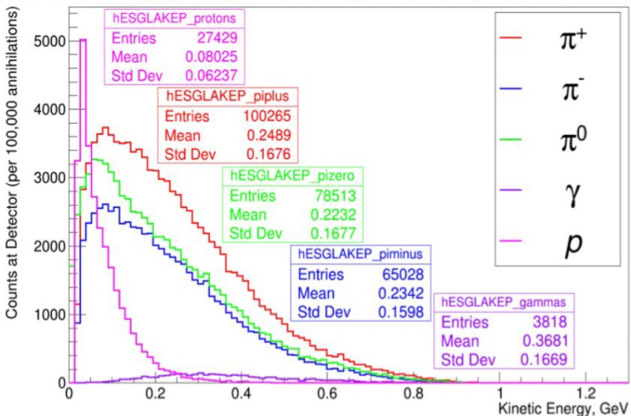
Figure 12 shows the simulated kinetic energy distributions of particles emitted when annihilation takes place in a carbon nucleus. Consequently the requirements on energy and momentum conservation cannot be as strict in the annihilation as in the free case, as long as not all particles can be detected (neutrons and nuclear remnant are missing) but it will anyway be in an energy regime where no natural sources can contribute than those of cosmic origin.
Around 91.5% of the annihilations give at least one . A good electromagnetic calorimeter which can trigger on is essential. Also at least 2 charged pions are present in 98.5% of the cases and in addition protons often come out from the nucleus. So charged particle tracking can reconstruct the event topology with a common vertex in the foil. Both tracking and calorimetry will have as large geometrical coverage as possible.
Figure 11 shows the detector for the mode for the and searches. The brown frame is a solid Iron construction in which the CsI(Na) modules are mechanically fixed by their light guides to Photo Multiplier (PM) tubes on the outside of the iron.
The two search modes and are quite different.
The traditional search for transformation based on degenerate states in the absence of external electromagnetic and strong (nuclear) fields will have a very low probability and must be searched for by observing a maximal number neutrons over as long flight time as possible. Instead, for the mode by scanning systematically over weak -fields a resonant behavior will enhance the production of which in turn transforms to . If the process exists, it should be governed by drastically higher probabilities at the proper resonance setting for the magnetic fields. One expects rates of annihilation events per hour compared to events one per month or even year in the traditional case.
An important difference between the two cases is that in the standard search the neutrons beam will fly through the annihilation target therefore the neutron induced nuclear reaction background in the annihilation foil, a source of beam-induced pile-up background will be present. For the case, this source of background will be absent. It will also be possible to detect annihilation products in the very forward direction. This gives larger solid angle covered and the annihilation will be more completely characterized.
The beam tube
The beam tube will be made as thin as possible since charged particles stopping in it will remain undetected. With 40 cm diameter the cylinder wall is estimated to be 5 mm Al to withstand air pressure. The detection threshold for protons will then be a few tens of MeV. As seen in the kinetic energy spectra (Fig. 12) the threshold will only cut off the lowest 2-3 bins. For charged pions the loss is even smaller and essentially marginal, while for protons the effect is a little larger but still not a problem. Another effect of the vacuum tube wall is multiple scattering. A measured direction outside the wall will not point back correctly to the vertex due to this. The impact on the vertex accuracy will be reduced by the thin wall and short pointing distance to the foil. The conclusion is that no tracking will be implemented inside the tube.
The Time Projection Chamber
The cylindrical TPC is compact with an outer diameter of 60 cm and inner 40 cm. The maximal drift length is about 35 cm. The short length means that the absolute voltage on the negative terminal of the drift field (typically 200V/cm) will be 10kV at most which is rather trivial to handle. One uncertainty for the TPC field cage and drift is that the track has to be registered close to the edges of the field. It will be an important R&D task to optimize the useful track length if necessary by corrections of static distortions at the field edges so that the whole TPC thickness is usable. The avalanche detector will be a GEM (Gas Electron Multiplier) stack with 4 layers. GEM readout is superior to wire chamber readout for this application since the track image on the pad plane will retain the small extension of the electron cloud after the short drift. This will give the best position resolution. With GEMs one will also be able to run the TPC without a gating grid and record the full track history. Also the missing 8.5% of annihilations without without i.e charged particles only, would be recorded and matched to particles in the Calorimeter. Continuous readout results in considerable data volumes from the TPC. Another possibility with moderate loss of annihilation events is to run in triggered mode using the excellent performance of the calorimeter. The TPC front end chip allows a 10 microsecond latency for such a trigger to be presented. Due to the short drift the electron cloud at the readout plane will be only a few mm wide. To ensure charge sharing between neighbour pads without using narrow, mm wide pads, zig-zag shaped readout pads can be used. Then each pad will cover about 0.5square cm on the pad plane.
The cylindrical part of the TPC with 1600 cm2 readaout area will then have 3200 pads/electronic channels. For the endcap TPC the drift length will be about 15cm. On the area 1200 cm2 it will house 2400 pads/electronic channels. A cylindrical TPC drift vessel with diameter 60cm should be rather straightforward to construct with outer walls of a laminated construction of Kapton PCB + Honeycomb structures. The inner wall can be integral with the beam tube itself. The end cap TPC should be rather trivial from construction point of view.
Each track will typically occupy 30 pads, 10 along the track and 3 perpendicular to it. A typical annihilation event has typically 5 tracks. A channel can then handle multiple hits separated by a few hundred nanosecond.
The planned method for running the GEM TPC resembles the way the largest TPC in the world, the ALICE TPC at LHC is operated after its upgrade [72].The front end chip for ALICE TPC named SAMPA has 32 channels per chip and contains a preamplifier, shaper, and pipeline memory for each channel. Packaged in Ball Grid Array (BGA) package a chip is 15 15mm2. With 32 channels per SAMPA, each chip will serve an area of 16cm2 i.e. plenty of area available to make a quite dense construction of the front end board fitting the limited space available. Cooling will of course be a challenge and the arrangement with the cylindrical and endcap TPC being read out in opposite directions makes cooling easier.
If operated in triggered mode a powerful pulse recognition and zero-suppression takes place already in the SAMPA chip. The SAMPA digitizes all the time and upon receipt of a trigger the result of the previous 192 clockcycles is avalibale for readout. At 20Mhz sampling this means a trigger latency of about 10 microseconds is allowed. The data volumes to read out in triggered mode with zero suppression will be of the order 1kbit per track. In continuous mode with no zero-suppression each SAMPA will produce 6.4Gbit/s at 20 MHz sampling.
The Calorimeter
The WASA calorimeter consists of about 1000 CsI(Na) modules of slightly varying depth [71] . Typically a module is 16 radiation lengths deep and 0.8 nuclear absorption lengths. Being a scintillation detector it measures the energy deposits by charged particles and due to the high atomic number of both cesium and iodine it is also an excellent fully absorbing electromagnetic calorimeter for the expected photon energies (see Fig. 12). For charged hadrons the energy resolution is also very good but the likelihood for nuclear reactions in the material for particles with long range into the CsI is rather high. If no nuclear interaction takes place the CsI thickness allows stopping 400MeV protons and 190MeV charged pions. Evidently, all expected protons will stop while a large fraction of the charged pions will go through the calorimeter. The difficulties to measure charged hadron energies in this regime by stopping them is a fact of nature. The only way around would be to measure momentum instead by tracing them in a magnetic field. But a magnetic field cannot be used in this experiment. The kinematic of the event can be used to constraint the energy of the pions which don’t interact hadronically. The WASA calorimeter geometry is designed to measure particles originating from a single point in the center of the detector. But antineutron annihilation vertices in this experiment will be distributed over the entire area of the annihilation foil, leading to variations of incident angles that will have some effect on the resolution. For charged hadrons the angle is known from the TPC, which can be used for correction and for gammas the energy measurement is likely to be less affected since it is anyway a sum of deposited several adjacent modules. For reconstruction of the mass, the opening angle between the two gammas will be enough to separate the two energy deposits.
Cosmic ray veto
The only background with sufficient energy to simulate an annihilation signal is cosmic rays. An active shield of scintillator bars will surround the experimental setup (see Fig. 11). Events coincident with a charged particle signal in the veto scintillators will be inhibited. To avoid self inhibition, an absorber sufficiently thick to stop all charged pions from the annihilation is needed between the calorimeter and the scintillators. Uninhibited cosmic events made by neutral particles will be identified by a missing vertex in the foil. The frequency of fake annihilation events due to cosmic particles (and other natural backgrounds) will be studied by shutting off the neutron flux at the neutron port. The scintillator slats will be thick (3 cm). Then minimum ionizing particles will deposit about 6 MeV passing through the slat, well above the energy deposit by Compton electrons from natural gamma radiation. Light readout from the scintillators will be with wavelength shifting fibers, sensing the light with SiPM.
7.2.1 Particle Identification
The identification of charged and neutral pions is strong evidence that an annihilation event has taken place. Neutral pions are identified by their invariant mass, calculated from the measured energies of the two final gammas and the opening angle between them. Determining the opening angle requires knowledge of the point of origin, which can be estimated through projection of charged tracks in the TPC. Approximately 98.5% of annihilation events will have at least 2 charged pions allowing a vertex to be defined. Charged hadrons, essentially protons and pions in this case, will be identified using dE/dx measurements in the TPC correlated with the total energy measured in the calorimeter. The mass difference between pion and proton is large implying that the energy loss resolution does not have to be strict. The expected physics also helps because the proton spectrum ends at 200MeV when protons are far from minimum ionizing while the bulk of charged pions will be minimum ionizing. In addition negative pions will be stopped in the material and captured by nuclei and give rise to an additional rather arbitrary energy signal by nuclear fragments. Stopping positive pions will decay to a muon and neutrino. The muon will add 4.2 MeV to the energy signal as the time scale of the decay is 26ns. Subsequent decay of the muon is on a timescale of microseconds. The energy released by the muon decay will remain unmeasured or at least separable from the prompt event. Since the rest masses of pions account for a sizable fraction of energy conservation balance signifying the annihilation, it is important to identify the pions and important to know whether the rest mass is included in the measured energy (like it is for the neutral pions) or not.
7.2.2 Trigger and data acquisition system
Since the current WASA data acquisition system was commissioned in 2006, its architecture is outdated and components lack continuous support. Therefore we will base the WASA DAQ on a digitization layer containing self-triggering analog-to-digital converters (ADCs) that continuously digitize all interesting signals. The ADCs will use a design developed at University of Uppsala for the PANDA experiment at FAIR [73]. Integrating the cosmic veto and TPC with the WASA DAQ and event building will be accomplished by FPGA-based Data Concentrators, based on corresponding modules designed at UU for the BESIII CGEM readout [74]. Data will be sent over optical links using standard Gigabit Ethernet physical link protocol. The WASA calorimeter allows several fast triggering possibilities, based on threshold on measured energy in a module or cluster of adjacent modules. Even the analog sum of all energies in the calorimeter can be used for threshold discrimination. So there are many possibilities to construct a trigger for . Charged hadrons with sufficient energy may also trigger but there is no harm in that if it is not caused by cosmic particles. So these shall be rejected as described above. A based trigger should find 91.5% of the annihilation events while 8.5 % have no . Matching TPC tracks with their respective hits in the calorimeter (in case of a trigger) is performed by using the measured trigger pulse timing in the CsI to set the appropriate time zero for the drift time measurement in the TPC. This is of course only applicable for particle trajectories within the geometrical coverage of the detector, which is less than 100% due to the entrance opening. Seen from the center of the foil the opening has the half opening angle of about 35∘ (1.1sr). The solid angle coverage is thus up to 85%.
7.2.3 Event topology and backgrounds
The antineutron-nucleon annihilation signature is the classic pionic star [75] i.e. around five pions isotropically produced and with momenta in the approximate region of 100-500 MeV. The invariant mass goes up to around twice the neutron mass and is, in practice, lower owing to nuclear scattering effects [68, 69, 70]. The expected final state configuration can be produced by neutrons, or other fast beam contaminants, with momenta of () MeV interacting with the carbon foil. However, the arrival time of such fast neutrons at the foil is synchronotised with the linac proton pulse arrival time on the tungsten target. For a 14Hz repetition rate and 2.86ms pulse width, an exclusion of around 5% of operating time suppresses fast neutrons. An irreducible isotropically produced flux of around () MeV-scale photons per second is, however, expected from slow neutron capture on the foil. With around 1000 crystals with a scintillation decay time of 700ns, an occupancy of less than 1% is expected. The photons may lead to () MeV-scale Compton electrons per second entering the TPC after photon interactions in the beampipe. This is a negligible background for signal candidates, for which tracks will be matched calorimeter with a timing resolution of () ns. As was done in the ILL experiment, capture in the beampipe and other beam-related infrastructure can be suppressed with 6Li neutron poison from which low energy alpha particles are emitted which are stopped in the beampipe. The influence of MeV-scale neutrons entering the detector can be studied with data and, if necessary, can be suppressed with a timing cut relative to the ESS clock. Complete measurements of beam-induced pile-up will be made with early data.
The major background is, as for the ILL experiment, expected to arise from cosmic rays. As was done at that experiment, complete suppression is expected. A number of selections can be made on sensitive variables to capture the antineutron star characteristic, including final state invariant mass and sphericity. Unlike the ILL experiment, the WASA detector provides neutral pion tagging and reconstruction (a mass resolution of MeV can achieved [76]) to be used as a primary selection tool. Similarly, the TPC for this search provides precision 3-D tracking and would be expected to exceed the vertex resolution achieved at the ILL (with limited streamer tubes). While the full signal-to-background optimisation for WASA-based detector will be done as part of this work, the capabilities of the individual detector components imply a stronger performance. An efficiency of at least 50% with full background suggestion is thus expected. As shown for the NNBAR Conceptual Design Report [61], the use of a more advanced detector than that available at the ILL, particularly, with respect to calorimetry, together with more advanced analysis techniques, such as the use of machine learning, substantial gains in efficiency can be expected.
7.3 Other possibilities for the annihilation detector
In the previous section, we focused on the possibility of using the WASA calorimeter to enable the HIBEAM program with a cost-effective option. However, the possibility of using a larger detector becomes extremely interesting, particularly in the case of the free neutron to antineutron oscillation option (see Section). For a larger radius annihilation detector than the WASA-based option, a design based on the detector concept developed for NNBAR [61] is being considered. This design incorporates a scintillator and lead-glass calorimeter along with a TPC. As discussed in Section 7.2.3, this technology with developments in analysis techniques can potentially improvements by up to and beyond a factor 1.5 compared with the ILL experiment.
7.4 Summary
It has been nearly three decades since the last search for neutron to antineutron oscillations, as pursued at ILL [6]. The HIBEAM project holds the potential to significantly extending the sensitivity by an order of magnitude. Similar gains are expected for sterile neutron searches. It is worth emphasizing that only ESS has the capability to achieve this. Reactor sources are unable to provide a higher neutron flux than what has already been achieved, and many are expected to shut down in the near future. Spallation facilities like JPARC and SNS lack a neutron extraction system comparable to the one currently under construction at ESS, as well as a flight path of similar quality. ESS stands out as the sole viable option. Further, the HIBEAM program represents pioneering searches made, for the first time, at a spallation source, providing invaluable insights into background conditions. It serves as a crucial and essential pilot experiment paving the way for the full-scale NNBAR experiment.
8 Acknowledgements
D. Milstead, V. Santoro, B. Meirose, T. Nilsson, S. Silverstein, and M. Wolke gratefully acknowledge support from the Council for Swedish Research Infrastructure for the Swedish Research Council for the grant ´HIBEAM pre-studies’.
References
- Garoby et al. [2017] R. Garoby, et al., The European Spallation Source Design, Physica Scripta 93 (2017) 014001.
- ESS [2015] Statutes of the european spallation source ERIC, 2015. URL: https://europeanspallationsource.se/sites/default/files/downloads/2017/09/ERIC%20Statutes.pdf.
- ess [2018] The ESS instrument suite – a capability gap analysis, 2018. URL: https://europeanspallationsource.se/instruments/capability-gap-analysis.
- Addazi et al. [2021] A. Addazi, et al., New high-sensitivity searches for neutrons converting into antineutrons and/or sterile neutrons at the HIBEAM/NNBAR experiment at the european spallation source, Journal of Physics G: Nuclear and Particle Physics 48 (2021) 070501.
- Abele et al. [2023] H. Abele, et al., Particle Physics at the European Spallation Source, Phys. Rept. 1023 (2023) 1–84.
- Baldo-Ceolin et al. [1994] M. Baldo-Ceolin, et al., A New experimental limit on neutron - anti-neutron oscillations, Z. Phys. C 63 (1994) 409–416.
- Ban et al. [2007] G. Ban, et al., A Direct experimental limit on neutron: Mirror neutron oscillations, Phys. Rev. Lett. 99 (2007) 161603.
- Serebrov et al. [2008] A. P. Serebrov, et al., Experimental search for neutron: Mirror neutron oscillations using storage of ultracold neutrons, Phys. Lett. B 663 (2008) 181–185.
- Altarev et al. [2009] I. Altarev, et al., Neutron to Mirror-Neutron Oscillations in the Presence of Mirror Magnetic Fields, Phys. Rev. D 80 (2009) 032003.
- Bodek et al. [2009] K. Bodek, et al., Additional results from the first dedicated search for neutronmirror neutron oscillations, Nucl. Instrum. Meth. A 611 (2009) 141–143.
- Serebrov et al. [2009] A. P. Serebrov, et al., Search for neutronmirror neutron oscillations in a laboratory experiment with ultracold neutrons, Nucl. Instrum. Meth. A 611 (2009) 137–140.
- Berezhiani and Nesti [2012] Z. Berezhiani, F. Nesti, Magnetic anomaly in UCN trapping: signal for neutron oscillations to parallel world?, Eur. Phys. J. C 72 (2012) 1974.
- Berezhiani et al. [2018] Z. Berezhiani, R. Biondi, P. Geltenbort, I. A. Krasnoshchekova, V. E. Varlamov, A. V. Vassiljev, O. M. Zherebtsov, New experimental limits on neutron - mirror neutron oscillations in the presence of mirror magnetic field, Eur. Phys. J. C 78 (2018) 717.
- Abel et al. [2021] C. Abel, et al. (nEDM), A search for neutron to mirror-neutron oscillations using the nEDM apparatus at PSI, Phys. Lett. B 812 (2021) 135993.
- Eur [2020] 2020 Update of the European Strategy for Particle Physics, CERN Council, Geneva, 2020. doi:10.17181/ESU2020.
- Sakharov [1967] A. D. Sakharov, Violation of CP Invariance, C asymmetry, and baryon asymmetry of the universe, Pisma Zh. Eksp. Teor. Fiz. 5 (1967) 32–35.
- Babu et al. [2006] K. S. Babu, R. N. Mohapatra, S. Nasri, Post-Sphaleron Baryogenesis, Phys. Rev. Lett. 97 (2006) 131301.
- Mohapatra and Marshak [1980] R. N. Mohapatra, R. Marshak, Local Symmetry of Electroweak Interactions, Majorana Neutrinos and Neutron Oscillations, Phys. Rev. Lett. 44 (1980) 1316–1319. [Erratum: Phys.Rev.Lett. 44, 1643 (1980)].
- Berezhiani and Vainshtein [2015] Z. Berezhiani, A. Vainshtein, Neutron-Antineutron Oscillation as a Signal of CP Violation (2015).
- Dev and Mohapatra [2015] P. S. B. Dev, R. N. Mohapatra, TeV scale model for baryon and lepton number violation and resonant baryogenesis, Phys. Rev. D 92 (2015) 016007.
- Allahverdi et al. [2018] R. Allahverdi, P. S. B. Dev, B. Dutta, A simple testable model of baryon number violation: Baryogenesis, dark matter, neutron–antineutron oscillation and collider signals, Phys. Lett. B 779 (2018) 262–268.
- Nussinov and Shrock [2002] S. Nussinov, R. Shrock, Neutron-antineutron oscillations in models with large extra dimensions, Phys. Rev. Lett. 88 (2002) 171601.
- Dvali and Gabadadze [1999] G. Dvali, G. Gabadadze, Nonconservation of global charges in the brane universe and baryogenesis, Phys. Lett. B 460 (1999) 47–57.
- Barbier et al. [2005] R. Barbier, et al., R-parity violating supersymmetry, Phys. Rept. 420 (2005) 1–202.
- Dutta et al. [2006] B. Dutta, Y. Mimura, R. Mohapatra, Observable neutron-antineutron oscillation in high scale seesaw models, Phys. Rev. Lett. 96 (2006) 061801.
- Calibbi et al. [2016] L. Calibbi, G. Ferretti, D. Milstead, C. Petersson, R. Pöttgen, Baryon number violation in supersymmetry: n-nbar oscillations as a probe beyond the LHC, JHEP 05 (2016) 144. [Erratum: JHEP 10, 195 (2017)].
- Lanfranchi et al. [2021] G. Lanfranchi, M. Pospelov, P. Schuster, The Search for Feebly Interacting Particles, Ann. Rev. Nucl. Part. Sci. 71 (2021) 279–313.
- Petraki and Kusenko [2008] K. Petraki, A. Kusenko, Dark-matter sterile neutrinos in models with a gauge singlet in the Higgs sector, Phys. Rev. D 77 (2008) 065014.
- Berezhiani [2019] Z. Berezhiani, Neutron lifetime puzzle and neutron–mirror neutron oscillation, Eur. Phys. J. C 79 (2019) 484.
- Hostert et al. [2023] M. Hostert, D. McKeen, M. Pospelov, N. Raj, Dark sectors in neutron-shining-through-a-wall and nuclear-absorption signals, Phys. Rev. D 107 (2023) 075034.
- Mohapatra [2009] R. N. Mohapatra, Neutron-Anti-Neutron Oscillation: Theory and Phenomenology, J. Phys. G 36 (2009) 104006.
- Berezhiani [2016] Z. Berezhiani, Neutron–antineutron oscillation and baryonic majoron: low scale spontaneous baryon violation, Eur. Phys. J. C76 (2016) 705.
- Phillips et al. [2016] D. G. Phillips, II, et al., Neutron-antineutron oscillations: Theoretical status and experimental prospects, Phys. Rept. 612 (2016) 1–45.
- Berezhiani [2021] Z. Berezhiani, A possible shortcut for neutron–antineutron oscillation through mirror world, Eur. Phys. J. C 81 (2021) 33.
- Berezhiani et al. [2019] Z. Berezhiani, R. Biondi, Y. Kamyshkov, L. Varriano, On the Neutron Transition Magnetic Moment, MDPI Physics 1 (2019) 271–289.
- Davis and Young [2017] E. D. Davis, A. R. Young, Neutron-antineutron oscillations beyond the quasifree limit, Phys. Rev. D 95 (2017) 036004.
- Berezhiani [2009] Z. Berezhiani, More about neutron - mirror neutron oscillation, Eur. Phys. J. C 64 (2009) 421–431.
- Vigo et al. [2020] C. Vigo, L. Gerchow, B. Radics, M. Raaijmakers, A. Rubbia, P. Crivelli, New bounds from positronium decays on massless mirror dark photons, Phys. Rev. Lett. 124 (2020) 101803.
- Ignatiev and Volkas [2000] A. Y. Ignatiev, R. R. Volkas, Geophysical constraints on mirror matter within the earth, Phys. Rev. D 62 (2000) 023508.
- Berezhiani et al. [2013] Z. Berezhiani, A. D. Dolgov, I. I. Tkachev, Dark matter and generation of galactic magnetic fields, Eur. Phys. J. C 73 (2013) 2620.
- Backman et al. [2022] F. Backman, J. Barrow, Y. Beßler, A. Bianchi, C. Bohm, G. Brooijmans, H. Calen, J. Cederkäll, J. Damian, E. Dian, D. D. Julio, K. Dunne, L. Eklund, M. Ferreira, P. Fierlinger, U. Friman-Gayer, C. Happe, M. Holl, T. Johansson, Y. Kamyshkov, E. Klinkby, R. Kolevatov, A. Kupsc, B. Meirose, D. Milstead, A. Nepomuceno, T. Nilsson, A. Oskarsson, H. Perrey, K. Ramic, B. Rataj, N. Rizzi, V. Santoro, S. Silverstein, W. Snow, A. Takibayev, R. Wagner, M. Wolke, S. Yiu, A. Young, L. Zanini, O. Zimmer, The development of the nnbar experiment, Journal of Instrumentation 17 (2022) P10046.
- Zanini et al. [2019] L. Zanini, K. H. Andersen, K. Batkov, E. B. Klinkby, F. Mezei, T. Schönfeldt, A. Takibayev, Design of the cold and thermal neutron moderators for the European Spallation Source, Nuclear Instruments and Methods in Physics Research Section A: Accelerators, Spectrometers, Detectors and Associated Equipment 925 (2019) 33–52.
- Zanini et al. [2020] L. Zanini, D. DiJulio, S. Kennedy, E. Klinkby, V. Santoro, Neutronic Design of the Bunker Shielding for the European Spallation Source, Journal of Surface Investigation: X-ray, Synchrotron and Neutron Techniques 14 (2020) S251–S253.
- Bressi et al. [1989] G. Bressi, et al., Search for Free Neutron antineutron Oscillations, Z. Phys. C43 (1989) 175–179.
- Bressi et al. [1990] G. Bressi, et al., Final results of a search for free neutron antineutron oscillations, Nuovo Cim. A103 (1990) 731–750.
- Fidecaro et al. [1985] G. Fidecaro, et al. (CERN-Grenoble-Padua-Rutherford-Sussex), Experimental search for neutron antineutron transitions with free neutrons, Phys. Lett. 156B (1985) 122–128.
- Baldo-Ceolin et al. [1994] M. Baldo-Ceolin, et al., A New experimental limit on neutron - anti-neutron oscillations, Z. Phys. C 63 (1994) 409–416.
- Cherry et al. [1983] M. l. Cherry, K. Lande, C. k. Lee, R. i. Steinberg, B. T. Cleveland, Experimental test of baryon conservation: a new limit on neutron antineutron oscillations in oxygen, Phys. Rev. Lett. 50 (1983) 1354–1356.
- Krishnaswamy et al. [1986] M. R. Krishnaswamy, M. G. K. Menon, N. K. Mondal, V. S. Narasimham, B. V. Sreekantan, Y. Hayashi, N. Ito, S. Kawakami, S. Miyake, Results From the Kgf Proton Decay Experiment, Nuovo Cim. C9 (1986) 167–181. [Conf. Proc.C850418,97(1985)].
- Battistoni et al. [1983] G. Battistoni, et al., Nucleon Stability, Magnetic Monopoles and Atmospheric Neutrinos in the Mont Blanc Experiment, Phys. Lett. 133B (1983) 454–460.
- Jones et al. [1984] T. W. Jones, et al. (Irvine-Michigan-Brookhaven), A Search for Oscillation in Oxygen, Phys. Rev. Lett. 52 (1984) 720.
- Takita et al. [1986] M. Takita, et al. (Kamiokande), A Search for Neutron - antineutron Oscillation in a 16O Nucleus, Phys. Rev. D34 (1986) 902.
- Berger et al. [1990] C. Berger, et al. (Frejus), Search for Neutron - antineutron Oscillations in the Frejus Detector, Phys. Lett. B240 (1990) 237–242.
- Chung et al. [2002] J. Chung, et al., Search for neutron antineutron oscillations using multiprong events in Soudan 2, Phys. Rev. D66 (2002) 032004.
- Aharmim et al. [2017] B. Aharmim, et al. (SNO), Search for neutron-antineutron oscillations at the Sudbury Neutrino Observatory, Phys. Rev. D96 (2017) 092005.
- Abe et al. [2015] K. Abe, et al. (Super-Kamiokande), The Search for oscillation in Super-Kamiokande I, Phys. Rev. D91 (2015) 072006.
- Gustafson et al. [2015] J. Gustafson, et al. (Super-Kamiokande), Search for dinucleon decay into pions at Super-Kamiokande, Phys. Rev. D91 (2015) 072009.
- Abe et al. [2021] K. Abe, et al. (Super-Kamiokande), Neutron-antineutron oscillation search using a 0.37 megaton-years exposure of Super-Kamiokande, Phys. Rev. D 103 (2021) 012008.
- Berezhiani et al. [2017] Z. Berezhiani, M. Frost, Y. Kamyshkov, B. Rybolt, L. Varriano, Neutron Disappearance and Regeneration from Mirror State, Phys. Rev. D 96 (2017) 035039.
- Willendrup and Lefmann [2020] P. K. Willendrup, K. Lefmann, Mcstas (i): Introduction, use, and basic principles for ray-tracing simulations, Journal of Neutron Research (2020) 1–16.
- Santoro et al. [2023] V. Santoro, et al., HighNESS Conceptual Design Report, arxiv:2309.17333 [physics.ins-det] (2023).
- Wodey et al. [2020] E. Wodey, D. Tell, E. M. Rasel, D. Schlippert, R. Baur, U. Kissling, B. Kölliker, M. Lorenz, M. Marrer, U. Schläpfer, M. Widmer, C. Ufrecht, S. Stuiber, P. Fierlinger, A scalable high-performance magnetic shield for very long baseline atom interferometry, Review of Scientific Instruments 91 (2020) 035117.
- Sun et al. [2021] Z. Sun, P. Fierlinger, J. Han, L. Li, T. Liu, A. Schnabel, S. Stuiber, J. Voigt, Limits of low magnetic field environments in magnetic shields, IEEE Transactions on Industrial Electronics 68 (2021) 5385–5395.
- Schmidt et al. [1992] U. Schmidt, T. Bitter, P. El-Muzeini, D. Dubbers, O. Schärpf, Long distance propagation of a polarized neutron beam in zero magnetic field, Nuclear Instruments and Methods in Physics Research Section A: Accelerators, Spectrometers, Detectors and Associated Equipment 320 (1992) 569–573.
- Swanson et al. [2019] H. E. Swanson, B. R. Heckel, C. D. Bass, T. D. Bass, J. M. Dawkins, J. C. Horton, D. Luo, W. M. Snow, S. B. Walbridge, B. E. Crawford, K. Gan, A. M. Micherdzinska, C. Huffer, D. M. Markoff, H. P. Mumm, J. S. Nico, M. Sarsour, E. I. Sharapov, V. Zhumabekova, Experimental upper bound and theoretical expectations for parity-violating neutron spin rotation in , Phys. Rev. C 100 (2019) 015204.
- J.J.Szymanski et al. [1994] J.J.Szymanski, J.D.Bowman, P.P.J.Delheij, C.M.Frankle, J.Knudson, S.Penttilä, S.J.Seestrom, S.H.Yoo, V.W.Yuan, X.Zhu, Ion chamber system for neutron flux measurements, Nuclear Instruments and Methods in Physics Research Section A: Accelerators, Spectrometers, Detectors and Associated Equipment 340 (1994) 564. https://www.sciencedirect.com/science/article/abs/pii/0168900294901392.
- Gericke et al. [2020] M. Gericke, S. Baeßler, L. Barrón-Palos, N. Birge, J. Bowman, C. B. Jr., J. Calarco, V. Cianciolo, C. Coppola, C. Crawford, D. Ezell, N. Fomin, I. Garishvili, G. L. Greene, G. M. Hale, J. Hamblen, C. Hayes, E. Iverson, M. Kabir, M. McCrea, P. E. Mueller, I. Novikov, S. Penttila, E. Plemons, A. Ramírez-Morales, E. M. Scott, J. Watts, C. Wickersham (n3He), First Precision Measurement of the Parity Violating Asymmetry in Cold Neutron Capture on 3He, Phys. Rev. Lett. 125 (2020) 131803. https://arxiv.org/abs/2004.11535.
- Golubeva and Kondratyuk [1997] E. S. Golubeva, L. A. Kondratyuk, Annihilation of low energy antineutrons on nuclei, Nucl. Phys. B Proc. Suppl. 56 (1997) 103–107.
- Golubeva et al. [2019] E. S. Golubeva, J. L. Barrow, C. G. Ladd, Model of annihilation in experimental searches for transformations, Phys. Rev. D 99 (2019) 035002.
- Barrow et al. [2020] J. L. Barrow, E. S. Golubeva, E. Paryev, J.-M. Richard, Progress and simulations for intranuclear neutron-antineutron transformations in , Phys. Rev. D 101 (2020) 036008.
- Bargholtz et al. [2008] C. Bargholtz, et al. (CELSIUS/WASA), The WASA Detector Facility at CELSIUS, Nucl. Instrum. Meth. A 594 (2008) 339–350.
- Adolfsson et al. [2021] J. Adolfsson, et al. (ALICE TPC), The upgrade of the ALICE TPC with GEMs and continuous readout, JINST 16 (2021) P03022.
- P.Marciniewski [????] P.Marciniewski, A compact size, 64-channel, 80 msps, 14-bit dynamic range adc module for the panda electromagnetic calorimeter, ???? URL: https://indico.cern.ch/event/608587/contributions/2614165/.
- Amoroso et al. [2021] A. Amoroso, R. B. Ferroli, I. Balossino, M. Bertani, D. Bettoni, F. Bianchi, A. Bortone, R. Bugalho, A. Calcaterra, S. Cerioni, S. Chiozzi, G. Cibinetto, A. C. Ramusino, F. Cossio, M. D. R. Rolo, F. D. Mori, M. Destefanis, A. D. Francesco, F. Evangelisti, R. Farinelli, L. Fava, G. Felici, S. Garbolino, I. Garzia, M. Gatta, G. Giraudo, S. Gramigna, M. Greco, L. Lavezzi, M. Maggiora, R. Malaguti, A. Mangoni, S. Marcello, P. Marciniewski, M. Melchiorri, G. Mezzadri, M. Mignone, S. Morgante, E. Pace, S. Pacetti, P. Patteri, A. Rivetti, M. Scodeggio, S. Sosio, S. Spataro, J. Varela, R. Wheadon, The cgem-it readout chain, Journal of Instrumentation 16 (2021) P08065.
- Bressani and Filippi [2003] T. Bressani, A. Filippi, Antineutron physics, Phys. Rept. 383 (2003) 213–297.
- Kleines et al. [2006] H. Kleines, et al. (COSY/WASA), The New DAQ System for WASA at COSY, IEEE Transactions on Nuclear Science 53 (2006) 893–897.