Stefan Zellmann and Jeff Amstutz \setcitetitleA Practical Guide to Implementing Off-Axis Stereo Projection Using Existing Ray Tracing Libraries \submitted acceptedpublishedEditor Namevolissue11year \seturlhttp://jcgt.org/published/vol/issue/num/
![[Uncaptioned image]](/html/2311.05887/assets/x2.png)
CAVE virtual environments use off-axis stereo projection so the user can move freely in front of the viewing plane. Off-axis projection is not supported by the perspective camera model that many ray tracing libraries use. We show how to still implement off-axis projection without having to adapt the internal implementation of the ray tracing library used.
A Practical Guide to Implementing Off-Axis Stereo Projection Using Existing Ray Tracing Libraries
Abstract
Virtual reality (VR) renderers driving CAVEs and similar immersive environments use the off-axis stereo camera model so that a tracked user can move freely in front of the projection plane. Geometrically, off-axis projection results in asymmetric viewing frusta and generalizes the ubiquitous perspective camera model to support positioning off the center of the projection plane. VR renderers often integrate with larger visualization systems that rely on libraries for position tracking and pose estimates, for ray tracing-based rendering, and for user interaction. We demonstrate different strategies to implement off-axis stereo projection within the constraints of given VR applications and ray tracing libraries. We aim for minimal to no adjustments required to the internal camera representation of such libraries. We include host and shader code with the article that can be directly integrated in custom applications.
1 Introduction
In this article we give a practical guide how to implement stereo projection camera models within the constraints of given ray tracing libraries and virtual reality applications. We assume an off-axis camera model where the projection planes (e.g., the walls of a CAVE virtual environment [\citenameCruz-Neira et al. 1992]) remain stationary and the camera position and orientation change relative to that; the geometric setup can be fully described by three corners of the rectangular projection plane and the camera position and interpupillary distance of the eyes represented by the virtual camera in world space.
How to set up this projection with OpenGL is described by Pape [\citenamePape 2005]. In the article we follow the notation by Pape and particularly refer to the world coordinate system defined by the projection planes as CAVE space. An implementation that is compatible with OpenGL and glm that generates modelview and projection matrices on the host is given in LABEL:lst:gl. Here, the input parameters are the lower-left (LL), lower-right (LR), and upper-right (UR) corners of a fixed screen, and the eye position, which is perpendicular and moves relative to it. These parametesr can, e.g., be provided in metric units such as meters or inches. The output matrices (projOUT and viewOUT in the listing) define the coordinate transformation from CAVE space to OpenGL window coordinates and can be used to transform objects in the shader code of an existing rasterization pipeline.
Existing and ubiquitous ray tracing libraries such as OSPRay [\citenameWald et al. 2017] or ANARI [\citenameStone et al. 2022], even if they support stereo camera models, typically do not allow for moving and orienting the camera relative to the projection plane [\citenameNam et al. 2023]. Instead they assume a centered camera, similar to what was described by Suffern [\citenameSuffern 2007]. This model uses off-axis projection internally, but does not expose the parameters to set up the asymmetric frusta to the user. As such, the camera model is useful, e.g., for head-mounted diplays (HMD), but not for CAVE, powerwall, or powerbench virtual environments used in engineering or other scientific applications.
Another potential burden is that some existing virtual reality applications do not provide direct access to the off-axis camera parameters, yet they expose plug-in mechanisms to extend the application with custom logic. Virtual reality renderers targeting CAVE and similar virtual environments are often written against rasterization APIs [\citenameMartin et al. 2018, \citenameRantzau and Lang 1998, \citenameYuan et al. 2007]. In that case, the plug-ins might be allowed to implement viewport extensions, including custom renderers that write directly to the frame buffer, but have only indirect access to the viewing transform (in the form of OpenGL matrices) inside the render loop or shader programs.
Our article provides a practical guide to extending existing ray tracing APIs and virtual reality renderers that do not expose dedicated off-axis camera models to their plug-ins to support CAVE-style stereo rendering, and whose internal source code is unavailable or cannot be changed. We provide host and device code along with the article that can directly be copied into plug-ins and as such is of use to practitioners who integrate commodity ray tracing tools into existing virtual reality applications.
2 Three Off-Axis Stereo Camera Implementation Strategies
In this section we describe three different strategies to implement off-axis stereo projection, and the associated set of primary rays to be used in a ray tracer, given different combinations of the constraints described above in Section 1.
2.1 Strategy 1: Inverse Viewing Transform to Primary Rays
The first strategy to compute primary rays using off-axis projection aims at solving the case where the camera is given by two matrices—the projection matrix with intrinsic and the model/view matrix with extrinsic camera parameters—as well as by the viewport transform, inside the render loop or shader program. This strategey is briefly mentioned in Zellmann’s thesis [\citenameZellmann 2014].
The premise behind the approach is that an arbitrary camera model—including but not limited to off-axis—is encoded by the transforms. The transforms are used to convert given 3D objects (including points and vectors) from world space to window coordinates using OpenGL; i.e., just as one could transform 3D surfaces, it is also possible to transform a set of primary rays from world to window coordinates, and hence, given the inverse transform, it is then also possible to transform the rays back to world (and also: CAVE) space.
The strategy exploits this by generating orthogonal viewing rays in the normalized device unit coordinate system (NDC). -positions in the horizontal and vertical dimensions are obtained by normalizing the viewport’s pixel positions to the range ; the rays originate at and point towards . Shader sample code is given in LABEL:lst:matrices. A real-world application might set up the projection and viewing matrices with code similar to LABEL:lst:gl, and a plug-in might, e.g., obtain the matrices using a call to glGet() inside the render loop where the OpenGL context is active, invert them, and pass them on to the shader where the primary rays are generated.
We assume that the depth range associated with the viewport transform is and does not require further handling by the ray generation function. Although the near and far clipping plane do not influence depth precision as they would in a rasterizer, their values will manifest in the projection matrix; our model can handle any reasonable user-provided values as long as all the geometry is visible (if the user desires to really use these planes for clipping, we recommend to compute world-space intersections with the clip planes by setting up r.tmin and r.tmax accordingly).
2.2 Strategy 2: Converting Off-Axis to Stereo Pinhole Camera Pairs
Off-axis projection is an extension to the ubiquitous perspective or pinhole camera model. This model is used to implement stereo rendering by positioning two cameras at eye positions in space that are given by the main camera (or, head) position, and their interpupillary distance. Rendering the image for one eye, off-axis generalizes the perspective camera model by positioning the camera origin freely with respect to the viewing plane. Since the viewing direction is still perpendicular to the viewing plane (an arbitray orientation is achieved by positioning the left and right eye positions at an angle), the frusta generated by this model are in general asymmetric (cf. A Practical Guide to Implementing Off-Axis Stereo Projection Using Existing Ray Tracing Libraries).
Suffern [\citenameSuffern 2007] proposes to implement this via a generalized perspective camera model that supports translating the camera position relative to the given image plane. The camera models by common ray tracing libraries such as OSPRay [\citenameWald et al. 2017] or ANARI [\citenameStone et al. 2022] unfortunately do not allow this. Those libraries however support defining rectangular sub-image regions that rendering is restricted to; in ANARI, for example, this is exposed as an additional parameter called “image region” that defines a sub-image in the range . The ANARI devices (including OSPRay) implement sub-image regions by interpolating and stretching the pixel contribution out on the image plane when a sub-image region of size is set, via the linear interpolation operation
| (1) |
where are normalized pixel positions, and are the lower and upper coordinates of the sub-image region, and is a component-wise vector multiplication. This transformation is applied right before the primary rays are calculated, based on , and if the image region is unspecified, remain unchanged after the transformation.
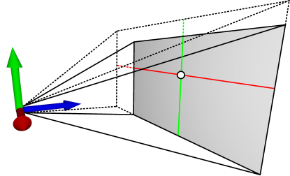
Using this sub-image region feature, it is possible to compute an off-axis projection even if the perspective camera model does not support arbitrary translation of the viewing position relative to the image plane. This can be achieved by setting a wider aspect ratio and field of view, but at the same time clipping the output image using sub-image regions. The geometrical setup for this is shown in Fig. 1, for the case where the eye position is offset to the left of the image center, and at a height slightly above the center 111The case that the eye position projects to a viewing plane coordinate outside the viewport of the application is not considered here, as the positional tracking systems of our target hardware cover about the same range as the viewing frusta.. The analogous cases with offsets to the right or bottom follow from symmetry.
LABEL:lst:strategy2 presents an exemplary implementation to set up the perspective camera given the same lower-left (LL), lower-right (LR), and upper-right (UR) corners as well as the eye position from LABEL:lst:gl as input, and that outputs the remaining extrinsic and intrinsic camera parameters, as well as a sub-image region.
Analogous to LABEL:lst:gl we first compute an orthonormal basis given by X, Y, and Z that is centered at the lower-left corner, with the z-axis pointing towards the viewer. These basis vectors give us the remaining extrinsic parameters (direction and up vectors). Again following LABEL:lst:gl we compute the distances from the camera position to the viewing plane dist, and the distance of the projection to the edges left, right, bottom, and top. These allow us to compute the new field of view and aspect ratio by comparing which of the distances is smaller; e.g., if the projected center is closer to the left edge, the new, virtual width of the viewing plane is twice the distance to the right edge (and similarly for the remaining cases). To compute the and sub-image clip region we convert from CAVE space to unit distances by dividing by the new viewport size.
With this strategy it is possible to integrate ray tracing libraries without support for off-axis camera projection into existing VR applications, given that these provide access to their viewing plane and off-axis camera representations.
2.3 Strategy 3: Generating Pinhole Cameras from Viewing Transforms
The third strategy addresses the case where the ray tracing library exposes a pinhole camera model only, and the application’s camera parameters are only available in the form of OpenGL transforms. This one is the most general of the three strategies and can serve as a fallback in any given case. Code for this strategy is provided in LABEL:lst:strategy3.
Here we make the assumption that the view to clip space transforms form a perspective frustum, i.e., neither of the constituting planes are orthogonal. This is the case for the types of cameras discussed so far. The geometric setup of this strategy is illustrated in Fig. 2. We first define the corners of the unit cube in NDC and transform them to CAVE space (Fig. 2a). We use the transformed corners to compute the left/right (Fig. 2b) and bottom/top (Fig. 2c) planes of the asymmetric viewing frustum. We compute the intersecting lines between the left/right and bottom/top planes, respectively, using the three plane intersection algorithm [\citenameGoldman 1990]. The intersecting lines have a crossing at the eye position. To avoid numerical precision issues, instead of using the intersection of the two lines in space, we conservatively compute the shortest connecting line segment between the two plane intersections and use the median of the two endpoints (which ideally are the same) as the camera position.
The screen corners are given by the far plane () of the transformed unit cube; note that generally, these are not the exact screen corners, but those of a parallel rectangle with the same aspect ratio. Given the eye position and three corners (Fig. 2d), we can compute the remaining extrinsic and intrinsic pinhole camera parameters using LABEL:lst:strategy2.
3 Evaluation
We evaluate the three different strategies qualitatively, by integrating them with different ray tracing libraries and rendering apps. We omit a performance evaluation that we believe would not be meaningful in either way. In terms of shader or device code, the second and first strategy share the exact same implementation of generating primary rays using a pinhole camera; the performance comparison would hence boil down to comparing pinhole camera ray generation to ray generation via short vector math matrix multiplication. Besides, any reasonable ray tracing application will not nearly be bottlenecked on ray generation.
We base our evaluation on ANARI [\citenameStone et al. 2022] and extend different applications to use it as a ray tracing rendering interface. Our implementations are tested with the anari-ospray device [\citenameIntel 2023] and with VisRTX [\citenameAmstutz 2023]. We further wrote an own prototypical ANARI device using the Visionaray library [\citenameZellmann et al. 2017] that does not implement all the features, but allows for more experimental code and for adding non-standard extensions 222https://github.com/szellmann/anari-visionaray.
We provide an open source demo app with sample code 333https://github.com/szellmann/anari-offaxis-sample-code that generates 3D stereo views with fixed screen configurations and that uses ANARI. Here we implemented the three camera models from Section 2. We can switch between the different configurations; the only ANARI device supporting the camera model from Section 2.1 using the inverse viewing transform and matrix multiplications is Visionaray; here we added a “matrix” camera extension that we deem useful as a general camera extension to ANARI, since it supports not only the perspective camera models described in the article, but any camera model described by OpenGL, including orthographic projection. The extension to ANARI comprises the API calls shown in LABEL:lst:anari-matrix-cam. The API adds a new camera of type “matrix”, and allows to set the model/view and projection matrices obtained from OpenGL; internally, this camera model stores inverted copies of these. Apart from the Visionaray device, neither of the ANARI implementations supports the “matrix” camera extension, which limits portability of this solution.
We extend the virtual reality renderer OpenCOVER [\citenameRantzau and Lang 1998] with an ANARI plug-in that can render fixed screen stereo camera pairs. OpenCOVER provides a plug-in API with a class that provides the OpenGL transforms required to go from CAVE space to window space and can be queried per eye and projection plane, in the form of matrices. The plug-in API also provides direct access to the frame buffer for each eye and wall, either as a pointer on the CPU, or as a CUDA “device pointer”. Our plug-in consumes the camera transforms and generates off-axis compatible pinhole camera pairs using the method from Section 2.3.
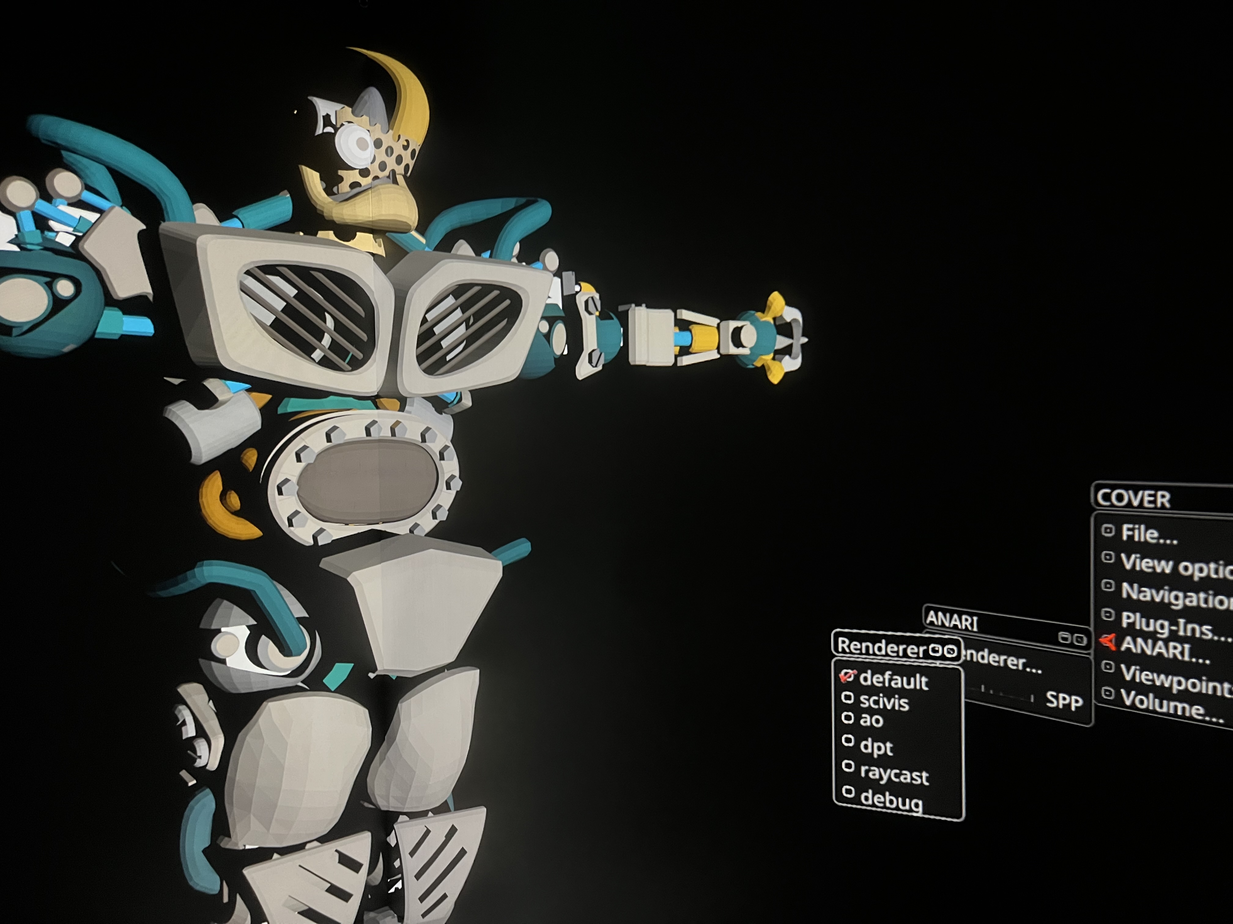
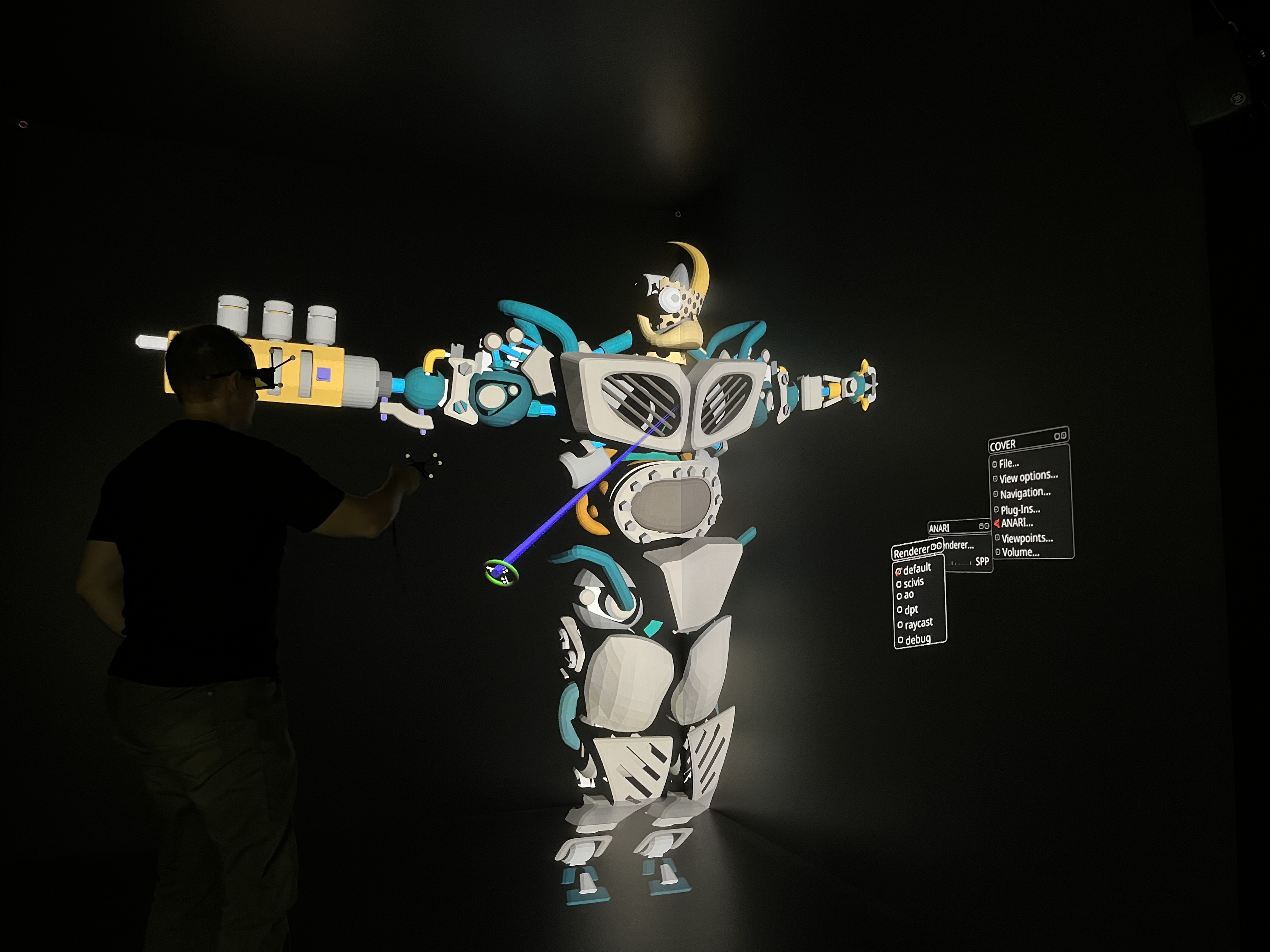
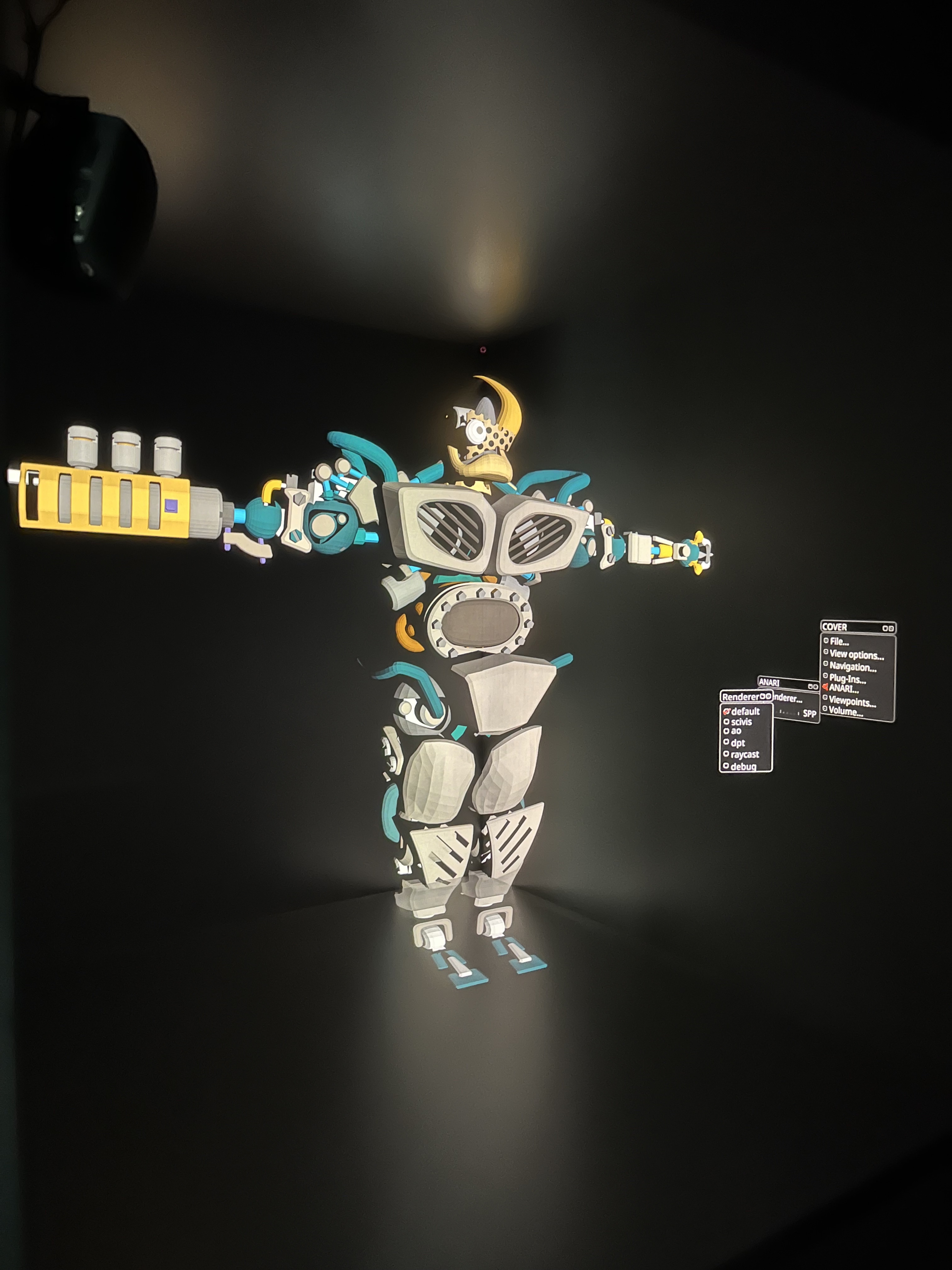
Fig. 3 shows the plug-in in use rendering with VisRTX in the five-sided CAVE virtual environment at the University of Cologne. The hardware configuration there uses active stereo projectors that are delivered side-by-side stereo images of pixels per eye per projection plane. The system is operated by a cluster with eleven NVIDIA RTX 6000 GPUs (Turing generation) (one GPU per eye, and a redundant view for the desk operator).
3.1 Limitations
The three strategies to generate stereo camera pairs are general in that they accommodate any viewing setup and ray tracing library, provided that the former at least give access to the OpenGL viewing transform, and the latter implement sub-image regions. We also found the performance of the three strategies to be equivalent—we did not encounter performance regressions, or numerical precision issues with either of the models, including the one geometrically computing the screen corner and eye coordinates in CAVE space. A limitation is that existing stereo camera implementations—which would also facilitate compositing of stereo views—cannot be used; both ANARI’s [\citenameStone et al. 2022] and OSPRay’s [\citenameWald et al. 2017] pinhole cameras have a stereo mode (which in the case of ANARI is however not implemented by a majority of the existing devices). A limitation of the methods making use of the internal pinhole camera model is that only perspective cameras are supported, while the matrix camera extension would also support other projection types.
4 Conclusion
We presented three different strategies to implement off-axis stereo cameras to generate primary rays for ray tracing in VR, with portability ranging from barely to highly portable. Each strategy has its uses within the context of different applications. We have validated their usefulness in the context of existing ray tracing libraries and VR applications. The source code accompanying the article is provided online and under a permissive open source license.
Acknowledgements
This work was supported by the Deutsche Forschungsgemeinschaft (DFG, German Research Foundation) under grant no. 456842964.
References
- [\citenameAmstutz 2023] Amstutz, J., 2023. VisRTX. Available at https://github.com/NVIDIA/VisRTX, Accessed: 21 Aug 2023.
- [\citenameCruz-Neira et al. 1992] Cruz-Neira, C., Sandin, D. J., DeFanti, T. A., Kenyon, R. V., and Hart, J. C. 1992. The CAVE: Audio Visual Experience Automatic Virtual Environment. Commun. ACM 35, 6 (jun), 64–72. URL: https://doi.org/10.1145/129888.129892, doi:10.1145/129888.129892.
- [\citenameGoldman 1990] Goldman, R. 1990. Graphics Gems. Academic Press Professional, Inc., USA, ch. Intersection of Three Planes, 305.
- [\citenameIntel 2023] Intel, 2023. ANARI-OSPRay—Translation layer from Khronos ANARI to Intel OSPRay: ANARILibrary and ANARIDevice “ospray”.). Available at https://github.com/ospray/anari-ospray, Accessed: 21 Aug 2023.
- [\citenameMartin et al. 2018] Martin, K., DeMarle, D., Jhhaveri, S., and Ayachit, U., 2018. Taking ParaView into Virtual Reality. Available at https://www.kitware.com/taking-paraview-into-virtual-reality/, Accessed: 13 August 2023.
- [\citenameNam et al. 2023] Nam, J. W., Abram, G. D., Samsel, F., and Navrátil, P. A. 2023. Immersive OSPRay: Enabling VR Experiences with OSPRay. In PEARC: Practice and Experience in Advanced Research Computing (PEARC 2023). preprint. URL: https://jungwhonam.github.io/images/publications/PEARC2023_Immersive-OSPRay.pdf, doi:10.1145/3569951.3597579.
- [\citenamePape 2005] Pape, D., 2005. Computing the CAVE Projection Transformation. Available at https://www.evl.uic.edu/pape/caveproj/, Accessed: 10 Aug 2023.
- [\citenameRantzau and Lang 1998] Rantzau, D., and Lang, U. 1998. A Scalable Virtual Environment for Large Scale Scientific Data Analysis. Future Generation Computer Systems 14, 3, 215–222. Virtual Reality in Industy and Research. URL: https://www.sciencedirect.com/science/article/pii/S0167739X98000259, doi:https://doi.org/10.1016/S0167-739X(98)00025-9.
- [\citenameStone et al. 2022] Stone, J. E., Griffin, K. S., Amstutz, J., DeMarle, D. E., Sherman, W. R., and Günther, J. 2022. ANARI: A 3-D Rendering API Standard. Computing in Science & Engineering 24, 2, 7–18. URL: https://ieeexplore.ieee.org/document/9745399, doi:10.1109/MCSE.2022.3163151.
- [\citenameSuffern 2007] Suffern, K. 2007. Ray Tracing from the Ground Up, 1st ed. A K Peters / CRC Press, ch. 12: Stereoscopy, 197–215. URL: https://www.taylorfrancis.com/chapters/mono/10.1201/b10675-12/stereoscopy-kevin-suffern.
- [\citenameWald et al. 2017] Wald, I., Johnson, G., Amstutz, J., Brownlee, C., Knoll, A., Jeffers, J., Günther, J., and Navratil, P. 2017. OSPRay - A CPU Ray Tracing Framework for Scientific Visualization. IEEE Transactions on Visualization and Computer Graphics 23, 1, 931–940. URL: https://ieeexplore.ieee.org/abstract/document/7539599, doi:10.1109/TVCG.2016.2599041.
- [\citenameYuan et al. 2007] Yuan, P., Wang, S., Zhang, J., and Liu, H. 2007. Virtual Reality Platform Based on Open Sourced Graphics Toolkit OpenSceneGraph. In 2007 10th IEEE International Conference on Computer-Aided Design and Computer Graphics, 361–364. URL: https://ieeexplore.ieee.org/abstract/document/4407909, doi:10.1109/CADCG.2007.4407909.
- [\citenameZellmann et al. 2017] Zellmann, S., Wickeroth, D., and Lang, U. 2017. Visionaray: A cross-platform ray tracing template library. In 2017 IEEE 10th Workshop on Software Engineering and Architectures for Realtime Interactive Systems (SEARIS), 1–8. URL: https://ieeexplore.ieee.org/document/9183547, doi:10.1109/SEARIS41720.2017.9183547.
- [\citenameZellmann 2014] Zellmann, S. 2014. Interactive High Performance Volume Rendering. PhD thesis, University of Cologne, Albertus-Magnus-Platz, 50923 Cologne, GER. Chapter 5.1.1, pp. 81–86. URL: http://kups.ub.uni-koeln.de/5727/.