Verilog-to-PyG – A Framework for Graph Learning and Augmentation on RTL Designs
Abstract
The complexity of modern hardware designs necessitates advanced methodologies for optimizing and analyzing modern digital systems. In recent times, machine learning (ML) methodologies have emerged as potent instruments for assessing design quality-of-results at the Register-Transfer Level (RTL) or Boolean level, aiming to expedite design exploration of advanced RTL configurations. In this presentation, we introduce an innovative open-source framework that translates RTL designs into graph representation foundations, which can be seamlessly integrated with the PyTorch Geometric graph learning platform. Furthermore, the Verilog-to-PyG (V2PYG) framework is compatible with the open-source Electronic Design Automation (EDA) toolchain OpenROAD, facilitating the collection of labeled datasets in an utterly open-source manner. Additionally, we will present novel RTL data augmentation methods (incorporated in our framework) that enable functional equivalent design augmentation for the construction of an extensive graph-based RTL design database. Lastly, we will showcase several using cases of V2PYG with detailed scripting examples. V2PYG can be found at https://yu-maryland.github.io/Verilog-to-PyG/.
I Introduction
The increasing complexity of electronic systems has driven significant advancements in hardware design. Modern hardware designs encompass a wide range of components, from Register Transfer Level (RTL) descriptions to logic circuits. As the complexity grows, conventional design algorithms can suffer from their exponentially increased runtime overhead, resulting in sub-optimal solutions as the optimization search space is too large to be explored. Thus, an effective optimization and analysis technique becomes more critical.
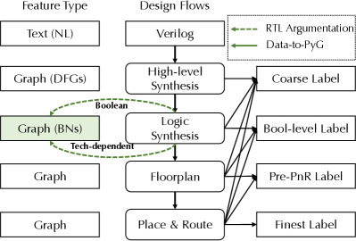
Recently, machine learning (ML), which features with its data-driven generalizability, has been applied to computer systems and electronic design automation (EDA) tasks [35, 20, 42, 40, 25, 43, 11] as an alternative to conventional solutions. As shown in Figure 1, the optimization target in each design flow can be converted to a specific ML task. For example, for the high-level synthesis, the optimization target is the Data Flow Graphs (DFGs) [28, 39, 38, 36, 32], which can be formulated as graph learning problems. Similarly, for logic synthesis, the optimization target, Boolean Networks (BNs), can be formulated as graphs and applicable to graph learning. As a result, graph neural networks (GNNs) have been applied to classifying sub-circuit functionality from gate-level netlists [3, 30, 34], analyzing the impacts of logic rewriting [44], predicting arithmetic block boundaries [14], and improving design exploration fidelity[28].
Specifically, graph learning, particularly graph neural networks (GNNs), has emerged as a powerful method for understanding complex relationships in various domains, including social networks, biological systems, and natural language processing. In the context of hardware design, graph learning can be employed to model and analyze the intricate connections among design components, such as gates, wires, and registers, to optimize design performance and effectively analyze design characteristics. Furthermore, the embedding and features encoded within the graph, i.e., the dataset for GNNs, play a vital role in the GL performance regarding the hardware design [34].
However, when it comes to applying graph learning to RTL designs, there is a notable gap in support for dataset preparation, specifically in the graph representations of these designs. Two main challenges exist: 1) The absence of a comprehensive infrastructure that links RTL designs to graph representations, aids in the construction of graph datasets, and integrates seamlessly with existing graph learning and EDA frameworks such as PyTorch Geometric (PyG) [13] and OpenROAD [1]. 2) A limited range of design variations available for training and constrained search spaces for foundational RTL models, which necessitates the development of effective RTL design augmentation techniques. To tackle these challenges, we introduce an open-source infrastructure that is compatible with PyG [13] and enriches the pool of RTL design samples through functionally equivalent RTL augmentations.
In this paper, we focus on the graph data representations of RTL designs at the Boolean network level, as highlighted in the green box of Figure 1. The paper is organized as follows: Section II offers background information pertinent to graph-represented RTL designs. Section III presents our framework, including design-specific graph generation (Section III-B) and Section IV-A illustrates dataset augmentations for a variety of graph structures that retain the same design function. Finally, we discuss the implementation of our framework (Section V-A) in ABC [6, 23], complemented by detailed user examples (Section V-B) and demonstrations of equivalence checking verification.
II Background
II-A Graph Learning on RTL Designs
Since BNs and circuit netlists are naturally represented as graphs, GNNs can be leveraged to classify sub-circuit functionality from gate-level netlists [3], predict the functionality of approximate circuits [7], analyze impacts of circuit rewriting on functional operator detection [44], and predict boundaries of arithmetic blocks [14, 30, 29, 34]. Promising as they are, these approaches focus on graphs with tens of thousands of nodes and conduct training on complex designs and inference on relatively simpler ones, in which the generalization capability from simple to complex designs is not well examined. To address such challenges in learning on logic graphs, representing logic graph using universal representations have shown significant improvements in generalizability and scalability. For example, the uses of And-Inv-Graph (AIGs) has significantly boosted the performance and generaliability in contrastive graph learning [44, 16, 26, 29], node classification based tasks, and reasoning [34]. Moreover, in DFGs or similar graph representations, GNNs have also shown great potential in datapath optimization, compiler optimization, and multi-fidelity optimization such as placement and floorplanning [32, 33, 28, 17, 18, 19].
Moreover, GNNs operate by propagating information along the edges of a given graph. Each node is initialized with a representation, which could be either a direct representation or a learnable embedding obtained from node features. Then, a GNN layer updates each node representation by integrating node representations of both itself and its neighbors in the graph. The propagation along edges extracts structural information from graphs, corresponding to structural shape hashing in conventional reasoning; after encoding Boolean functionality into node features, neighborhood aggregation is analogous to functional aggregation in conventional reasoning. Thus, the inherent message-passing mechanism in GNNs enables simultaneous handling of structural and functional information. This is analogous to conventional reasoning [34, 29], where GNNs aggregate functional and structural approaches simultaneously.
II-B DAG-aware Logic Synthesis
When applying graph learning to hardware designs, the dataset is prepared to include various graph structures even with the same functionality, which requires the framework to be able to provide graph augmentation for the dataset generation. In logic synthesis, design variations can be generated with different logic optimization methods and different technology mapping methods.
In logic optimization, which is conducted on the uniform functionality representation (here, we use AIG representation as a demonstration), there are mainly three methods.
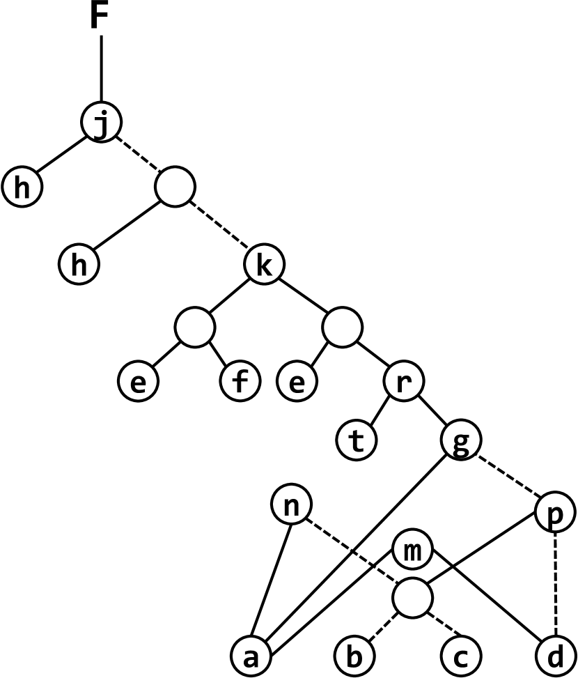
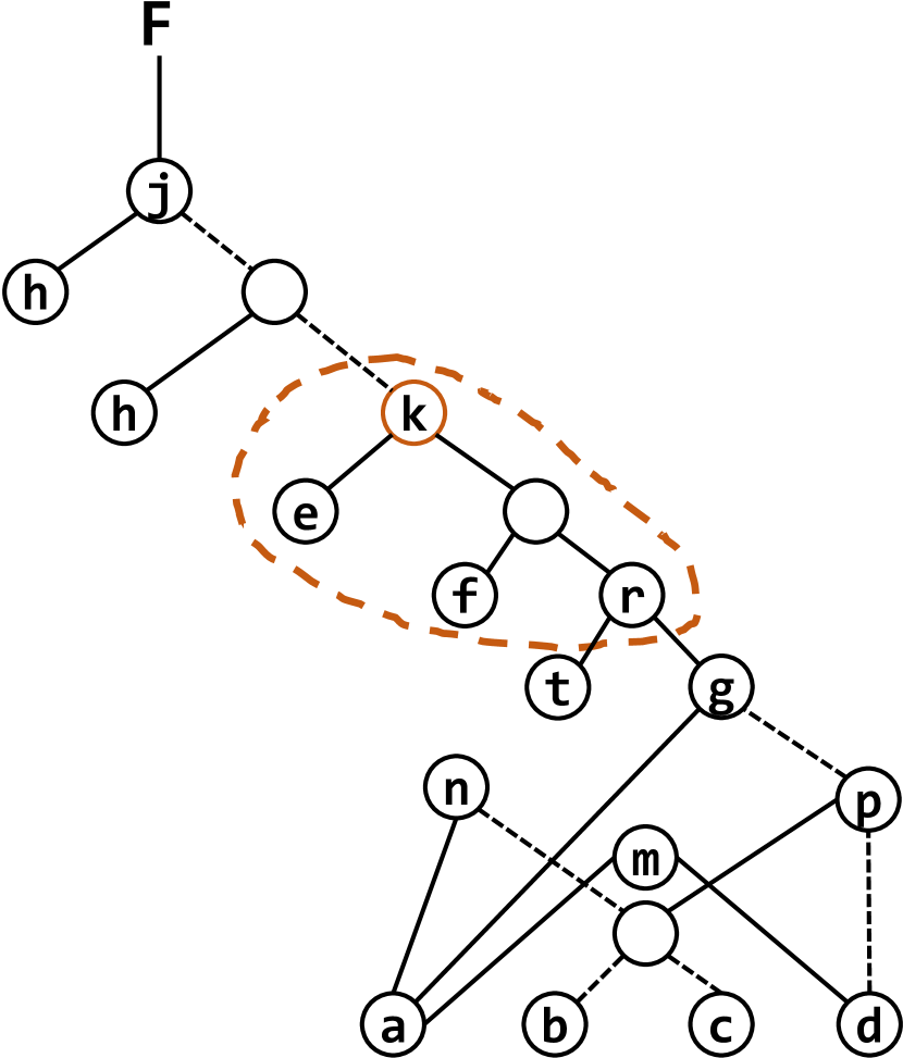
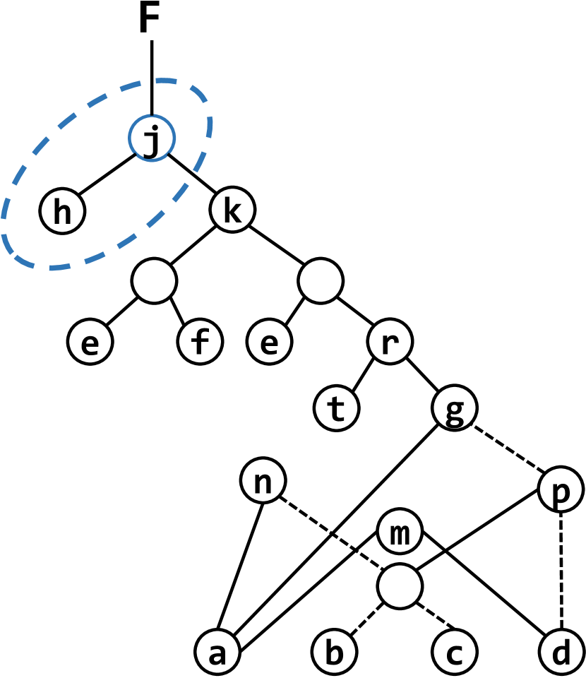
Rewriting, noted as rw, is a fast greedy algorithm for optimizing the graph size. It iteratively selects the AIG subgraph with the current node as the root node and replaces the selected subgraph with the same functional pre-computed subgraph with a smaller (or equal) size to realize the graph size reduction. Specifically, it finds the 4-feasible cuts as subgraphs for the node while preserving the number of logic levels [21]. As shown in Figure 2, the graph structure alters from Figure 2(a) to Figure 2(b) when applied with rw at node k.
Refactoring, noted as rf, is a variation of the AIG rewriting using a heuristic algorithm [5] to produce a large cut for each AIG node. Refactoring optimizes AIGs by replacing the current AIG structure with a factored form of the cut function. It can also optimize the AIGs with the graph depth. The rf optimization applied at node j alters the graph structure as shown in Figure 2(c).
Resubstitution, noted as rs, optimizes the AIG by replacing the function of the node with the other existing nodes (divisors) already present in the graph, which is expected to remove the redundant node in expressing the function of the current node. The optimized graph resulting from rs optimization is shown in Figure 2(d).
Thus, by applying different logic optimization methods to the same AIG, different AIG structures with the same functionality can be generated. In our framework, we further expand the variations by applying different optimizations at each node for combinational augmentation. For example, for an AIG graph with a node size of , the variation space can be .
With different graph structures with AIG representation, the netlist variation of hardware design can be realized by technology mapping from various AIGs with the technology library.
III V2PyG Framework
III-A Overview
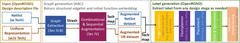
The framework overview is shown in Figure 3. V2PYG currently performs Verilog to graph representation at the foundation of Boolean representations, including technology dependent (technology mapped) and technology independent representations (Boolean networks such as And-Inv-Graphs). V2PYG parses Verilog designs using Yosys front-end and performs downstream design flow via OpenROAD. First, we represent sequential design as combinational design in a special case. First, transform the sequential design into an equivalent design using Boolean network data structure (e.g., AIGs) or technology dependent networks (exact topology of mapped netlist). Next, model flip-flops as pseudo-primary inputs (PPIs) and pseudo-primary outputs (PPOs), connecting them through the AIG network to capture state transitions and dependencies between flip-flops and combinatorial logic. The graph is then extracted from the network, and the graph dataset is augmented with combinational methods in logic optimization as shown in Alg. 1, which will return the structural information of the edgelist of the graph and the initial functional embedding for graph learning tasks. Data labels will be generated via OpenROAD [2] downstream flow. As a result, the sequential design will be represented in semi-complete multi-DAGs. We also plan to integrate MLIR CIRCT [12] into the pipeline to process multi-fidelity graph representations (DFGs w Boolean networks).
III-B Verilog to Graph Representation
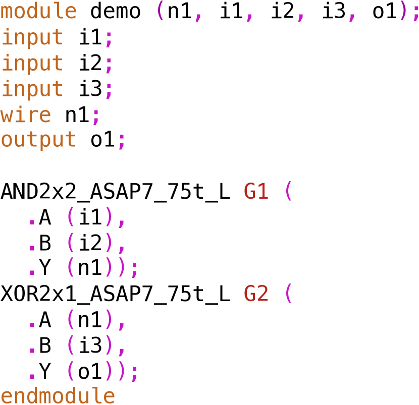
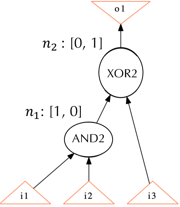
After the prepossessing by Yosys, the design is described at the RTL level, where the gates are connected with nets. As shown in Figure 4, in the Verilog file, gate , which is an AND2 gate, and gate , which is an XOR2 gate, are connected with net . Thus, we can extract and as two nodes, and , with features indicting the different gate types. In Figure 4(b), the gate type is encoded with one-hot representation, e.g., indicates the gate type is AND2 and indicates the gate type is XOR2 for this design. Net is formulated as the edge between n1 and n2 with the direction from to indicating the connection between two gates, i.e., following the topological order, is at least one level higher than .
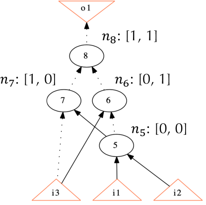
Furthermore, in the logic optimization step, the optimizations are conducted on multi-level technology-independent representations such as And-Inverter-Graphs (AIGs) [21, 22, 41] and Majority-Inverter-Graphs (MIGs) [4, 27] of the digital logic, and XOR-rich representations for emerging technologies such as XOR-And-Graphs [8] and XOR-Majority-Graphs, which means the gate-level netlist is first strashed into uniform representations with the same functionality. For example, to strash the netlist in Figure 4(a) to AIG, where all gates functions are implemented with only 2-input AND gates and inverters, the XOR2 is strashed into three AND2 gates and five Inverters. Thus, as shown in Figure 4(c), to extract AIGs to graphs, we formulate AND2 gates as nodes, – , with exact two inputs, and the inverter is encoded at the input net of the AND2 gate, where the dashed edge indicates an inverter is applied at the net. The initial node embedding indicates the inverters at its input edges from left to right with exact two dimensions with bit representation, where indicates the inverter at the input and indicates no inverter at the input. For example, for node , there are inverters at both inputs of the gate. Thus, its initial node embedding is , while for node , there is only one inverter at its left input, the initial node embedding is .
For each graph, the framework will return the edgelist for structure information and initial node embedding for the functional information, such as the gate type for the netlist graph and the input inverters for AIGs.
IV V2PYG RTL Augmentation
In the realm of hardware design, specifically at the register-transfer level (RTL), the idea of leveraging machine learning (ML) techniques to enhance optimization processes has garnered increasing attention. However, one significant challenge lies in the acquisition and augmentation of RTL design data to train these ML models effectively. In traditional domains where ML has shown success, such as computer vision or natural language processing, data augmentation techniques—like image rotation, scaling, or text paraphrasing—have been pivotal in enhancing model robustness and generalization. Yet, in the context of RTL design, naive data augmentation can lead to functionally incorrect or non-equivalent designs. Ensuring functional equivalence is paramount; thus, data augmentation in this space requires meticulous care and deep domain knowledge, preventing the straightforward application of techniques that have been successful in other domains. Consequently, while the potential of ML to revolutionize RTL optimization is evident, the unique nature of hardware design data and the stringent requirements for functional correctness substantially complicate the application of traditional data augmentation strategies.
IV-A Combinational Augmentation
The combinational augmentation of RTL designs can be achieved through V2PYG by applying transformations that maintain combinational equivalence, inspired by [9, 10] Specifically, V2PYG incorporates data flow augmentation using polynomial manipulations, fine-grained Boolean algebra manipulation (at least at the individual Boolean node level), and graph isomorphism augmentation. These augmentation techniques enable the generation of a nearly unlimited number of functionally equivalent designs at the Boolean level. As discussed in Section II, applying different logic optimizations to the same functional AIG can result in various graph structures. However, stand-alone logic optimizations are limited in graph augmentation. With three optimizations, i.e., rw, rs, rf, only three variations are generated for the same original AIG. Thus, we propose combinational augmentation, where we randomly apply different optimizations at each AIG node for graph structure alterations. For an original AIG with a node size of , the potential graph variations can be at the scale of , and the variation space increases exponentially as the graph size increases.
The algorithm for augmentation with combinational logic optimization methods is shown in Alg. 1. It takes the original AIG and a random seed as inputs. Following the topological order in the original graph, it first initializes a list for recording the available optimizations, where we hash the optimizations with numbers , , , , i.e., indicates none of the optimizations is applied, which is initialized for all AIG nodes to be considered in the random pool; indicates rw is applicable for logic optimization at the node; indicates rf is applicable for optimization at the node; indicates rs is applicable for optimization at the node. Then, for each AIG node, it generates the list for random selections by checking the transformability for each optimization operation from line 3 to line 8. After acquiring the list with all available optimizations, it randomly selects the optimization from (line 9) and updates the graph accordingly (line 10). Note that the resulting AIG structures from different optimizations are checked to be functional equivalence by Combinatorial Equivalence Checking (CEC).
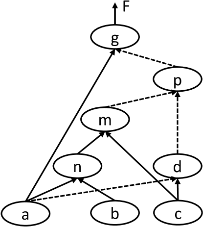
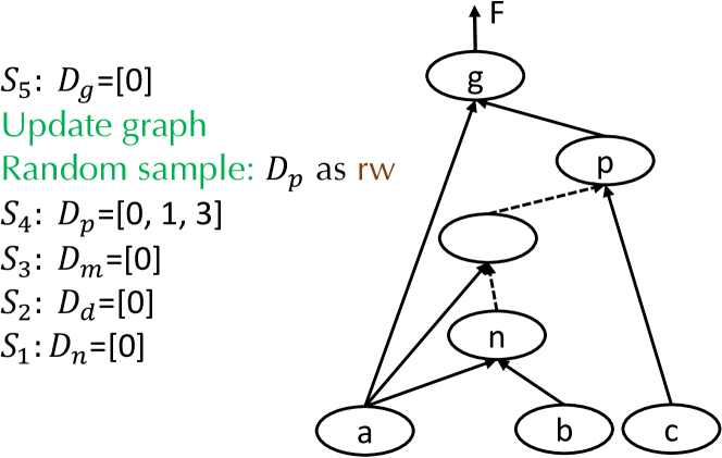
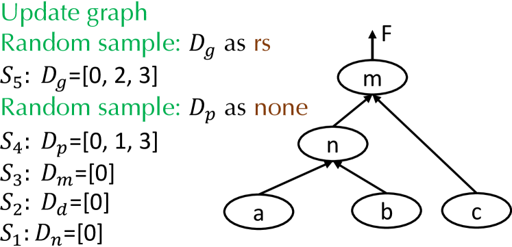
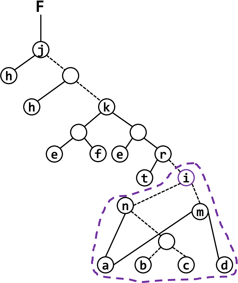
For example, in Figure 5, the original AIG is shown in Figure 5(a). The algorithm checks the optimization transformability following the topological order starting from as shown in Figure 5(a). For node , they have no applicable optimizations for selection and are skipped for optimization. Regarding node , it poses three optimizations, and the random selection can result in quite different graph structures for dataset augmentation. In the first random sample, the algorithm picks for the optimization at node and the graph is updated to Figure 5(b) thus, node shows no applicable optimizations. In the second random sample, the algorithm picks for the optimization at node , resulting in optimization opportunities for node . When the algorithm picks for the optimization at , the graph is updated as shown in Figure 5(c). By setting different random seeds and starting the random sample with a push button implemented in our framework, the dataset is augmented through combinational random selections with functional equivalence.
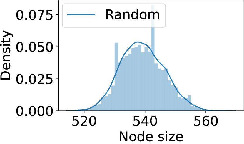
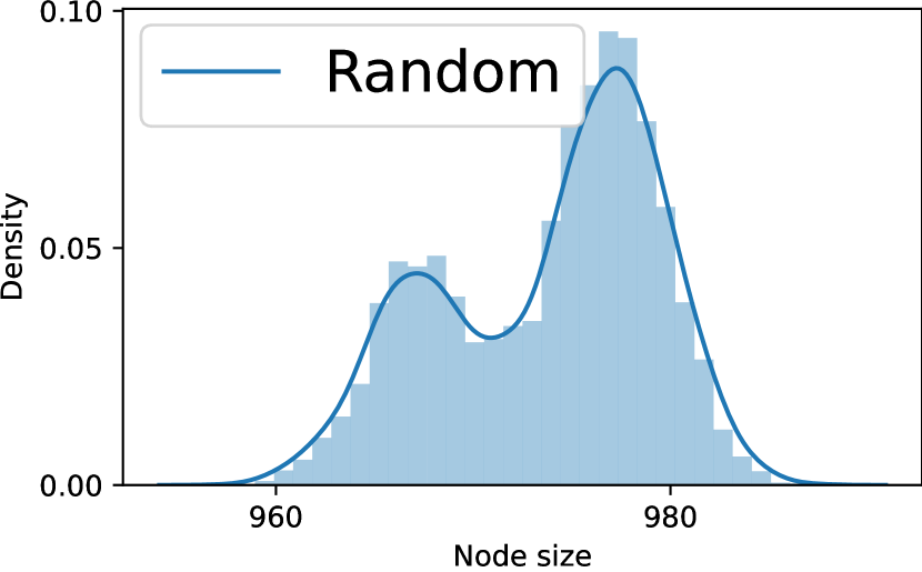
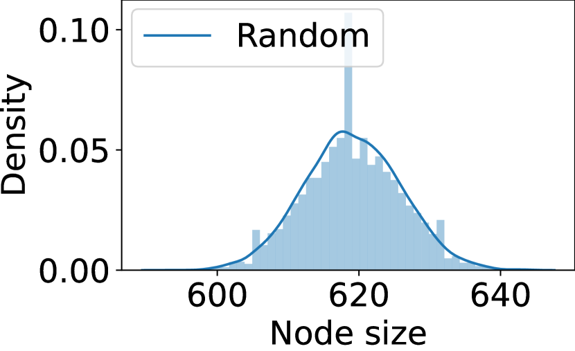
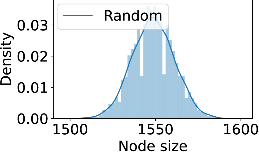
Furthermore, we show the dataset distribution with 6000 samples in Figure 6 for different designs with Alg. 1. Here, we collect the distribution w.r.t the graph size of various graph structures, which is reported by the logic synthesis in OpenROAD as labels. By combinational dataset augmentation, we can generate large enough datasets, and with the proposed random selected logic-optimization-based boolean manipulations on graphs, we can generate Gaussian-like dataset distributions for effective GL model training efficiently.
IV-B Sequential Augmentation
V2PYG currently supports sequential augmentation by adjusting the sequential behaviors using partial random retiming, which offers significant design variations while preserving sequential equivalence. It is important to note that combinational augmentation is orthogonal to sequential augmentation.
In the sequential augmentation, we use the variations in retiming, where we first check the feasibility of each edge for buffer insertion and randomly insert the buffer at the applicable edge, i.e., resulting in random partitions of the sequential graph. After sequential augmentation, we can further apply combinational augmentation on each sub-graph resulting from sequential augmentations.
IV-C Label Generation
In Figure 6, multiple labels can be derived for a specific RTL design. For example, the quality metrics related to the AIG size, demonstrated in Figure 6, signify one category of labels formulated during the logic synthesis stage of ABC. Alongside technology-independent representation labels, technology-dependent labels at the logic level are adeptly generated through design infrastructures such as ABC. Other ABC-compatible platforms like OpenROAD [1], Yosys [31], and VTR [24] also support this functionality. By harnessing technology mapping in tools like ABC and Yosys and utilizing methods such as LUT-mapping (e.g., ’if’ in ABC) or standard-cell mapping (e.g., ’map’), we can generate labels for metrics encompassing the number of LUTs, LUT-based netlist depth, and delay and area metrics of the standard-cell netlist.
Additionally, while V2PYG is inherently integrated with ABC, it offers potential integration with OpenROAD to acquire downstream data labels, including those from floorplanning, placement, and routing stages. Specifically, via the Yosys ABC interface (command abc in Yosys), V2PYG functionalities can be seamlessly incorporated into the OpenROAD flow. In this scenario, we can garner custom labels at specific design phases, virtually spanning the complete design procedure. For instance, each sampled AIG graph can be channeled to OpenROAD for subsequent design phases like technology mapping, floorplanning, placement, and routing. Following each stage, OpenROAD renders a design report, which can be mined to extract labels, thereby training GNN models tailored for diverse tasks.
V V2PYG Implementation
V-A Implementation
Graph Extraction
We have introduced a universal extraction implementation write_edgelist, which supports the extraction for AIGs, standard-cell techmap netlist, and LUT-based netlist. More details of the usage can be found by write_edgelist -h in ABC and the following user case examples.
Logic-level augmentation
This framework has been implemented in ABC [6] with the command aigaug, which conducts logic optimization based combinational augmentation of the design with uniform representations following Alg. 1. Specifically, we implement five flags in aigaug – (1) ‘-s‘ takes in the customized random seed for the random selections; (2) ‘-d‘ sets the name of the file recording the random selected and applied optimization operation at each node; (2) ‘-z‘ enables the zero usage for rewrite optimization, where the graph structure is altered even when there is no graph size reduction by rewrite; (4) ‘-Z‘ enables the zero usage for refactor optimization, where the graph structure is altered even when there is no graph size reduction by refactor; (5) ‘-help‘ prints out the usage of the command.
V-B User Example 1 - Combinational RTL Designs
In this section, we present the toy example that demonstrates a series of functions associated with V2PYG implemented in ABC using a 2-bit multiplier. Our starting point is an RTL implementation of a 2-bit multiplier shown in Listing 1.
To translate the word-level description of our 2-bit multiplier into an AIG representation, we employ a sequential procedure within the ABC tool, as illustrated in Listing 2.
In the above commands, ‘%read mult-2b.v ; %blast‘ facilitates the reading of our multiplier’s Verilog code, subsequently bit-blasting it to a bit-level representation. The sequence ‘&put;strash‘ then morphs the design into its AIG avatar. Lastly, the user can serialize the AIG representation to a BLIF format using ‘write mult-2b.blif‘. This pedagogical demonstration serves as a testament to ABC’s prowess in handling and transforming RTL designs, marking its indelible significance in the RTL design landscape.
AIG
Gate-level netlist
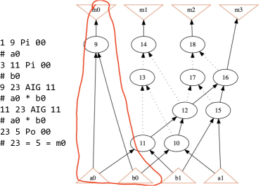
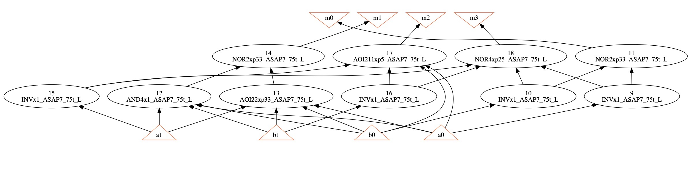
Next, we will illustrate a case study in ABC for generating an edge list of the mapped netlist. This list succinctly encapsulates the interconnections of the design’s elements, providing a blueprint of its topology. The format and contents of the edge list for our 2-bit multiplier are showcased in Listing 4, which can be matched from Figure 8. In addition to the topological information (connectivity), the edgelist contains the exact cell entry of the technology library. In this example, the cell matches the ASAP7 library, e.g., INVx1_ASAP7_75t_L indicates the functionality of the cell, the size of the cell, and its library information. Note that we plan to further expand the functionality of feature extract for technology mapped cells, such as adding more feature columns for the cell information, such as capacitor size, rise/fall timing, area, etc.
V-C Equivalence Verification of Augmented Designs
In the intricate domain of RTL design, demonstrating functional equivalence in data-augmented designs is paramount. To elucidate this, consider the scenario executed using the abc tool, renowned for And-Inverter Graph (AIG) manipulation. Initially, the design i10.aig is loaded. Post structural hashing (strash), the design encapsulates 257 inputs, 224 outputs, and leverages 2675 AND gates. To perform data augmentation, a random seed of ‘0‘ is deployed, birthing the augmented design i10_aug_0.aig. The statistics of this new design reveal modifications, notably a decrement in AND gates to 2514, albeit retaining an identical level depth. Mirroring this procedure but employing a divergent random seed of ‘1‘, we derive another offspring, the i10_aug_1.aig. The design, now slightly deviant, holds 1980 AND gates within a level depth of 47. Most crucially, upon deploying the combinational equivalence checking (cec), results affirm that the parent i10.aig and its progenies i10_aug_0.aig and i10_aug_1.aig are, in essence, functionally equivalent. This not only underscores the power and precision of such tools but also the intricate art of RTL data augmentation where functional integrity remains inviolate.
VI Conclusion
This paper proposes a novel framework V2PYG to address the growing complexities in modern hardware designs by introducing advanced methodologies for optimizing and analyzing digital systems. We have introduced an innovative, open-source framework known as Verilog-to-PyG (V2PYG) that enables seamless integration with the PyTorch Geometric graph learning platform [13]. This framework also offers compatibility with the open-source Electronic Design Automation (EDA) toolchain OpenROAD, Yosys, and VTR, thereby facilitating the collection of labeled datasets in a fully open-source environment. Moreover, we presented novel techniques for RTL data augmentation that can be incorporated into our framework. These methods contribute to the development of an extensive database of graph-based RTL designs validated in equivalence checking verification.
References
- [1] T. Ajayi, D. Blaauw, T. Chan, C. Cheng, V. Chhabria, D. Choo, M. Coltella, S. Dobre, R. Dreslinski, M. Fogaça et al., “Openroad: Toward a self-driving, open-source digital layout implementation tool chain,” Proc. GOMACTECH, pp. 1105–1110, 2019.
- [2] T. Ajayi et al., “Toward an open-source digital flow: First learnings from the openroad project,” in DAC, 2019, pp. 1–4.
- [3] L. Alrahis et al., “Gnn-re: Graph neural networks for reverse engineering of gate-level netlists,” IEEE TCAD, 2021.
- [4] L. Amaru, P.-E. Gaillardon, and G. De Micheli, “Majority-inverter graph: A new paradigm for logic optimization,” IEEE Transactions on CAD, vol. 35, no. 5, pp. 806–819, 2015.
- [5] A. M. R. Brayton, “Scalable logic synthesis using a simple circuit structure,” in Proc. IWLS, vol. 6, 2006, pp. 15–22.
- [6] R. Brayton and A. Mishchenko, “Abc: An academic industrial-strength verification tool,” in Proc. CAV. Springer, 2010.
- [7] T. Bucher et al., “Appgnn: Approximation-aware functional reverse engineering using graph neural networks,” arXiv:2208.10868, 2022.
- [8] Ç. Çalık, M. Sönmez Turan, and R. Peralta, “The multiplicative complexity of 6-variable boolean functions,” Cryptography and Communications, vol. 11, no. 1, pp. 93–107, 2019.
- [9] A. B. Chowdhury, L. Alrahis, L. Collini, J. Knechtel, R. Karri, S. Garg, O. Sinanoglu, and B. Tan, “Almost: Adversarial learning to mitigate oracle-less ml attacks via synthesis tuning,” arXiv preprint arXiv:2303.03372, 2023.
- [10] A. B. Chowdhury, M. Romanelli, B. Tan, R. Karri, and S. Garg, “Invictus: Optimizing boolean logic circuit synthesis via synergistic learning and search,” arXiv preprint arXiv:2305.13164, 2023.
- [11] A. B. Chowdhury, B. Tan, R. Carey, T. Jain, R. Karri, and S. Garg, “Bulls-eye: Active few-shot learning guided logic synthesis,” IEEE Transactions on Computer-Aided Design of Integrated Circuits and Systems, 2022.
- [12] C. Developers, “"circt" / circuit ir compilers and tools. github.com/llvm/circt,” 2019, pp. 1–4.
- [13] M. Fey and J. E. Lenssen, “Fast graph representation learning with pytorch geometric,” arXiv preprint arXiv:1903.02428, 2019.
- [14] Z. He et al., “Graph learning-based arithmetic block identification,” in Proc. ICCAD, 2021.
- [15] C. E. Leiserson and J. B. Saxe, “Retiming synchronous circuitry,” Algorithmica, vol. 6, no. 1-6, pp. 5–35, 1991.
- [16] M. Li, S. Khan, Z. Shi, N. Wang, H. Yu, and Q. Xu, “Deepgate: Learning neural representations of logic gates,” in Proceedings of the 59th ACM/IEEE Design Automation Conference, 2022, pp. 667–672.
- [17] Z. Li, D. Wu, D. Wijerathne, and T. Mitra, “Lisa: Graph neural network based portable mapping on spatial accelerators,” in 2022 IEEE International Symposium on High-Performance Computer Architecture (HPCA). IEEE, 2022, pp. 444–459.
- [18] Y.-C. Lu, S. Pentapati, and S. K. Lim, “Vlsi placement optimization using graph neural networks,” in Proceedings of the 34th Advances in Neural Information Processing Systems (NeurIPS) Workshop on ML for Systems, Virtual, 2020, pp. 6–12.
- [19] Y.-C. Lu, S. Pentapati, and S. K. Lim, “The law of attraction: Affinity-aware placement optimization using graph neural networks,” in Proceedings of the 2021 International Symposium on Physical Design, 2021, pp. 7–14.
- [20] A. Mirhoseini, A. Goldie, M. Yazgan, J. Jiang, E. Songhori, S. Wang, Y.-J. Lee, E. Johnson, O. Pathak, S. Bae et al., “Chip placement with deep reinforcement learning,” arXiv preprint arXiv:2004.10746, 2020.
- [21] A. Mishchenko, S. Chatterjee, and R. Brayton, “DAG-aware AIG Rewriting: A Fresh Look at Combinational Logic Synthesis,” in Design Automation Conference (DAC), 2006, pp. 532–535.
- [22] A. Mishchenko, S. Chatterjee, R. Jiang, and R. K. Brayton, “Fraigs: A unifying representation for logic synthesis and verification,” ERL Technical Report, Tech. Rep., 2005.
- [23] A. Mishchenko et al., “Abc: A system for sequential synthesis and verification,” URL http://www. eecs. berkeley. edu/alanmi/abc, vol. 17, 2007.
- [24] K. E. Murray et al., “VTR 8: High-performance CAD and Customizable FPGA Architecture Modelling,” ACM Transactions on Reconfigurable Technology and Systems (TRETS), vol. 13, no. 2, pp. 1–55, 2020.
- [25] W. L. Neto, Y. Li, P.-E. Gaillardon, and C. Yu, “Flowtune: End-to-end automatic logic optimization exploration via domain-specific multi-armed bandit,” IEEE Transactions on Computer-Aided Design of Integrated Circuits and Systems, 2022.
- [26] Z. Shi, H. Pan, S. Khan, M. Li, Y. Liu, J. Huang, H.-L. Zhen, M. Yuan, Z. Chu, and Q. Xu, “Deepgate2: Functionality-aware circuit representation learning,” arXiv preprint arXiv:2305.16373, 2023.
- [27] M. Soeken, L. G. Amaru, P.-E. Gaillardon, and G. De Micheli, “Exact synthesis of majority-inverter graphs and its applications,” IEEE Transactions on CAD (TCAD), 2017.
- [28] E. Ustun, C. Deng, D. Pal, Z. Li, and Z. Zhang, “Accurate operation delay prediction for fpga hls using graph neural networks,” in Proceedings of the 39th international conference on computer-aided design, 2020, pp. 1–9.
- [29] Z. Wang, C. Bai, Z. He, G. Zhang, Q. Xu, T.-Y. Ho, B. Yu, and Y. Huang, “Functionality matters in netlist representation learning,” in Proceedings of the 59th ACM/IEEE Design Automation Conference, 2022, pp. 61–66.
- [30] Z. Wang, Z. He, C. Bai, H. Yang, and B. Yu, “Efficient arithmetic block identification with graph learning and network-flow,” IEEE Transactions on Computer-Aided Design of Integrated Circuits and Systems, 2022.
- [31] C. Wolf, “Yosys open synthesis suite,” 2016.
- [32] N. Wu et al., “High-level synthesis performance prediction using gnns: Benchmarking, modeling, and advancing,” in Proc. DAC, 2022.
- [33] N. Wu et al., “Lostin: Logic optimization via spatio-temporal information with hybrid graph models,” in Proc. ASAP, 2022.
- [34] N. Wu, Y. Li, C. Hao, S. Dai, C. Yu, and Y. Xie, “Gamora: Graph learning based symbolic reasoning for large-scale boolean networks,” DAC, 2023.
- [35] N. Wu and Y. Xie, “A survey of machine learning for computer architecture and systems,” ACM Comput. Surveys, 2022.
- [36] N. Wu, Y. Xie, and C. Hao, “Ironman: Gnn-assisted design space exploration in high-level synthesis via reinforcement learning,” in Proceedings of the 2021 on Great Lakes Symposium on VLSI, 2021, pp. 39–44.
- [37] X. Xu et al., “Standard cell library design and optimization methodology for asap7 pdk,” in Proc. ICCAD, 2017.
- [38] J. Yin, Y. Li, D. Robinson, and C. Yu, “Respect: Reinforcement learning based edge scheduling on pipelined coral edge tpus,” arXiv preprint arXiv:2304.04716, 2023.
- [39] J. Yin and C. Yu, “Accelerating exact combinatorial optimization via rl-based initialization–a case study in scheduling,” arXiv preprint arXiv:2308.11652, 2023.
- [40] C. Yu, “Flowtune: Practical multi-armed bandits in boolean optimization,” in International Conference On Computer Aided Design (ICCAD). IEEE, 2020, pp. 1–9.
- [41] C. Yu, M. Ciesielski, M. Choudhury, and A. Sullivan, “Dag-aware logic synthesis of datapaths,” in Proceedings of the 53rd Annual Design Automation Conference, 2016, pp. 1–6.
- [42] C. Yu, H. Xiao, and G. De Micheli, “Developing synthesis flows without human knowledge,” in Proceedings of the 55th Annual Design Automation Conference, 2018, pp. 1–6.
- [43] C. Yu and Z. Zhang, “Painting on placement: Forecasting routing congestion using conditional generative adversarial nets,” in Proceedings of the 56th Annual Design Automation Conference 2019, 2019, pp. 1–6.
- [44] G. Zhao and K. Shamsi, “Graph neural network based netlist operator detection under circuit rewriting,” in Proc. GLSVLSI, 2022.