Currently at: ]Focused Energy GmbH, Darmstadt, Germany
Currently at: ]INO-CNR, Pisa, Italy
Laser-driven ion and electron acceleration from near-critical density gas targets: towards high-repetition rate operation in the 1 PW, sub-100 fs laser interaction regime
Abstract
Ion acceleration from gaseous targets driven by relativistic-intensity lasers was demonstrated as early as the late 90s, yet most of the experiments conducted to date have involved picosecond-duration, Nd:glass lasers operating at low repetition rate. Here, we present measurements on the interaction of ultraintense (, 1 PW), ultrashort () Ti:Sa laser pulses with near-critical () helium gas jets, a debris-free targetry compatible with high () repetition rate operation. We provide evidence of particles being forward accelerated up to energy with a total flux of as integrated over energies and detected within a solid angle. We also report on on-axis emission of relativistic electrons with an exponentially decaying spectrum characterized by a slope, i.e., five times larger than the standard ponderomotive scaling. The total charge of these electrons with energy above 2 MeV is estimated to be of , corresponding to of the laser drive energy. In addition, we observe the formation of a plasma channel, extending longitudinally across the gas density maximum and expanding radially with time. These results are well captured by large-scale particle-in-cell simulations, which reveal that the detected fast ions most likely originate from reflection off the rapidly expanding channel walls. The latter process is predicted to yield ion energies in the MeV range, which compare well with the measurements. Finally, direct laser acceleration is shown to be the dominant mechanism behind the observed electron energization.
I Introduction
Laser-driven ion beams [1, 2, 3] are spurring increasing interest because of their many established or potential uses in science and industry. Not only can they serve as ultrafast diagnostic tools of dynamic plasma systems [4, 5, 6, 7], they can also generate high-energy-density states of matter [8, 9, 10] or secondary particle sources such as neutrons [11, 12, 13] or radioiosotopes [14, 15] with possible medical spinoffs [16]. Most of these applications exploit the unique properties of laser-driven ion beams, notably their short () duration, high number density, low emittance, high laminarity and compactness [17]. Yet some of those uses require substantial advances in repetition rate, which should at least approach that of the laser system. This is the case, for example, for achieving the high time-averaged particle fluxes needed for nuclear astrophysical studies [18, 19] or for producing the pulsed ion sources used for neutron-related applications and isotope creation [12, 20, 21].
A major current effort in the experimental laser-plasma community is thus geared towards developing ion accelerator setups that make the most of the high-repetition-rate (HRR) capability of modern 1-PW-class, few-femtosecond Ti:Sa laser systems, such as LULI Apollon (France) [22], CLPU VEGA-3 (Spain) [23], CoReLS (Korea) [24], ELI-Beamlines L4 Aton (Czech Republic) [25], ELI-NP HPLS (Romania) [26], BELLA PW iP2 (USA) [27] or University of Michigan ZEUS (USA) [28]. These are indeed designed to run at a rate (at least one shot per second) much higher than that (about one shot per hour) accessible to older picosecond, Nd:glass laser systems such as LLNL Titan (USA), RAL Vulcan (UK), GSI PHELIX (Germany) or LULI PICO2000 (France). Not only would such a progress allow for a considerable enhancement of the time-averaged particle flux over the state of the art [13], it would also enable much more statistically robust studies of diverse physical phenomena [29].
High-density gas jets are able to provide electron densities close to the critical density of wavelength Ti:Sa lasers () after ionization. Compared to commonly employed solid foils, these gas systems offer a debris-free, HRR-compatible targetry option while also ensuring efficient energy coupling with the laser pulse. Their practical use, however, is made difficult by the need to achieve well controlled, reproducible density profiles that do not lead to premature absorption of the laser pulse before reaching the peak density region. Moreover, the laser should be shot far enough from the nozzle not to damage it by the plasma plume [30] and electromanetic pulse perturbations on the gas valves, nozzles and general electronics need to be understood and controlled [31].
Most previous experiments on laser-driven ion acceleration from gases have made use of low-repetition-rate ( shot/hour), duration, wavelength Nd:glass lasers. As early as in 1999, Krushelnick et al. measured He ions transversely accelerated up to 4 MeV energies from a He gas jet (of peak electron density ) acted upon by the Vulcan laser () [32]. Coulomb explosion [33] in the laser-drilled channel was then invoked as the main acceleration mechanism. More recently, coupling the Titan laser () with a high-density () hydrogen gas jet, Chen et al. reported on forward acceleration of protons up to and with a low () energy spread [34], which they ascribed to ion reflection from a collisionless electrostatic shock [35, *Fiuza_2013, 37, *Dieckmann_2013b, 39, 40] as previously observed using a CO2 laser [41]. Next, Puyuelo-Valdés et al. [42] leveraged the PICO2000 laser () and a H2 gas jet () to generate slightly peaked proton spectra extending up to . Laser hole boring [43] was held responsible for these results. In a follow-up experiment making use of a gas mixture, they detected transversely accelerated particles up to 15 MeV energies [44].
Much fewer experiments have been performed on HHR-compatible, sub-, Ti:Sa laser systems. In 2013 Sylla et al. observed He+ ions transversely accelerated up to in a He gas jet delivered by a supersonic conical nozzle and irradiated by LOA’s Salle Jaune laser () [45]. Lately, Singh et al. were the first to investigate ion acceleration from gas jets in the PW regime at the CoReLS facility (), using a gas jet (delivered by a Laval nozzle) made of He and a small fraction of H2 with [46]. Radial collisionless shock acceleration (CSA) was invoked to explain the detection in the transverse direction of energetic protons and () ions up to , and characterized by exponentially decaying spectra. These proof-of-concept experiments, however, were not intended to assess the HHR capability of the implemented gas-based setups.
In this article, we present and analyze the results of one of the first experiments on particle acceleration from a near-critical () supersonic Helium gas jet irradiated by a PW-class, , sub-100 fs, Ti:Sa laser pulse. By means of extensive diagnostics and large-scale particle-in-cell (PIC) modeling, we examine the ion and electron acceleration processes at play as well as the bulk plasma dynamics resulting from the strong laser-gas coupling. In particular, we provide evidence for forward oblique acceleration of particles up to , which we interpret as mainly originating from the observed fast-expanding laser-created channel, formed all across the dense gas region. This mechanism is similar to that accounting for the transverse ion acceleration seen in Ref. [46]. Moreover, it better agrees with our measurements than the target normal sheath acceleration (TNSA) that our PIC simulations also predict to arise at the edge of the gas down-ramp. In addition, electron energization well above the ponderomotive scaling is detected, and attributed to direct laser acceleration (DLA) [47, 48, 49, 50] inside the laser-created channel. Our simulations further indicate that the ions may undergo significant deflections in the magnetic fields induced by the electron currents at the plasma boundary. Finally, we discuss the current repetition-rate capability of our laser-gas setup and identify laser-induced nozzle damage [30] as its main limitation factor.
II Experimental setup
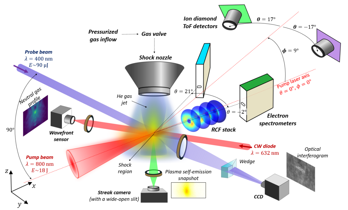
The experiment was performed at the Centro de Láseres Pulsados (CLPU) facility using the PW-class, ultrahigh-intensity (UHI) Ti:Sa VEGA-3 laser system. The experimental setup is depicted in Fig. 1.
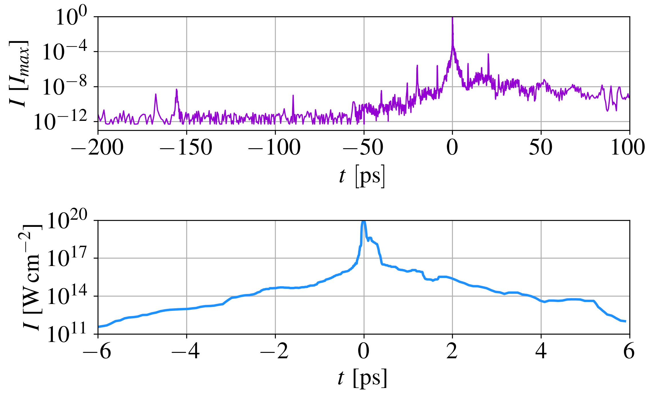
The wavelength laser pulse delivered an energy of on target. It had a full-width-at-half-maximum (FWHM) duration of (monitored on each shot) and was focused using an off-axis parabola to a FWHM spot size (monitored on a daily basis). These characteristics represent the mean and standard deviation values from more than 40 measurements taken during the campaign. The pulse energy is extrapolated from calibrations at low energy. The same energy level is also used to image the focal spot, which is assume invariant at high energy. A peak pulse intensity of was then inferred, corresponding to a normalized laser amplitude of . The laser contrast was measured to be up to prior to the intensity peak, and up to [see Fig. 2(a)].
The gas jet was produced by a so-called shock nozzle, consisting of a cylindrical Laval nozzle with an extra straight conduct added at its exit [51]. Upon bouncing off the latter, the converging hydrodynamic flow produces a peaked density profile along the laser propagation direction. Both the nozzle and gas valve were located near the target chamber center (TCC), their position being adjusted vertically to make the laser pulse interact with the shocked gas region. The high-pressure gas system comprised a SL-GT-10 gas compressor (with 400 bar backing pressure) and a gas valve, both commercialized by SourceLAB [52]. The valve was designed to avoid leakages in harsh UHI laser environments by means of a normally-closed opening system adapted to the millimeter-sized throat of the nozzle. Moreover, a security system [53] automatically closed the valves between the vacuum chambers to protect the laser transport pipes and vacuum components from strong pressure rises during UHI shots.
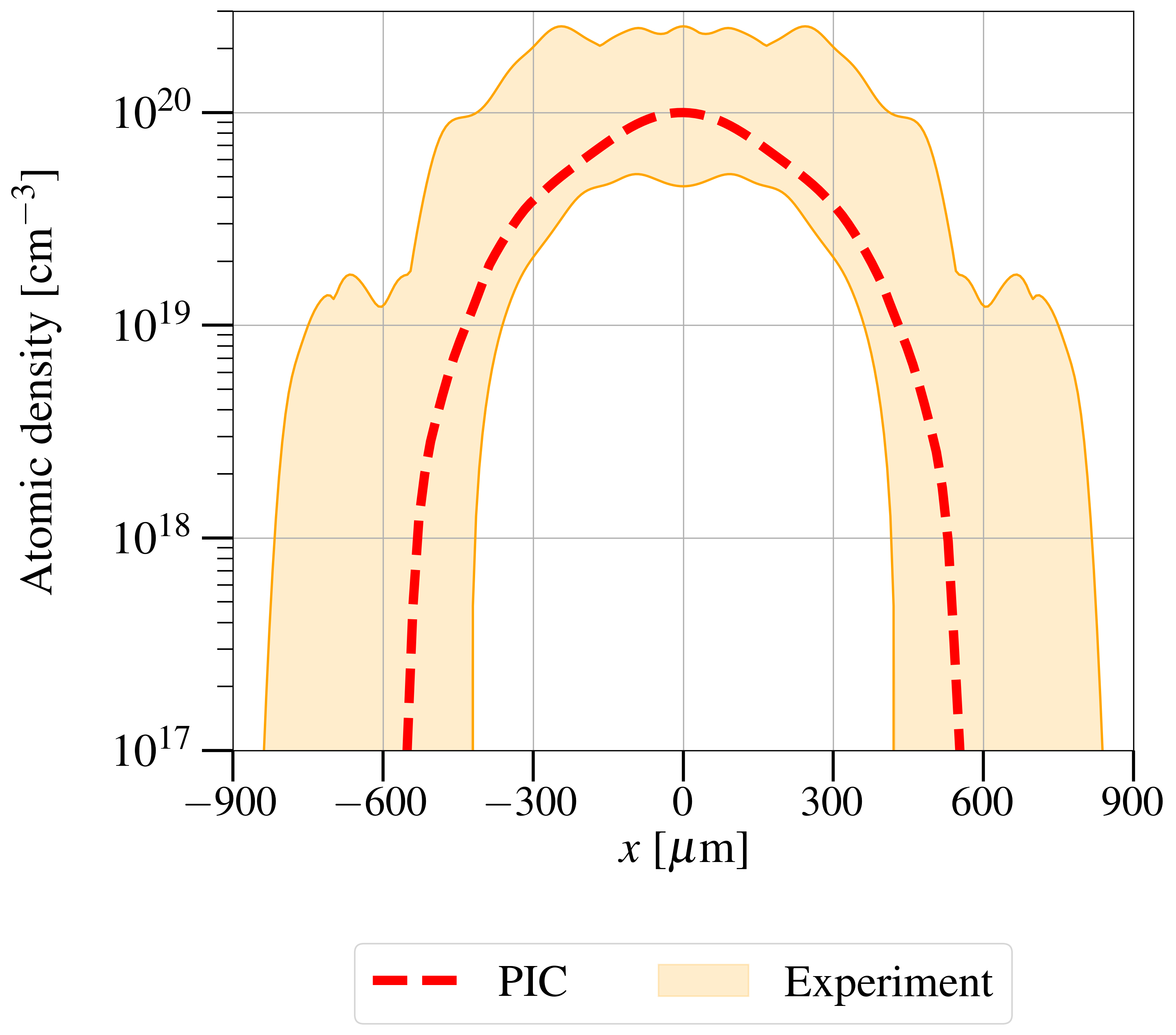
Two nozzle types were fielded, one provided by SourceLAB, the other developed within our collaboration group [54, 55]. Both were designed to produce shocked gas regions with sharp density gradients and located as far as possible from the nozzle to mitigate laser damage to the latter. However, albeit not severe enough to disrupt the laser-plasma interaction, such damage turned out to be significant enough to gradually smooth the density profiles (see orange shaded area in Fig. 4), which hence ended up looking similar to those achieved with Laval nozzles.
A wavefront sensor and a folding-wave interferometer [56, 57] allowed us to obtain two-dimensional profiles of, respectively, the pre-shot neutral gas atomic density and on-shot plasma electron density. The first diagnostic used a continuous He-Ne laser while the second used a probe beam (a pickoff of the pump beam) sent through TCC perpendicularly to the main laser’s path and at different temporal delays.
Optical self-emission images of the plasma, integrated over a time window, were also recorded using a Hamamatsu S20 streak camera operating in gate mode (with a wide-open slit), combined with a band-pass filter. The same imaging system was connected to a charged coupled device (CCD) camera to monitor the nozzle position between shots and adjust it if needed. The laser axis was controlled separately by imaging the defocused beam after TCC along the expected axis.
The particle diagnostic suite included two diamond time-of-flight (ToF) detectors [58, 59, 23] placed on the chamber flanges, at angles and relative to the laser axis, as defined in Fig. 1 (negative values correspond to clockwise rotation as seen from top view). In addition, two magnet electron spectrometers (MES) [60] were positioned at and . Both ToF [59] and MES [60] systems were fully calibrated. Moreover, to characterize the transverse profile of the accelerated particles on some shots, a stack of radiochromic films (RCF) was placed from TCC, normally to the laser axis. It was composed of a thick aluminum foil followed by five unlaminated EBT-3 films and ten standard EBT-3 Gafchromic dosimetric films. Each layer had a 4 cm diameter exposed surface. A motorized holder allowed several shots to be performed in a row without opening the vacuum chamber. Finally, on some shots, an angle-resolved Thomson parabola (TP) [61], coupled with a Fuji BAS-TR imaging plate, was fielded on axis at from TCC, with three horizontally aligned, diameter pinholes at its entrance. These were spaced apart to capture ion spectra at and . A manual extraction system allowed the IPs to be replaced between shots without breaking vacuum. All those diagnostics were successfully tested on laser-solid shots (using thick aluminium foil targets) [62], before moving on to laser-gas shots.
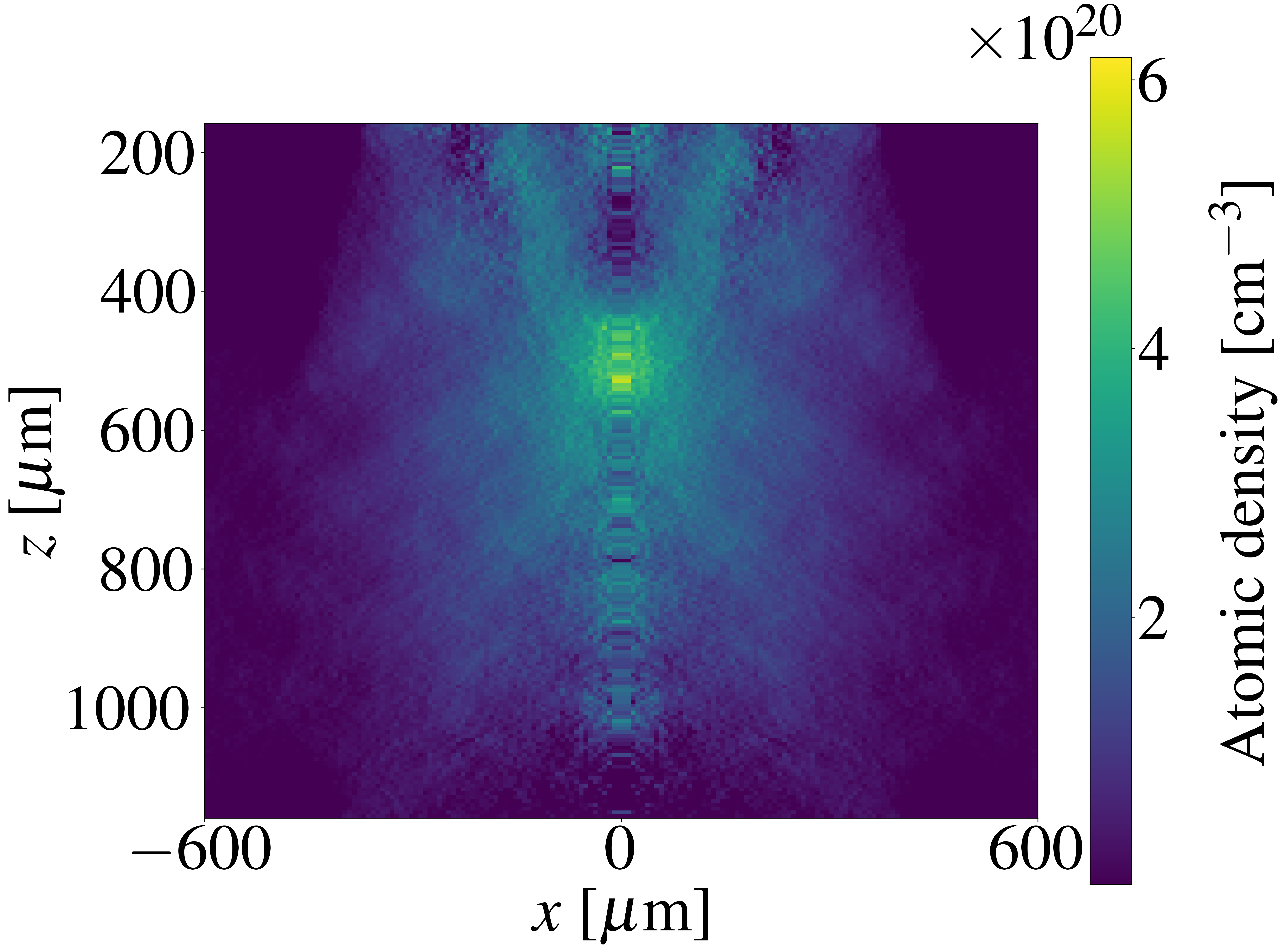
In the following, we will examine the experimental results from five shots on a He gas jet. Figure 3 displays a typical atomic density map of the pre-shot neutral gas jet while Fig. 4 shows (as an orange shaded area) the range of the atomic density profiles recovered along the laser path. Maximum atomic densities of , corresponding to maximum electron densities of at full ionization, were achieved with a FWHM. The two shock nozzle types that were used delivered similar gas profiles. Shot-to-shot variations due to laser-induced nozzle damage were mitigated by adjusting the vertical () position of the shocked region before each UHI shot [62]. Nevertheless, after a couple of shots, one observed the appearance of low-density () spatial “elbows” (shaded areas beyond in Fig. 4). The non-damaged nozzle profiles were similar to the one (red dashed curve) used as input to the PIC simulations. The laser pulse was focused either to the TCC, where the gas density peak (GDP) was located, or in front of it so as to weaken laser self-focusing and filamentation [63].
III PIC simulation setup
Before discussing the experimental data, we detail the two PIC simulations performed to interpret them. These simulations, conducted in 2D3V geometry (two-dimensional in configuration space and three-dimensional in momentum space) using the fully relativistic and electromagnetic PIC calder code [64, 65], describe the interaction of a wavelength laser pulse with peak intensity and FWHM focal spot. This pulse is linearly polarized along the -axis and injected along from the left-hand side () of the simulation box. In the reference simulation, the vacuum focal plane is located in front of the GDP, as in the shots corresponding to the particle spectra reported below. The temporal laser intensity profile, extracted from an experimental measurement, is shown in Fig. 2(b). It comprises a -long, low-intensity () up-ramp, a main pulse and a -long, low-intensity down-ramp. In order to assess possible laser filamentation effects, a second simulation was performed with the same setup, but with the laser focal plane located at the GDP.
The simulation domain, of dimensions , is discretized into cells with a mesh size of . The time step is set to . The density profile of the initially neutral He gas is taken to be uniform along the transverse () direction. Its longitudinal (along ) profile is extracted from experimental data (see red dashed curve in Fig. 4) and extrapolated below (the minimum measurable density value) down to . The GDP is located at in the simulation box. Owing to their computational cost, our simulations are restricted to specific density conditions. As the shot-to-shot variations in the gas profile displayed in Fig. 4 did not profoundly alter the experimental characteristics of the particle spectra or the bulk gas behavior, we are confident that the simulation setup captures well the relevant interaction physics.
The gas is initially represented by two macro-atoms per cell and its temperature is set to a low () value. Electron impact [66] and field-induced [67] ionization processes are taken into account together with Coulomb collisions between all charged particles. Absorbing boundary conditions are applied for both fields and particles in all directions.
Each simulation was run on cores during 72 hours, for a total number of time steps, corresponding to physical time.
IV Experimental results and discussion
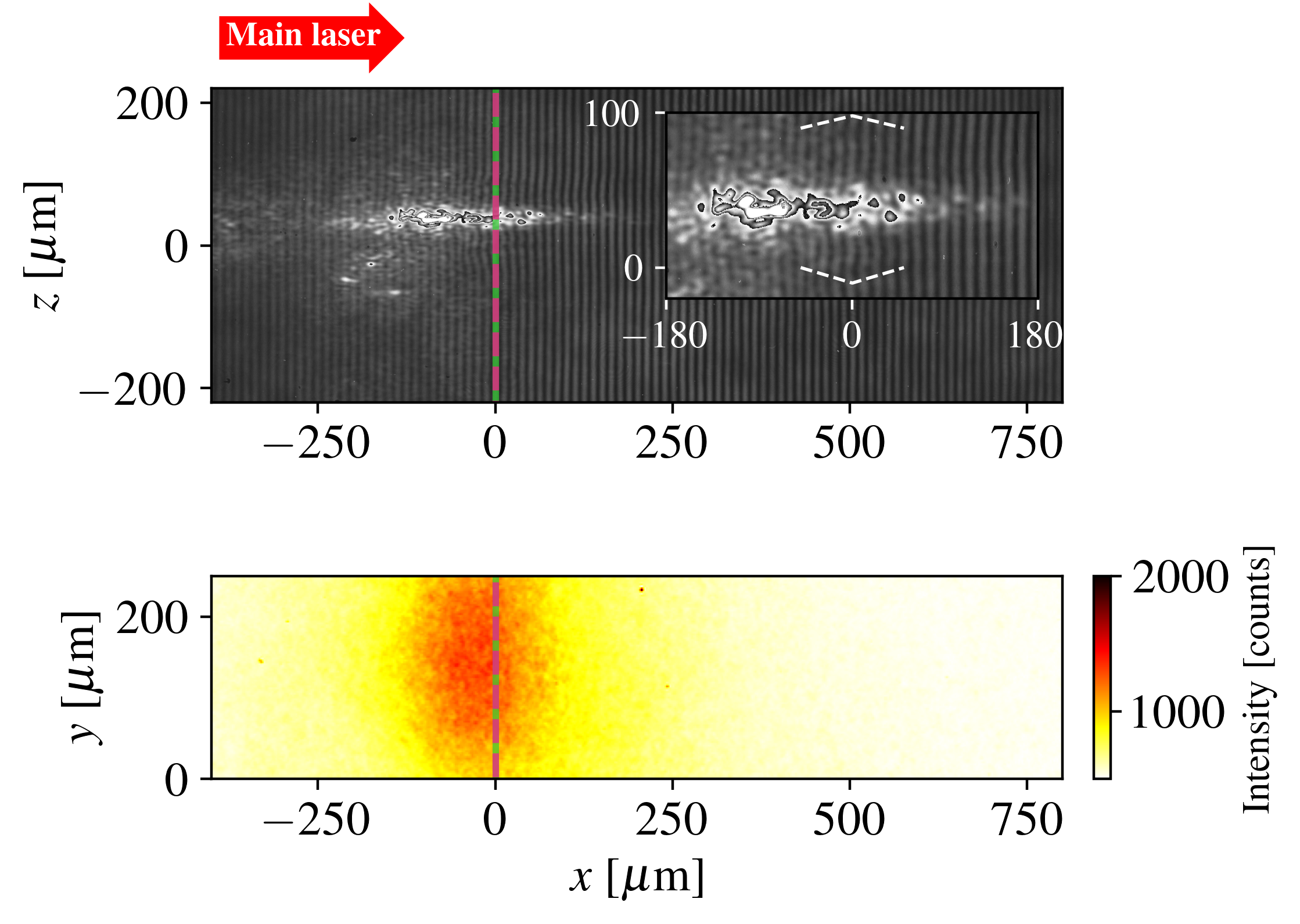
Let us first examine the bulk response of the ionized gas jet to the laser drive. Figure 5(a) shows a raw interferogram recorded after the arrival of the UHI pulse to the GDP. The green solid and pink dashed lines mark the locations of the focal plane and GDP, respectively. One cannot discern the fringes around the laser path () at a distance less than from the GDP (here located at ) due to intense plasma self-emission (integrated over the millisecond exposure time of the CCD imaging the fringe pattern). This observation suggests strong laser-gas coupling, as confirmed by the time-integrated plasma image of Fig. 5(b) which reveals bright optical emission within a long region encompassing the GDP. Fringe displacement, however, is visible in Fig. 5(a) a few off axis (as indicated by the dashed white curves in the inset), evidencing formation of a plasma (the borders of which are marked by dashed lines) around the bright laser channel.
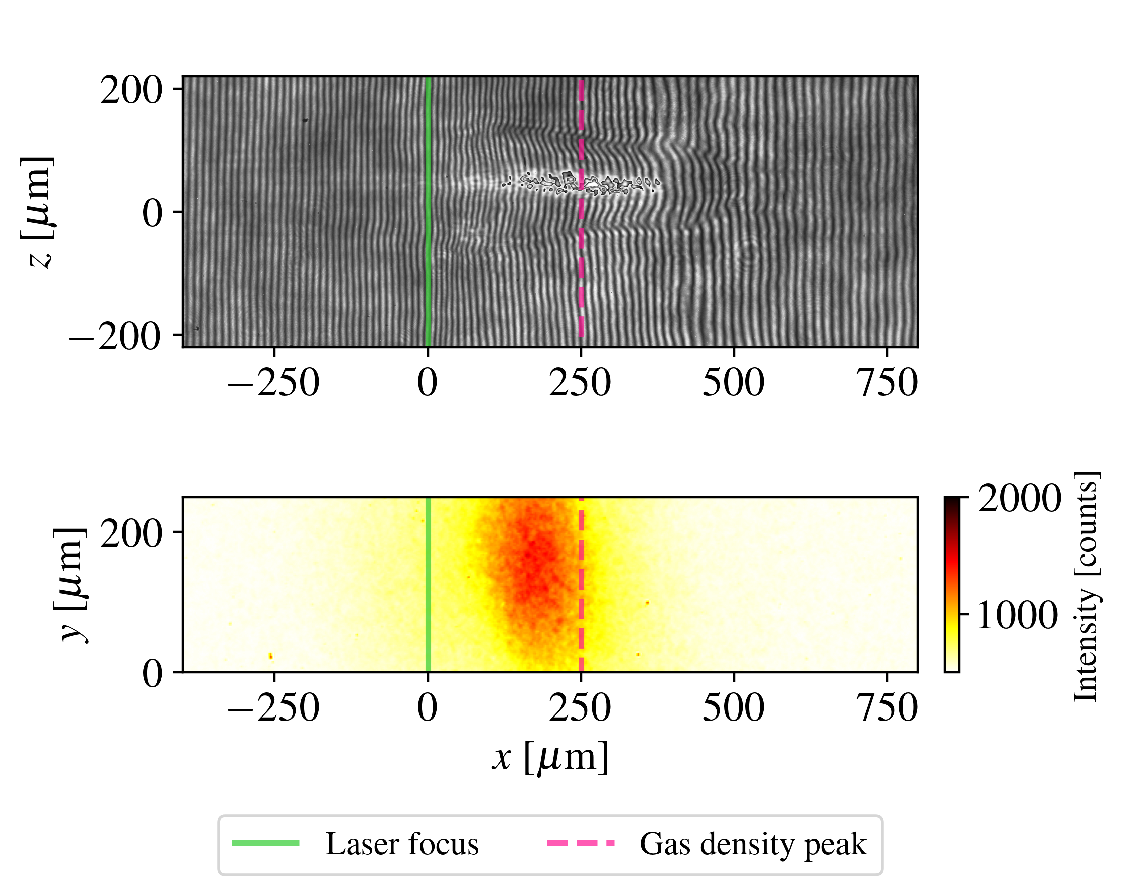
Figure 5(c) shows an interferogram taken at a later time ( after the laser maximum), in the case where the laser is focused before the GDP. Fringes are clearly displaced in a length, radius region extending across the GDP, as a result of plasma expulsion from the laser path (see below). The plasma self-emission is then most intense in a -long region of the gas up-ramp nearing the GDP.
It should be realized that the interferometric patterns in Figs. 5(a) and (c) correspond to snapshots of the plasma with a temporal resolution given by the probe beam duration. Note further that the 180 ps integration time (starting at the laser pulse’s arrival time) of the plasma images in Figs. 5(b) and (d) is likely much larger than the timescale of intense plasma self-emission, ascribed to nonlinear spectral broadening of the scattered laser light [68].
It did not prove possible to reconstruct the free electron density distribution from the early-time interferogram of Fig. 5(a) because of too intense plasma emission in the vicinity of the laser path. In the later-time interferogram of Fig. 5(c), by contrast, the plasma channel has radially expanded outside the brightest emission zone, allowing the fringe pattern to be deconvolved in the region of interest.
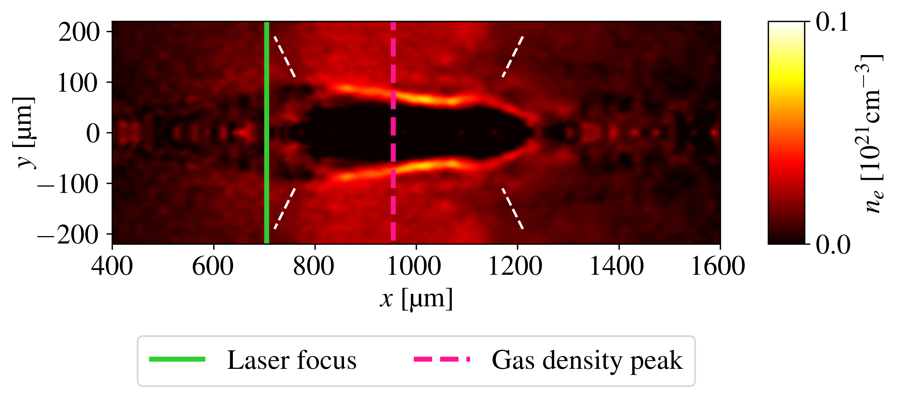
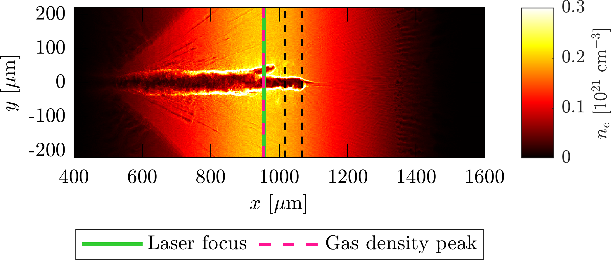
The retrieved electron density distribution is shown in Fig. 6(b). As was guessed from the raw interferogram, one clearly sees an electron-depleted channel, extending longitudinally across the GDP (pink dashed curve) over a total length and radially from the laser axis. The white dashed lines serve to guide the eye along outward “wings”, namely, artifacts resulting from the cylindrical symmetry around the axis assumed when Abel inverting the phase map deduced from the interferogram. Yet this assumption is only approximate as it conflicts with the normally directed gas flow. Note that in Fig. 6(b) the -ordinate of the original interferogram has been changed to (the reconstructed density profiles along and being supposed identical) for consistency with the coordinates used in the PIC simulation.
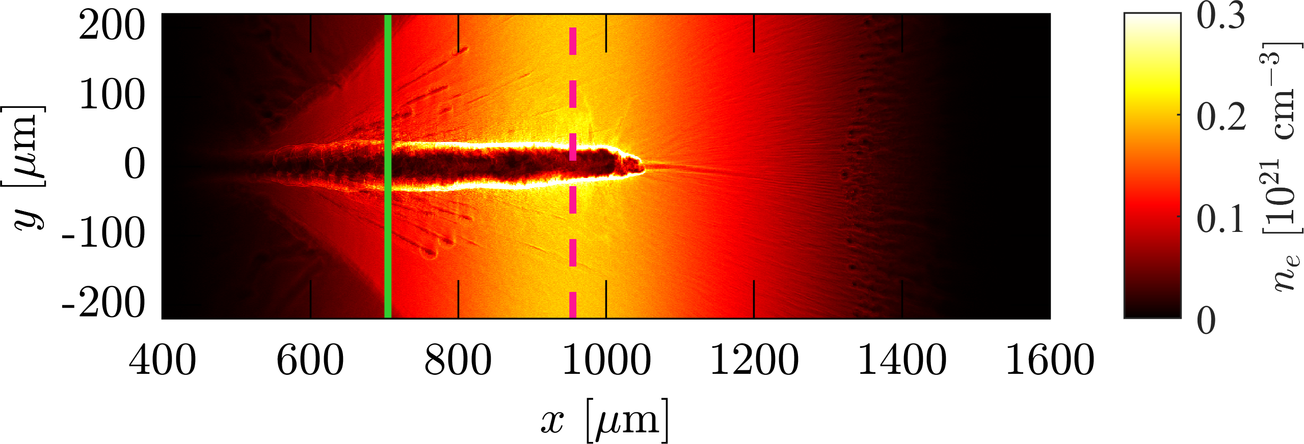
For qualitative comparison, we display in Fig. 6(a) the electron density map predicted by the reference PIC simulation after the laser pulse maximum reached the GDP (pink dashed line). Fair agreement is found between the simulated and measured plasma channels: they share about the same () length and both extend across the GDP. The simulated channel, though, forms earlier in the gas up-ramp and terminates at a shorter depth in the gas down-ramp, where the laser pulse ends up being fully absorbed. Moreover, as expected given the earlier time of probing considered, the channel has expanded over a shorter transverse distance ( vs ) than observed in the experiment at . Note that the reduced 2D geometry of the simulation may also affect the late-time transverse dynamics of the channel [69, 70]. Furthermore, the He gas has been fully ionized over most of the simulation domain as a result of field and impact ionization by the laser-accelerated electrons spraying from the channel. The diverging envelope of the electron density distribution in the gas up-ramp visualizes the emission cone of the ionizing fast electrons from the plasma channel.
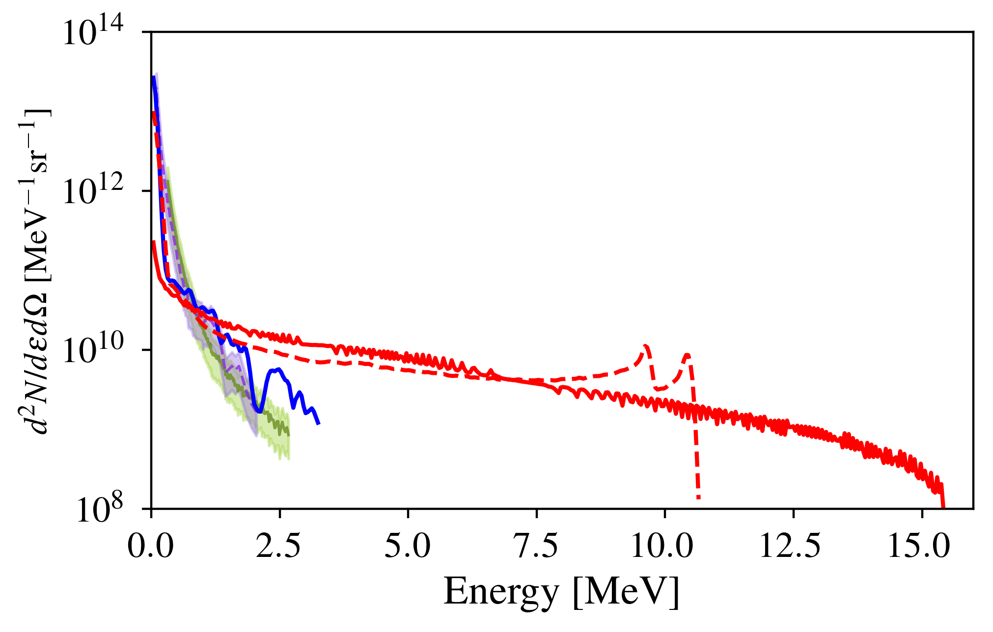
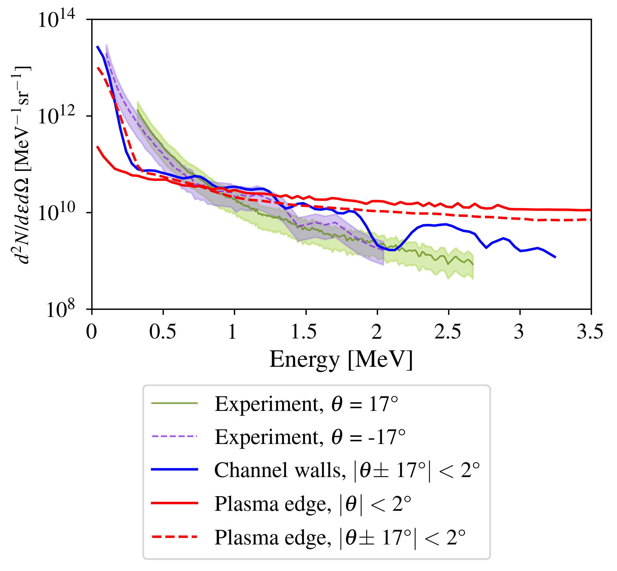
Significant ion acceleration was detected by the two ToF diamond detectors fielded at relative to the laser axis, with a collection solid angle of . Figure 7 plots (as green solid and purple dashed curves) the (He2+) particle spectra inferred via the method detailed in Refs. [59, 23]. Similar spectra were detected on the two channels. They extend up to with a total flux of , as integrated over energies and seen within the solid angle of the detectors. In the range, the energy-differential flux varies between and , while it reaches around the lower detection limit (). Although ToF detectors cannot differentiate between charged species, we are confident that the measured spectra are mainly associated with He2+ (even though a minor contribution of He+ ions due to recombination cannot be strictly ruled out). Our PIC simulations indeed indicate that the gas is fully ionized where ion acceleration mainly takes place (see below) and that there is no energetic ions in the experimentally detected emission cone. It should also be stressed that the two spectra reported in Fig. 7 were acquired on different shots. No simultaneous ion signals on the two ToF detectors could indeed be recorded during the campaign, suggesting strongly anisotropic ion emissions. Moreover, on the TP-dedicated shots, no ion signal was retrieved on the exposed IP; only the three zero-deflection points imprinted by the x rays coming from the interaction zone were visible.

Figure 8(a) shows the raw ToF data associated with the spectrum plotted (in purple) in Figs. 7(a) and 7(b). The abscissa corresponds to the time of arrival of the particles to the detector while the ordinate represents the signal voltage, proportional to the collected particle charge. The red arrow points to the signal due to x rays that first reach the detector. This so-called photopeak marks the origin of time and allows the subsequent ion-induced signal to be deconvolved [59, 23]. In Fig. 8(b) the abscissa has been converted into energy knowing the particle mass and distance traveled. Notice how the signal in Fig. 8(b) already reproduces the spectral shape seen in Fig. 7(b), where the detector’s calibration was used to obtain absolute particle numbers.
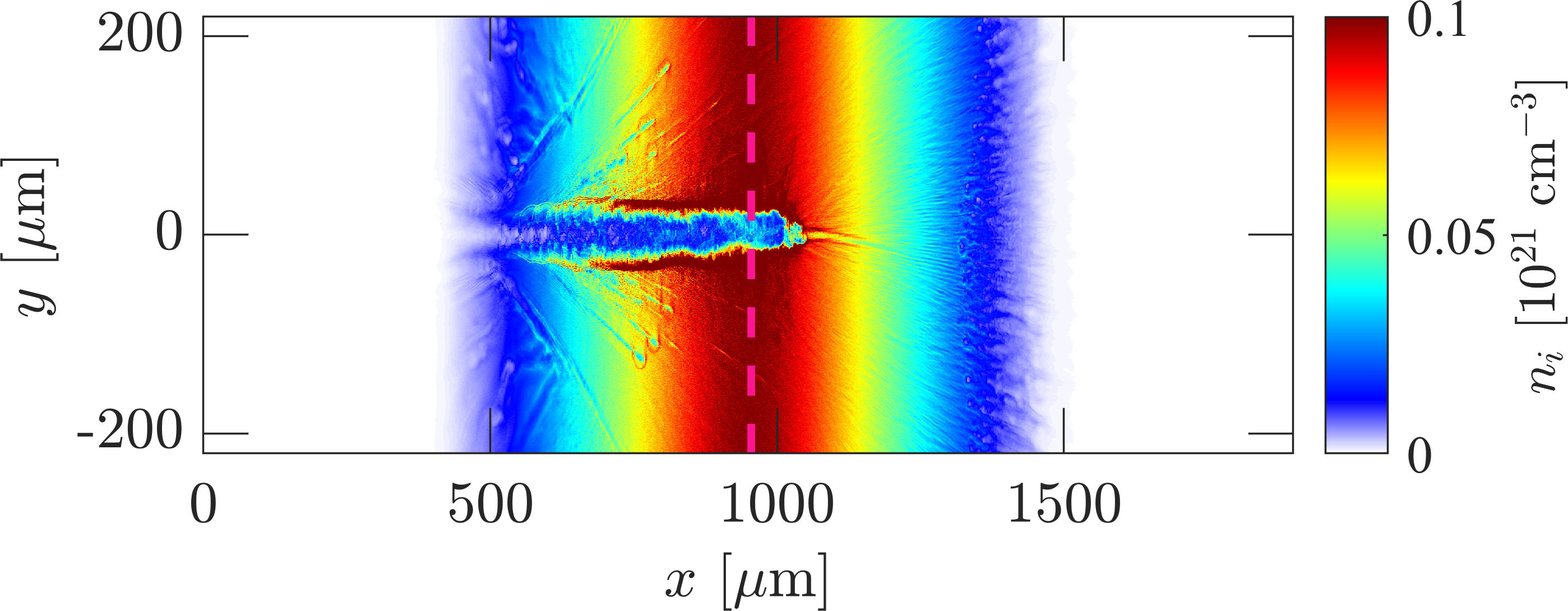
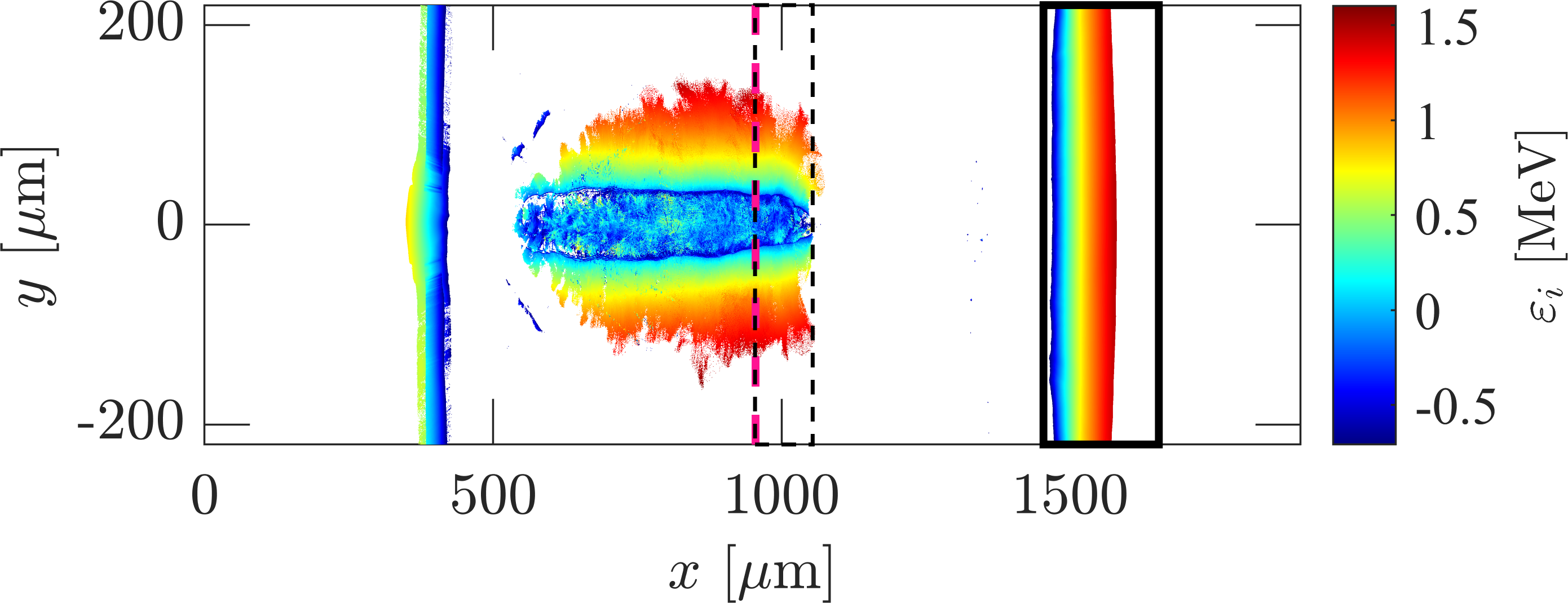

To explain the origin of the detected MeV-range particles, we present in Figs. 9(a)-(e) various phase-space projections of the simulated He ion distribution. Figure 9(a) shows the spatial ion density distribution at the final simulation time ( after the laser pulse has crossed the GDP) and, notably, the ion depletion within the plasma channel already depicted in Fig. 6(a) through the electron density distribution.
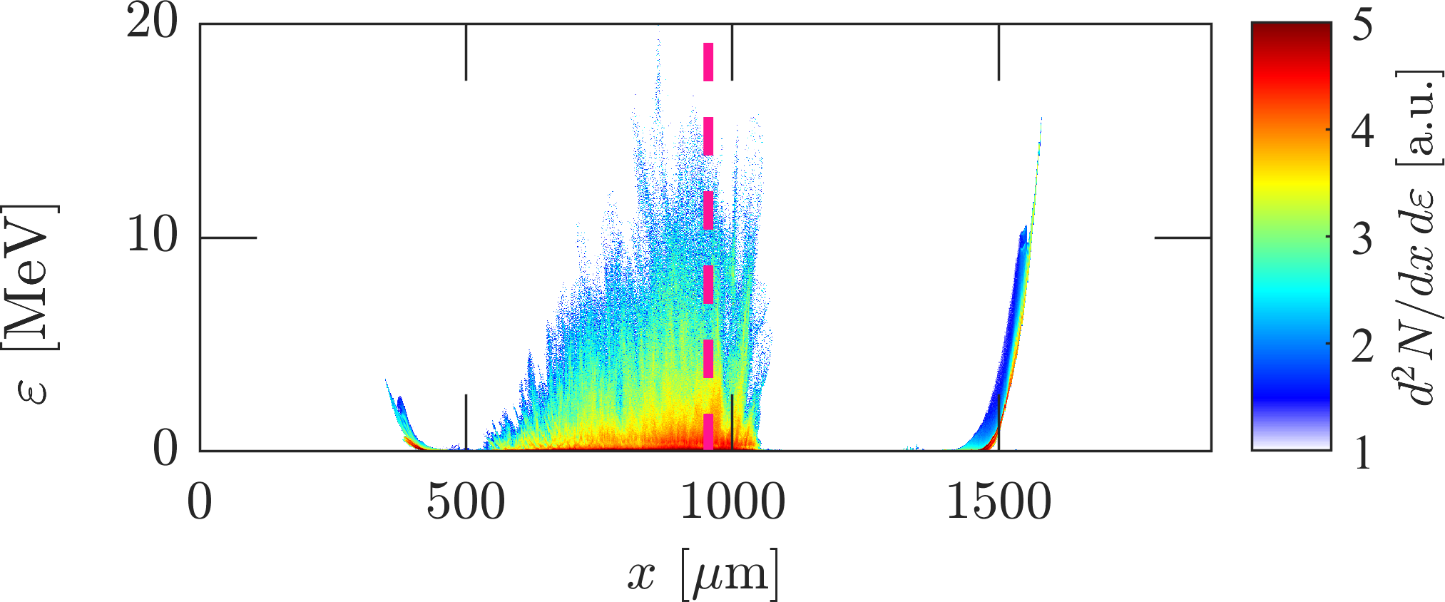
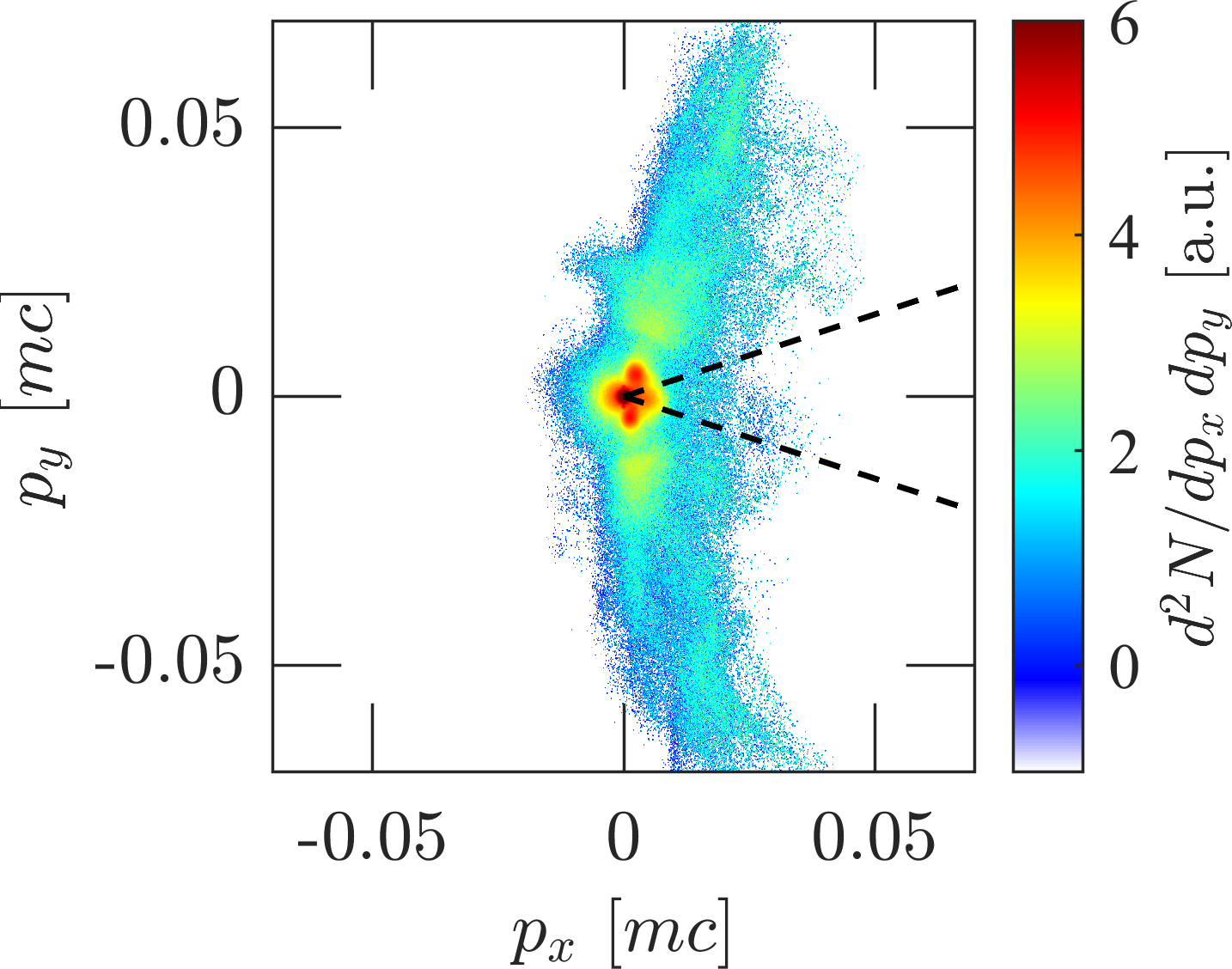
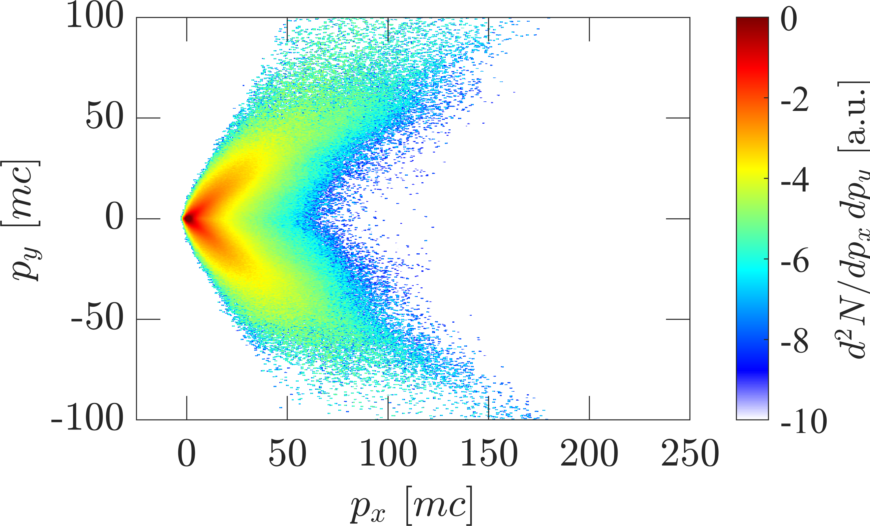
Figures 9(b) and 9(c), which depict, respectively, the spatial distribution of the mean ion kinetic energy and the -resolved ion energy distribution, reveal three main sites of ion acceleration. The first is located at the (mainly) transversely expanding walls of the laser-drilled channel, where electrostatic ion reflection can occur as reported in Ref. [46]. Maximum ion energies of are found in this region. While most of the ions swept up by the channel are reflected at near-normal angles, those located in the vicinity of the channel’s head [see dashed box in Fig. 9(b)] are accelerated over a broad forward-directed cone. Their momentum distribution, displayed in Fig. 9(d), appears to be highly anisotropic, with the fastest () ions propagating at from the laser propagation direction
To illustrate the channel reflection mechanism, Fig. 10(a) shows the free electron density distribution, extracted after the laser pulse has reached the GDP, from the PIC simulation using a laser pulse focused at the GDP. Two distinct laser-driven channels are now visible as a consequence of laser filamentation. This contrasts with the single channel observed in the previous simulation, where the pulse was focused before the GDP [Fig. 6(a)]. The ion acceleration associated with the transverse expansion of the main channel is evidenced in Fig. 10(b), which displays the ion phase space around the right end of the channel [dashed black box in Fig. 10(a)]. A close examination shows that the ions reflected (up to ) off the expanding channel boundaries () subsequently experience TNSA-type acceleration in the charge-separation field set up by the hot electrons outside of the channel. This leads to maximum transverse velocities of (corresponding to energies) at the time considered.
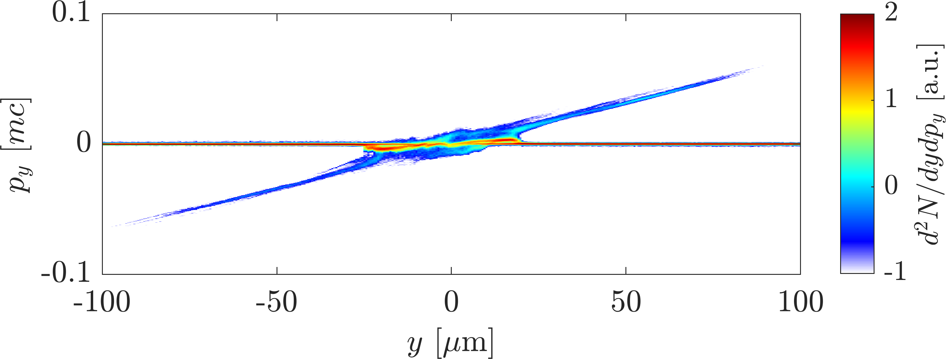
Figures 9(b) and (c) disclose two other potential sources of energetic ions, namely, at the left- and right-hand boundaries of the gas profile ( and ), where TNSA sets in following the arrival of the laser-generated relativistic electrons. The ions accelerated via this process (most efficient at the right border of the gas profile) are predicted to reach about the same maximum energies as the ions reflected from the channel walls, but with a more collimated angular distribution [see Fig. 9(e) corresponding to the solid black box in Fig. 9(b)]. The fastest () “TNSA ions” are contained in a very narrow cone (), yet a dilute halo of quite energetic () ions propagating at much larger angles () can also be seen. These divergent ions, which could, in principle, be collected by the ToF detectors, originate from deflections in the strong (as high as ) transverse magnetic fields induced at the rear edge of the gas, as shown in Fig. 11. This figure displays the spatial distribution of the out-of-plane () magnetic field after the laser pulse has reached the GDP. The laser pulse has then been fully absorbed in the gas down-ramp, as evidenced by the relatively short longitudinal extent of the magnetized plasma channel past the GDP. The strong fields that have developed at the plasma backside are ascribed to both the fountain-type motion of the fast electrons exiting the gas [71] – which induces coherent fields of opposite polarity across the symmetry -axis – and the unstable interpenetration of the exiting and space-charge-reflected electron streams [72, 73, 74, 75] – which induces transverse field modulations with a wavelength increasing at lower densities.
An ion of mass , charge , longitudinal velocity and energy travelling across a magnetic field of amplitude and longitudinal extent will undergo a transverse deflection in the weak-deflection limit. Taking and as typical values (see Fig. 11), one thus expects deflection angles of for He2+ ions, roughly consistent with the angular spread seen in Fig. 9(e).

The maximum energies predicted to be reached by the TNSA ions along the lines of sight of the ToF detectors are, however, inconsistent with the experimentally inferred cutoff energy (Fig. 7). Worse, the dominant highly collimated component of those ions should have been detected by the TP fielded on axis on some shots. These discrepancies, therefore, cast serious doubt on the effective operation of the TNSA mechanism in the experiment. It is indeed well known [76, 77] that the efficiency of TNSA is sensitive to the shape of the plasma profile where the sheath field develops, i.e., the outer region where the background electron density becomes lower than the local hot-electron density or where the local Debye length becomes larger than the density scale length.
Thus, the absolute value of the hot-electron density not only controls the accelerating field strength but also the position of the acceleration site. Here, owing to a gas profile truncated below (the lower bound of the detectable gas density) and a likely overestimated hot-electron density (due to the 2D geometry considered) at the remote gas edge, away from the plasma channel where most of the hot-electron generation takes place, one may expect TNSA to be greatly enhanced in the simulation compared to what occurs in the experiment. Likewise, the fields induced by the fast-electron currents in the TNSA region are very likely overestimated. By contrast, the numerical modeling of the channel-expansion-induced ion acceleration should be more reliable because this process operates in the vicinity of the laser path, because our simulation captures fairly well the shape of this channel and, finally, because the foreseen cutoff energies associated with this mechanism compare rather well with the measurements.
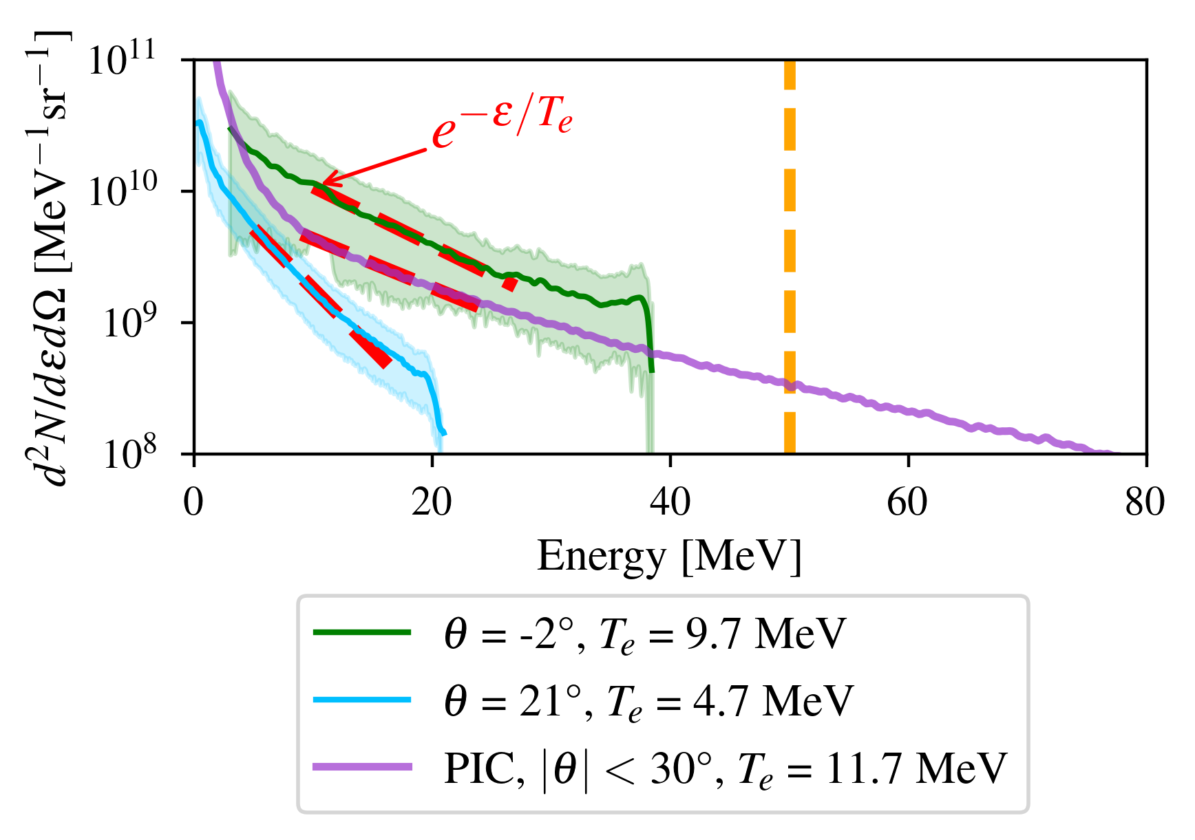
We now discuss the electron acceleration measurements. Figure 12 plots representative electron spectra collected by the MES fielded on axis () and off axis (). The error bars are computed over three different shots. The vertical dashed line indicates the upper detection limit. The typical spectra recorded at (green curve) exhibit a quasi-exponential shape, decreasing from at down to at the cutoff energy. Assuming those spectra scale as , this corresponds to a best-fitting “temperature” of , i.e., about larger than the standard ponderomotive scaling [43] . This trend qualitatively agrees with previous related numerical studies [78, 65, 79].
The typical electron spectra recorded at from the laser axis are plotted in light blue in Fig. 12. Their significantly lower temperature () and energy cutoff () give a measure of the directionality of the fast electrons exiting the plasma. The purple curve represents the simulated electron spectrum, integrated over a angular range (corresponding to the full forward-emission “cone” of the hot electrons in the simulation). Its quasi exponential shape with temperature is consistent with the measurements.
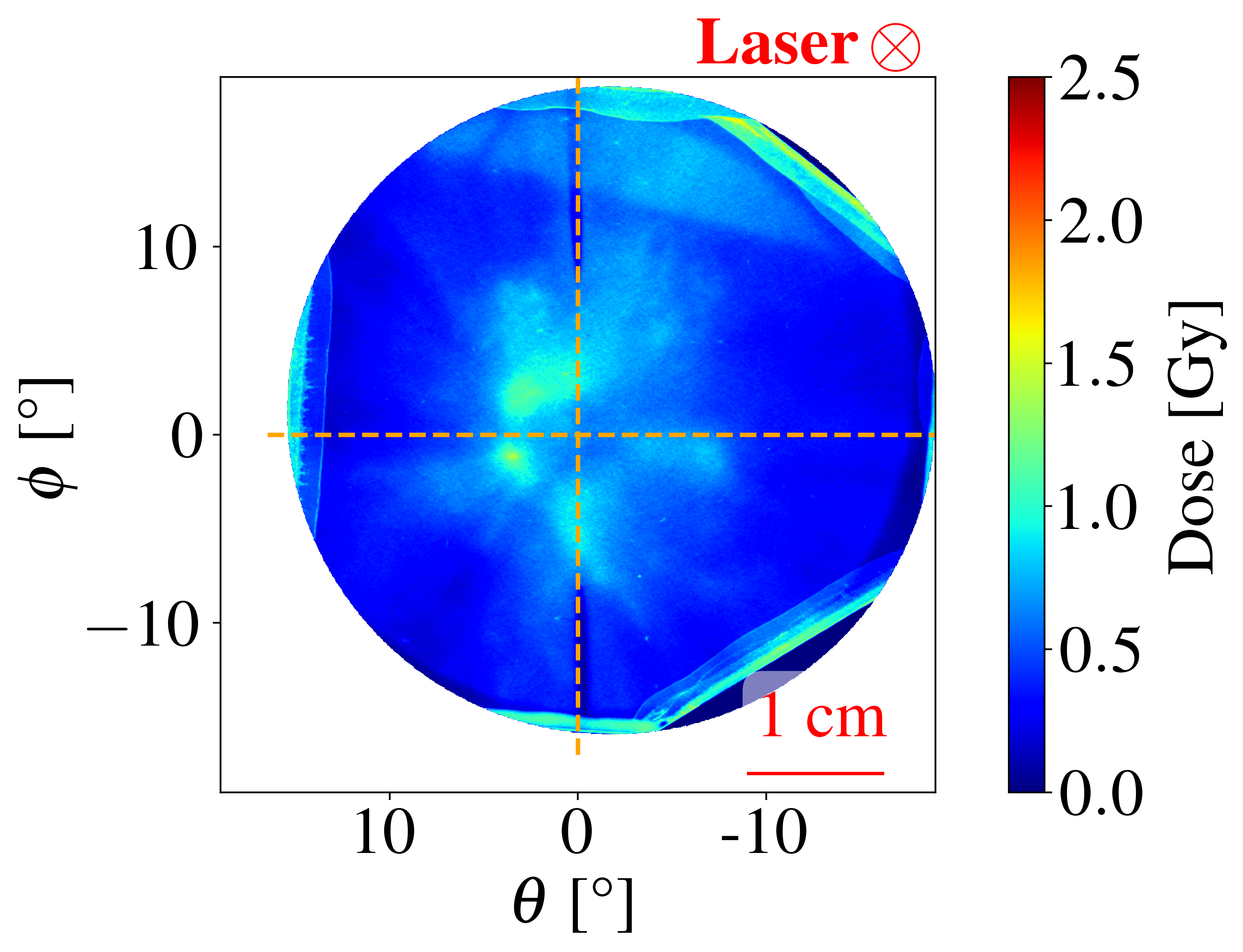
The angular distribution of the outgoing fast electrons can be further assessed from the RCF data. Indeed, given the cutoff ion energies inferred from the ToF data and the absence of ion signal on the on-axis TP, one can predict through Monte Carlo simulations performed with PySTarT [80] (a python wrapper for the srim package [81]) that the emitted ions will be fully stopped by the second RCF stack layer, and hence that the dose deposited on subsequent layers is essentially due to fast electrons. The spatial dose distributions measured deep (beyond the 10th layer) inside the RCF stack typically exhibit several hot spots, as illustrated in Fig. 13(a). The signal shown was recorded on the deepest (15th) layer (mainly sensitive to electrons according to geant4 [82] Monte Carlo modeling) during a single shot (not associated with the electron spectra shown in Fig. 12, as the MES and RCF stack could not be fielded simultaneously). The dose is mainly deposited over a FWHM cone, with several hot spots surrounding the laser axis (center of dashed cross), corresponding to electron beamlets emitted at a few () degrees. This suggests that the MES located at and may miss the dominant components of the outgoing energetic electron population. An estimate of the outgoing electron charge can be obtained from the electron spectrum in green in Fig. 12 considering the dose-deposition spot centered at in the RCF layer depicted in Fig. 13(a). The typical outgoing charge above is corresponding to , i.e., of the laser drive energy.
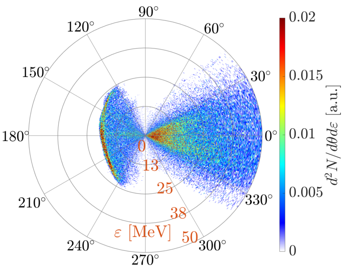
We display in Fig. 13(b) the energy-angle distribution of the fast electrons having reached the “plane” in the PIC simulation. The backward-directed part of this distribution corresponds to the electrons reflected by the TNSA field. The purpose of this numerical diagnostic is to compare the angular distribution of the outgoing energetic electrons with that inferred from the RCF signals. The angular distribution of the fast electrons is quite inhomogeneous and mainly contained in the range.
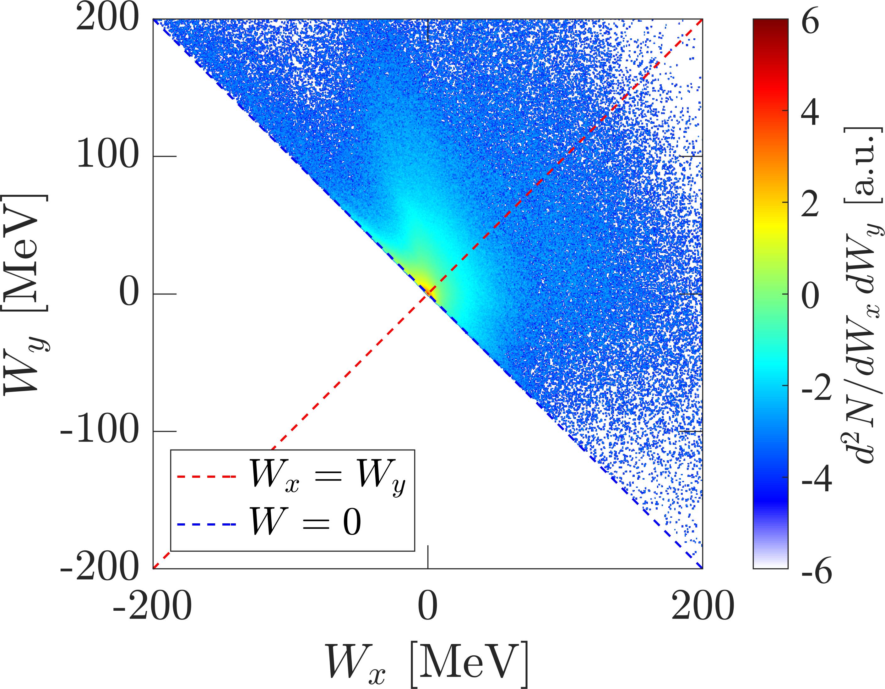
To identify the dominant electron acceleration mechanism, we plot in Fig. 14(a) the electron distribution resolved as a function of the works performed by the longitudinal () and transverse () electric fields defined as . This diagnostic is extracted before the laser pulse has reached the GDP. Since all plasma electrons have gained energy from the laser, we have , which explains the sharp linear lower boundary of the distribution. The laser-accelerated electrons are then mainly concentrated around the head of the laser-created plasma channel, located around . Importantly, a significant majority of them satisfy ; this means that they have been mainly energized by transverse fields – largely dominated by the laser field – rather than by longitudinal, laser-wakefield-type fields, a process known as direct laser acceleration (DLA) [47, 49, *Shaw_2018, 48].
Figure 14(b) shows the momentum distribution of the energetic electrons outgoing from the plasma channel and then lying in the spatial range (in the gas down-ramp), after the laser pulse has crossed the GDP. The forked shape of this distribution is typical of DLA.
V Conclusions
Here, we have presented the results of an experiment in which we coupled a , laser pulse to a near-critical He gas jet, and probed the interaction region with an extensive diagnostic suite. Our main findings are (i) the acceleration at forward oblique angles () of particles up to energies () with a total flux of above energies; (ii) the emission of a quasi-exponential distribution of forward-directed hot electrons with a total charge and a temperature well above the ponderomotive scaling. To our knowledge, the only other experiment on particle acceleration in near-critical gas jets () driven by PW-class, ultrashort () laser pulses was reported by Singh et al. [46].
According to large-scale PIC modeling, the observed forward ion acceleration most likely arises from electrostatic reflection of the ions swept up by the radially expanding laser-induced plasma channel – the formation of which across the gas density peak was also evidenced via interferometry. The same collisionless-shock-based mechanism was held responsible for the transverse emission of H+ and He2+ ions in Ref. [46]. While this mechanism preferentially drives ions perpendicularly to the laser path [46], our simulations reveal that the ions initially located near the end of the channel, in the gas down-ramp, can be accelerated over a broad forward directed cone, including the lines of the sight of the ToF detectors, and to energies consistent with the measurements. The simulations also predict TNSA-type ion acceleration at the rear edge of the gas, as well as deflection of the lower-energy ions by the local magnetic fields. However, the high energies () reached by the fastest TNSA ions are not corroborated by the measurements. We ascribe this disagreement to an improper description of the fast-electron dilution far from the plasma channel and/or to a possibly too sharp truncation of the gas down-ramp. Furthermore, an experimental characterization of the gas-edge fields is needed to further assess the ion deflection scenario. Nevertheless, our modeling satisfactorily reproduces the quasi-exponential spectrum of the fast electrons and shows that they are primarily produced by the direct action of the laser’s electric field.
Finally, it is worth noting that, although our experimental suite was not fully adapted to HRR operation, we were able to achieve a frequency of one “UHI physics shot” every 20 minutes. This time was required to (i) obtain an interferogram of the pre-shot neutral gas, (ii) translate the nozzle vertically to have the laser interact with the shocked gas region, and (iii) perform two different acquisitions with the on-shot interferometry CCD (one with the probe only and another one with both gas and probe), which were needed to deconvolve the subsequent on-shot interferogram. Such a meticulous procedure was necessary to achieve well-controlled interaction conditions. We also leveraged this time to replace the passive particle detectors (i.e., the imaging plates and radiochromic films). In addition, we succeeded in performing up to four UHI laser shots in a row without the laser-induced nozzle damage severely altering the gas shape. Although the latter exhibited fluctuations in both peak density () and FWHM (), along with the formation of low-density () “elbows” after a certain degree of damage, such shot-to-shot variations remained moderate enough not tocompromise the typical properties of the accelerated particles or the bulk gas response to the laser drive.
Although very far from the ultimate goal of approaching the shot rate of modern Ti:Sa laser systems, these results represent, to our knowledge, the best performance ever reported using a PW-class Ti:Sa laser coupled with a dense gas jet. As such, they open up encouraging prospects for future applications requiring large statistics.
For instance, once the transverse size and emittance of the ion source have been characterized, high-precision stopping-power measurements [83] could be made. Compared to laser-based accelerators using solid targets, a prominent advantage of laser-gas setups would be the ability to deliver fast ions of any chemical element simply by changing the gas composition. The case of particles, as considered in this work, would be of particular interest for accurate predictions of the performance of inertial confinement fusion designs [84, *Zylstra_2022], a topic with far-reaching implications given the fusion breakthroughs reported at the National Ignition Facility in December 2022 and July 2023.
VI Acknowledgments
Thanks are due to R. Nuter for useful discussions. We received financial support from the French State, managed by the French National Research Agency (ANR) in the frame of the Investments for the future Programme IdEx Bordeaux - LAPHIA (ANR-10-IDEX-03-02). This work has received funding from the European Union’s Horizon 2020 research and innovation programs: Laserlab V (grant agreement No. 871124 INFRAIA and Joint Research Activity 2.4), IMPULSE (grant agreement No. 871161 INFRADEV). V. O-B and C. V. acknowledge the support from the LIGHT S&T Graduate Program (PIA3 Investment for the Future Program, ANR-17-EURE-0027). We acknowledge GENCI for providing us access to the Joliot-Curie supercomputer (grants 2021-A0130512993 and 2022-A0130512993). This scientific paper is published as part of the international project called “PMW”, co-financed by the Polish Ministry of Science and Higher Education within the framework of the scientific financial resources for 2021-2022 under the contract no 5205/CELIA/2021/0 (project CNRS No. 239915). This work has also been supported by the Research Grant No. PID2019-108764RB-I00 from the Spanish Ministry of Science and Innovation and from the Unidad de Investigación Consolidada de Castilla y León No. CLP087U16.
Data Availability Statement
The data that support the findings of this study are available from the corresponding authors upon reasonable request.
References
- Daido et al. [2012] H. Daido, M. Nishiuchi, and A. S. Pirozhkov, Review of laser-driven ion sources and their applications, Rep. Prog. Phys. 75, 056401 (2012).
- Macchi et al. [2013] A. Macchi, M. Borghesi, and M. Passoni, Ion acceleration by superintense laser-plasma interaction, Rev. Mod. Phys. 85, 751 (2013).
- Schreiber et al. [2016] J. Schreiber, P. R. Bolton, and K. Parodi, Invited Review Article: “Hands-on” laser-driven ion acceleration: A primer for laser-driven source development and potential applications, Rev.Sci. Instrum. 87, 071101 (2016).
- Borghesi et al. [2003] M. Borghesi, A. Schiavi, D. H. Campbell, M. G. Haines, O. Willi, A. J. Mackinnon, P. Patel, M. Galimberti, and L. A. Gizzi, Proton imaging detection of transient electromagnetic fields in laser-plasma interactions (invited), Rev. Sci. Instrum. 74, 1688 (2003).
- Borghesi et al. [2004] M. Borghesi, A. J. MacKinnon, D. H. Campbell, D. G. Hicks, S. Kar, P. K. Patel, D. Price, L. Romagnani, A. Schiavi, and O. Willi, Multi-MeV Proton Source Investigations in Ultraintense Laser-Foil Interactions, Phys. Rev. Lett. 92, 055003 (2004).
- Santos et al. [2015] J. J. Santos, M. Bailly-Grandvaux, L. Giuffrida, P. Forestier-Colleoni, S. Fujioka, Z. Zhang, P. Korneev, R. Bouillaud, S. Dorard, D. Batani, M. Chevrot, J. E. Cross, R. Crowston, J.-L. Dubois, J. Gazave, G. Gregori, E. d’Humières, S. Hulin, K. Ishihara, S. Kojima, E. Loyez, J.-R. Marquès, A. Morace, P. Nicolaï, O. Peyrusse, A. Poyé, D. Raffestin, J. Ribolzi, M. Roth, G. Schaumann, F. Serres, V. T. Tikhonchuk, P. Vacar, and N. Woolsey, Laser-driven platform for generation and characterization of strong quasi-static magnetic fields, New J. Phys. 17, 083051 (2015).
- Ehret et al. [2023] M. Ehret, M. Bailly-Grandvaux, P. Korneev, J. I. Apiñaniz, C. Brabetz, A. Morace, P. Bradford, E. d’Humières, G. Schaumann, V. Bagnoud, S. Malko, K. Matveevskii, M. Roth, L. Volpe, N. C. Woolsey, and J. J. Santos, Guided electromagnetic discharge pulses driven by short intense laser pulses: Characterization and modeling, Phys. Plasmas 30, 013105 (2023).
- Patel et al. [2003] P. K. Patel, A. J. MacKinnon, M. H. Key, T. E. Cowan, M. E. Foord, M. Allen, D. F. Price, H. Ruhl, P. T. Springer, and R. Stephens, Isochoric Heating of Solid-Density Matter with an Ultrafast Proton Beam, Phys. Rev. Lett. 91, 125004 (2003).
- Roth et al. [2009] M. Roth, I. Alber, V. Bagnoud, C. R. D. Brown, R. Clarke, H. Daido, J. Fernandez, K. Flippo, S. Gaillard, C. Gauthier, M. Geissel, S. Glenzer, G. Gregori, M. Günther, K. Harres, R. Heathcote, A. Kritcher, N. Kugland, S. Le Pape, B. Li, M. Makita, J. Mithen, C. Niemann, F. Nürnberg, D. Offermann, A. Otten, A. Pelka, D. Riley, G. Schaumann, M. Schollmeier, J. Schütrumpf, M. Tampo, A. Tauschwitz, and A. Tauschwitz, Proton acceleration experiments and warm dense matter research using high power lasers, Plasma Phys. Control. Fusion 51, 124039 (2009).
- Mančić et al. [2010] A. Mančić, A. Lévy, M. Harmand, M. Nakatsutsumi, P. Antici, P. Audebert, P. Combis, S. Fourmaux, S. Mazevet, O. Peyrusse, V. Recoules, P. Renaudin, J. Robiche, F. Dorchies, and J. Fuchs, Picosecond short-range disordering in isochorically heated aluminum at solid density, Phys. Rev. Lett. 104, 035002 (2010).
- Roth et al. [2013] M. Roth, D. Jung, K. Falk, N. Guler, O. Deppert, M. Devlin, A. Favalli, J. Fernandez, D. Gautier, M. Geissel, R. Haight, C. E. Hamilton, B. M. Hegelich, R. P. Johnson, F. Merrill, G. Schaumann, K. Schoenberg, M. Schollmeier, T. Shimada, T. Taddeucci, J. L. Tybo, F. Wagner, S. A. Wender, C. H. Wilde, and G. A. Wurden, Bright laser-driven neutron source based on the relativistic transparency of solids, Phys. Rev. Lett. 110, 044802 (2013).
- Kleinschmidt et al. [2018] A. Kleinschmidt, V. Bagnoud, O. Deppert, A. Favalli, S. Frydrych, J. Hornung, D. Jahn, G. Schaumann, A. Tebartz, F. Wagner, G. Wurden, B. Zielbauer, and M. Roth, Intense, directed neutron beams from a laser-driven neutron source at PHELIX, Phys. Plasmas 25, 053101 (2018).
- Horný et al. [2022] V. Horný, S. N. Chen, X. Davoine, V. Lelasseux, L. Gremillet, and J. Fuchs, High-flux neutron generation by laser-accelerated ions from single- and double-layer targets, Sci. Rep. 12, 19767 (2022).
- Spencer et al. [2001] I. Spencer, K. W. D. Ledingham, R. P. Singhal, T. McCanny, P. McKenna, E. L. Clark, K. Krushelnick, M. Zepf, F. N. Beg, M. Tatarakis, A. E. Dangor, P. A. Norreys, R. J. Clarke, R. M. Allott, and I. N. Ross, Laser generation of proton beams for the production of short-lived positron emitting radioisotopes, Nucl. Instrum. Methods Phys. Res. B 183, 449 (2001).
- Fritzler et al. [2003] S. Fritzler, V. Malka, G. Grillon, J. P. Rousseau, F. Burgy, E. Lefebvre, E. d’Humières, P. McKenna, and K. W. D. Ledingham, Proton beams generated with high-intensity lasers: Applications to medical isotope production, Appl. Phys. Lett. 83, 3039 (2003).
- Ledingham et al. [2014] K. W. D. Ledingham, P. R. Bolton, N. Shikazono, and C.-M. C. Ma, Towards laser driven hadron cancer radiotherapy: A review of progress, Appl. Sci. 4, 402 (2014).
- Cowan et al. [2004] T. E. Cowan, J. Fuchs, H. Ruhl, A. Kemp, P. Audebert, M. Roth, R. Stephens, I. Barton, A. Blazevic, E. Brambrink, J. Cobble, J. Fernández, J.-C. Gauthier, M. Geissel, M. Hegelich, J. Kaae, S. Karsch, G. P. Le Sage, S. Letzring, M. Manclossi, S. Meyroneinc, A. Newkirk, H. Pépin, and N. Renard-LeGalloudec, Ultralow emittance, multi-mev proton beams from a laser virtual-cathode plasma accelerator, Phys. Rev. Lett. 92, 204801 (2004).
- Chen et al. [2019] S. Chen, F. Negoita, K. Spohr, E. d’Humières, I. Pomerantz, and J. Fuchs, Extreme brightness laser-based neutron pulses as a pathway for investigating nucleosynthesis in the laboratory, Matter Radiat. Extremes 4, 054402 (2019).
- Horný et al. [2023] V. Horný, S. N. Chen, X. Davoine, L. Gremillet, and J. Fuchs, Quantitative feasibility study of astrophysical rapid neutron capture demonstration using intense lasers, arXiv e-prints , arXiv:2304.05981 (2023).
- Günther et al. [2022] M. M. Günther, O. N. Rosmej, P. Tavana, M. Gyrdymov, A. Skobliakov, A. Kantsyrev, S. Zähter, N. G. Borisenko, A. Pukhov, and N. E. Andreev, Forward-looking insights in laser-generated ultra-intense -ray and neutron sources for nuclear application and science, Nat. Commun. 13, 170 (2022).
- Iwamoto and Kodama [2020] A. Iwamoto and R. Kodama, Conceptual design of a subcritical research reactor for inertial fusion energy with the J-EPoCH facility, High Energy Density Phys. 36, 100842 (2020).
- Burdonov et al. [2021] K. Burdonov, A. Fazzini, V. Lelasseux, J. Albrecht, P. Antici, Y. Ayoul, A. Beluze, D. Cavanna, T. Ceccotti, M. Chabanis, et al., Characterization and performance of the Apollon Short-Focal-Area facility following its commissioning at 1 PW level, Matter Radiat. Extremes 6, 064402 (2021).
- Salvadori et al. [2022] M. Salvadori, G. Di Giorgio, M. Cipriani, M. Scisciò, C. Verona, P. L. Andreoli, G. Cristofari, R. De Angelis, M. Pillon, N. E. Andreev, and et al., Time-of-flight methodologies with large-area diamond detectors for ion characterization in laser-driven experiments, High Power Laser Sci. Eng. 10, e6 (2022).
- Sung et al. [2017] J. H. Sung, H. W. Lee, J. Y. Yoo, J. W. Yoon, C. W. Lee, J. M. Yang, Y. J. Son, Y. H. Jang, S. K. Lee, and C. H. Nam, 4.2 PW, 20 fs Ti:sapphire laser at 0.1 Hz, Opt. Lett. 42, 2058 (2017).
- Rus et al. [2017] B. Rus, P. Bakule, D. Kramer, J. Naylon, J. Thoma, M. Fibrich, J. T. Green, J. C. Lagron, R. Antipenkov, J. Bartoníček, F. Batysta, R. Baše, R. Boge, S. Buck, J. Cupal, M. A. Drouin, M. Durák, B. Himmel, T. Havlíček, P. Homer, A. Honsa, M. Horáček, P. Hríbek, J. Hubáček, Z. Hubka, G. Kalinchenko, K. Kasl, L. Indra, P. Korous, M. Košelja, L. Koubíková, M. Laub, T. Mazanec, A. Meadows, J. Novák, D. Peceli, J. Polan, D. Snopek, V. Šobr, P. Trojek, B. Tykalewicz, P. Velpula, E. Verhagen, Å. Vyhlídka, J. Weiss, C. Haefner, A. Bayramian, S. Betts, A. Erlandson, J. Jarboe, G. Johnson, J. Horner, D. Kim, E. Koh, C. Marshall, D. Mason, E. Sistrunk, D. Smith, T. Spinka, J. Stanley, C. Stolz, T. Suratwala, S. Telford, T. Ditmire, E. Gaul, M. Donovan, C. Frederickson, G. Friedman, D. Hammond, D. Hidinger, G. Chériaux, A. Jochmann, M. Kepler, C. Malato, M. Martinez, T. Metzger, M. Schultze, P. Mason, K. Ertel, A. Lintern, C. Edwards, C. Hernandez-Gomez, and J. Collier, ELI-Beamlines: progress in development of next generation short-pulse laser systems, in Society of Photo-Optical Instrumentation Engineers (SPIE) Conference Series, Society of Photo-Optical Instrumentation Engineers (SPIE) Conference Series, Vol. 10241, edited by G. Korn and L. O. Silva (2017) p. 102410J.
- Gales et al. [2018] S. Gales, K. A. Tanaka, D. L. Balabanski, F. Negoita, D. Stutman, O. Tesileanu, C. A. Ur, D. Ursescu, I. Andrei, S. Ataman, M. O. Cernaianu, L. D’Alessi, I. Dancus, B. Diaconescu, N. Djourelov, D. Filipescu, P. Ghenuche, D. G. Ghita, C. Matei, K. Seto, M. Zeng, and N. V. Zamfir, The extreme light infrastructure—nuclear physics (ELI-NP) facility: new horizons in physics with 10 PW ultra-intense lasers and 20 MeV brilliant gamma beams, Rep. Prog. Phys. 81, 094301 (2018).
- Hakimi et al. [2022] S. Hakimi, L. Obst-Huebl, A. Huebl, K. Nakamura, S. S. Bulanov, S. Steinke, W. P. Leemans, Z. Kober, T. M. Ostermayr, T. Schenkel, et al., Laser–solid interaction studies enabled by the new capabilities of the ip2 bella pw beamline, Phys. Plasmas 29, 083102 (2022).
- Maksimchuk et al. [2021] A. Maksimchuk, J. Nees, G. Kalinchenko, B. Hou, Y. Ma, A. McKelvey, T. Shi, P. Campbell, A. Antoine, M. Balcazar, J. Cardarelli, N. Ernst, R. Fitzgarrald, C. Graham, Q. Qian, I. Jovanovic, C. Kuranz, A. Thomas, L. Willingale, and K. Krushelnick, Status report on the construction of Zettawatt-Equivalent Ultrashort pulse laser System (ZEUS) at the University of Michigan, in APS Division of Plasma Physics Meeting Abstracts, APS Meeting Abstracts, Vol. 2021 (2021) p. BP11.065.
- Prencipe et al. [2017] I. Prencipe, J. Fuchs, S. Pascarelli, D. W. Schumacher, R. B. Stephens, N. B. Alexander, R. Briggs, M. Büscher, M. O. Cernaianu, A. Choukourov, and et al., Targets for high repetition rate laser facilities: needs, challenges and perspectives, High Power Laser Sci. Eng. 5, e17 (2017).
- Ehret et al. [2020] M. Ehret, C. Salgado-Lopez, V. Ospina-Bohorquez, J. A. Perez-Hernandez, M. Huault, M. de Marco, J. I. Apinaniz, F. Hannachi, D. De Luis, J. Hernandez Toro, D. Arana, C. Mendez, O. Varela, A. Debayle, L. Gremillet, T. H. Nguyen-Bui, E. Olivier, G. Revet, N. D. Bukharskii, H. Larreur, J. Caron, C. Vlachos, T. Ceccotti, D. Raffestin, P. Nicolai, J. L. Feugeas, M. Roth, X. Vaisseau, G. Gatti, L. Volpe, and J. J. Santos, Ion acceleration by an ultrashort laser pulse interacting with a near-critical-density gas jet, arXiv e-prints , arXiv:2012.09455 (2020), arXiv:2012.09455 .
- [31] P. W. Bradford et al.,, Laser interactions with gas jets: EMP emission and nozzle damage, In preparation .
- Krushelnick et al. [1999] K. Krushelnick, E. L. Clark, Z. Najmudin, M. Salvati, M. I. K. Santala, M. Tatarakis, A. E. Dangor, V. Malka, D. Neely, R. Allott, and C. Danson, Multi-MeV Ion Production from High-Intensity Laser Interactions with Underdense Plasmas, Phys. Rev. Lett. 83, 737 (1999).
- Sentoku et al. [2000] Y. Sentoku, T. V. Liseikina, T. Z. Esirkepov, F. Califano, N. M. Naumova, Y. Ueshima, V. A. Vshivkov, Y. Kato, K. Mima, K. Nishihara, F. Pegoraro, and S. V. Bulanov, High density collimated beams of relativistic ions produced by petawatt laser pulses in plasmas, Phys. Rev. E 62, 7271 (2000).
- Chen et al. [2017] S. N. Chen, M. Vranic, T. Gangolf, E. Boella, P. Antici, M. Bailly-Grandvaux, P. Loiseau, H. Pépin, G. Revet, J. J. Santos, A. M. Schroer, M. Starodubtsev, O. Willi, L. O. Silva, E. d’Humières, and J. Fuchs, Collimated protons accelerated from an overdense gas jet irradiated by a 1 um wavelength high-intensity short-pulse laser, Sci. Rep. 7, 13505 (2017).
- Fiuza et al. [2012] F. Fiuza, A. Stockem, E. Boella, R. A. Fonseca, L. O. Silva, D. Haberberger, S. Tochitsky, C. Gong, W. B. Mori, and C. Joshi, Laser-Driven Shock Acceleration of Monoenergetic Ion Beams, Phys. Rev. Lett. 109, 215001 (2012).
- Fiuza et al. [2013] F. Fiuza, A. Stockem, E. Boella, R. A. Fonseca, L. O. Silva, D. Haberberger, S. Tochitsky, W. B. Mori, and C. Joshi, Ion acceleration from laser-driven electrostatic shocks, Phys. Plasmas 20, 056304 (2013).
- Dieckmann et al. [2013a] M. E. Dieckmann, H. Ahmed, G. Sarri, D. Doria, I. Kourakis, L. Romagnani, M. Pohl, and M. Borghesi, Parametric study of non-relativistic electrostatic shocks and the structure of their transition layer, Phys. Plasmas 20, 042111 (2013a).
- Dieckmann et al. [2013b] M. E. Dieckmann, G. Sarri, D. Doria, M. Pohl, and M. Borghesi, Modification of the formation of high-Mach number electrostatic shock-like structures by the ion acoustic instability, Phys. Plasmas 20, 102112 (2013b).
- Lécz and Andreev [2015] Z. Lécz and A. Andreev, Shock wave acceleration of protons in inhomogeneous plasma interacting with ultrashort intense laser pulses, Phys. Plasmas 22, 043103 (2015).
- Liu et al. [2016] M. Liu, S. M. Weng, Y. T. Li, D. W. Yuan, M. Chen, P. Mulser, Z. M. Sheng, M. Murakami, L. L. Yu, X. L. Zheng, and J. Zhang, Collisionless electrostatic shock formation and ion acceleration in intense laser interactions with near critical density plasmas, Phys. Plasmas 23, 113103 (2016).
- Haberberger et al. [2012] D. Haberberger, S. Tochitsky, F. Fiuza, C. Gong, R. A. Fonseca, L. O. Silva, W. B. Mori, and C. Joshi, Collisionless shocks in laser-produced plasma generate monoenergetic high-energy proton beams, Nat. Phys. 8, 95 (2012).
- Puyuelo-Valdes et al. [2019a] P. Puyuelo-Valdes, J. L. Henares, F. Hannachi, T. Ceccotti, J. Domange, M. Ehret, E. d’Humieres, L. Lancia, J. R. Marquès, X. Ribeyre, J. J. Santos, V. Tikhonchuk, and M. Tarisien, Proton acceleration by collisionless shocks using a supersonic H2 gas-jet target and high-power infrared laser pulses, Phys. Plasmas 26, 123109 (2019a).
- Wilks et al. [1992] S. C. Wilks, W. L. Kruer, M. Tabak, and A. B. Langdon, Absorption of ultra-intense laser pulses, Phys. Rev. Lett. 69, 1383 (1992).
- Puyuelo-Valdes et al. [2019b] P. Puyuelo-Valdes, J. L. Henares, F. Hannachi, T. Ceccotti, J. Domange, M. Ehret, E. D’Humieres, L. Lancia, J. R. Marquès, J. Santos, and M. Tarisien, Laser driven ion acceleration in high-density gas jets, in Laser Acceleration of Electrons, Protons, and Ions V, Society of Photo-Optical Instrumentation Engineers (SPIE) Conference Series, Vol. 11037, edited by E. Esarey, C. B. Schroeder, and J. Schreiber (2019) p. 110370B.
- Sylla et al. [2013] F. Sylla, A. Flacco, S. Kahaly, M. Veltcheva, A. Lifschitz, V. Malka, E. d’Humières, I. Andriyash, and V. Tikhonchuk, Short Intense Laser Pulse Collapse in Near-Critical Plasma, Phys. Rev. Lett. 110, 085001 (2013).
- Singh et al. [2020] P. K. Singh, V. B. Pathak, J. H. Shin, I. W. Choi, K. Nakajima, S. K. Lee, J. H. Sung, H. W. Lee, Y. J. Rhee, C. Aniculaesei, C. M. Kim, K. H. Pae, M. C. Cho, C. Hojbota, S. G. Lee, F. Mollica, V. Malka, C.-M. Ryu, H. T. Kim, and C. H. Nam, Electrostatic shock acceleration of ions in near-critical-density plasma driven by a femtosecond petawatt laser, Sci. Rep. 10, 18452 (2020).
- Arefiev et al. [2016] A. V. Arefiev, V. N. Khudik, A. P. L. Robinson, G. Shvets, L. Willingale, and M. Schollmeier, Beyond the ponderomotive limit: Direct laser acceleration of relativistic electrons in sub-critical plasmas, Phys. Plasmas 23, 056704 (2016).
- Hussein et al. [2021] A. E. Hussein, A. V. Arefiev, T. Batson, H. Chen, R. S. Craxton, A. S. Davies, D. H. Froula, Z. Gong, D. Haberberger, Y. Ma, P. M. Nilson, W. Theobald, T. Wang, K. Weichman, G. J. Williams, and L. Willingale, Towards the optimisation of direct laser acceleration, New J. Phys. 23, 023031 (2021).
- Shaw et al. [2017] J. L. Shaw, N. Lemos, L. D. Amorim, N. Vafaei-Najafabadi, K. A. Marsh, F. S. Tsung, W. B. Mori, and C. Joshi, Role of Direct Laser Acceleration of Electrons in a Laser Wakefield Accelerator with Ionization Injection, Phys. Rev. Lett. 118, 064801 (2017).
- Shaw et al. [2018] J. L. Shaw, N. Lemos, K. A. Marsh, D. H. Froula, and C. Joshi, Experimental signatures of direct-laser-acceleration-assisted laser wakefield acceleration, Plasma Phys. Control. Fusion 60, 044012 (2018).
- Rovige et al. [2021] L. Rovige, J. Huijts, A. Vernier, I. Andriyash, F. Sylla, V. Tomkus, V. Girdauskas, G. Raciukaitis, J. Dudutis, V. Stankevic, P. Gecys, and J. Faure, Symmetric and asymmetric shocked gas jets for laser-plasma experiments, Rev. Sci. Instrum. 92, 083302 (2021).
- [52] SourceLAB, https://www.sourcelab-plasma.com.
- Martín-López [2021] A. Martín-López, Safety system automation for gaseous targets experiments and real-time leak detection in the vacuum system, Master’s thesis, University of Salamanca (2021).
- Puyuelo-Valdes [2020] P. Puyuelo-Valdes, Laser-driven ion acceleration with high-density gas-jet targets and application to elemental analysis, Ph.D. thesis, Université de Bordeaux (France); Institut national de la recherche scientifique (Canada) (2020).
- Henares et al. [2019] J. L. Henares, P. Puyuelo-Valdes, F. Hannachi, T. Ceccotti, M. Ehret, F. Gobet, L. Lancia, J. R. Marquès, J. J. Santos, M. Versteegen, and M. Tarisien, Development of gas jet targets for laser-plasma experiments at near-critical density, Rev. Sci. Instrum. 90, 063302 (2019).
- Pisarczyk et al. [2019] T. Pisarczyk, J. J. Santos, R. Dudzak, A. Zaras-Szydłowska, M. Ehret, Z. Rusiniak, J. Dostal, T. Chodukowski, O. Renner, S. Y. Gus’kov, P. Korneev, T. Burian, C. Vlachos, I. Kochetkov, D. Makaruk, M. Rosinski, M. Kalal, M. Krupka, M. Pfeifer, D. Klir, J. Cikhardt, J. Krasa, S. Singh, S. Borodziuk, M. Krus, L. Juha, J. Hrebicek, J. Golasowski, and J. Skala, Elaboration of 3-frame complex interferometry for optimization studies of capacitor-coil optical magnetic field generators, J. Instrum. 14 (11), C11024.
- Zaraś-Szydłowska et al. [2020] A. Zaraś-Szydłowska, T. Pisarczyk, T. Chodukowski, Z. Rusiniak, R. Dudzak, J. Dostal, M. Kalal, I. Kochetkov, M. Krupka, S. Borodziuk, and P. Pisarczyk, Implementation of amplitude-phase analysis of complex interferograms for measurement of spontaneous magnetic fields in laser generated plasma, AIP Advances 10, 115201 (2020).
- Verona et al. [2020] C. Verona, M. Marinelli, S. Palomba, G. Verona-Rinati, M. Salvadori, F. Consoli, M. Cipriani, P. Antici, M. Migliorati, F. Bisesto, and R. Pompili, Comparison of single crystal diamond TOF detectors in planar and transverse configuration, J. Instrum. 15 (9), C09066.
- Salvadori et al. [2021] M. Salvadori, F. Consoli, C. Verona, M. Cipriani, M. Anania, P. Andreoli, P. Antici, F. Bisesto, G. Costa, G. Cristofari, et al., Accurate spectra for high energy ions by advanced time-of-flight diamond-detector schemes in experiments with high energy and intensity lasers, Sci. Rep. 11, 3071 (2021).
- Krupka et al. [2021] M. Krupka, S. Singh, T. Pisarczyk, J. Dostal, M. Kalal, J. Krasa, R. Dudzak, T. Burian, S. Jelinek, T. Chodukowski, et al., Design of modular multi-channel electron spectrometers for application in laser matter interaction experiments at prague asterix laser system, Review of Scientific Instruments 92, 023514 (2021).
- Salgado-López et al. [2022] C. Salgado-López, J. I. Apiñaniz, J. L. Henares, J. A. Pérez-Hernández, D. de Luis, L. Volpe, and G. Gatti, Angular-Resolved Thomson Parabola Spectrometer for Laser-Driven Ion Accelerators, Sensors 22, 3239 (2022).
- Ospina-Bohórquez [2022] V. Ospina-Bohórquez, Ion acceleration from high-intensity laser interactions with quasi-critical-gas targets: experiments and numerical simulations, Ph.D. thesis, Université de Bordeaux (France); Universidad de Salamanca (Spain) (2022), available at https://theses.hal.science/tel-04011154.
- Sprangle et al. [1987] P. Sprangle, C.-M. Tang, and E. Esarey, Relativistic self-focusing of short-pulse radiation beams in plasmas, IEEE Transactions on Plasma Science 15, 145 (1987).
- Lefebvre et al. [2003] E. Lefebvre, N. Cochet, S. Fritzler, V. Malka, M. M. Aléonard, J. F. Chemin, S. Darbon, L. Disdier, J. Faure, A. Fedotoff, O. Landoas, G. Malka, V. Méot, P. Morel, M. Rabec LeGloahec, A. Rouyer, C. Rubbelynck, V. Tikhonchuk, R. Wrobel, P. Audebert, and C. Rousseaux, Electron and photon production from relativistic laser plasma interactions, Nucl. Fusion 43, 629 (2003).
- Debayle et al. [2017] A. Debayle, F. Mollica, B. Vauzour, Y. Wan, A. Flacco, V. Malka, X. Davoine, and L. Gremillet, Electron heating by intense short-pulse lasers propagating through near-critical plasmas, New J. Phys. 19, 123013 (2017).
- Pérez et al. [2012] F. Pérez, L. Gremillet, A. Decoster, M. Drouin, and E. Lefebvre, Improved modeling of relativistic collisions and collisional ionization in particle-in-cell codes, Phys. Plasmas 19, 083104 (2012).
- Nuter et al. [2011] R. Nuter, L. Gremillet, E. Lefebvre, A. Lévy, T. Ceccotti, and P. Martin, Field ionization model implemented in Particle In Cell code and applied to laser-accelerated carbon ions, Phys. Plasmas 18, 033107 (2011).
- Giulietti et al. [2013] A. Giulietti, A. André, S. Dobosz Dufrénoy, D. Giulietti, T. Hosokai, P. Koester, H. Kotaki, L. Labate, T. Levato, R. Nuter, N. C. Pathak, P. Monot, and L. A. Gizzi, Space- and time-resolved observation of extreme laser frequency upshifting during ultrafast-ionization, Phys. Plasmas 20, 082307 (2013).
- Nicholls et al. [1974] J. A. Nicholls, M. Sichel, R. Fry, and D. R. Glass, Theoretical and experimental study of cylindrical shock and heterogeneous detonation waves, Acta Astronautica 1, 385 (1974).
- Borghesi et al. [1998] M. Borghesi, A. J. MacKinnon, R. Gaillard, O. Willi, A. Pukhov, and J. Meyer-Ter-Vehn, Large Quasistatic Magnetic Fields Generated by a Relativistically Intense Laser Pulse Propagating in a Preionized Plasma, Phys. Rev. Lett. 80, 5137 (1998).
- Sarri et al. [2012] G. Sarri, A. Macchi, C. A. Cecchetti, S. Kar, T. V. Liseykina, X. H. Yang, M. E. Dieckmann, J. Fuchs, M. Galimberti, L. A. Gizzi, R. Jung, I. Kourakis, J. Osterholz, F. Pegoraro, A. P. L. Robinson, L. Romagnani, O. Willi, and M. Borghesi, Dynamics of Self-Generated, Large Amplitude Magnetic Fields Following High-Intensity Laser Matter Interaction, Phys. Rev. Lett. 109, 205002 (2012).
- Tatarakis et al. [2003] M. Tatarakis, F. N. Beg, E. L. Clark, A. E. Dangor, R. D. Edwards, R. G. Evans, T. J. Goldsack, K. W. Ledingham, P. A. Norreys, M. A. Sinclair, M. S. Wei, M. Zepf, and K. Krushelnick, Propagation Instabilities of High-Intensity Laser-Produced Electron Beams, Phys. Rev. Lett. 90, 175001 (2003).
- Göde et al. [2017] S. Göde, C. Rödel, K. Zeil, R. Mishra, M. Gauthier, F. E. Brack, T. Kluge, M. J. MacDonald, J. Metzkes, L. Obst, M. Rehwald, C. Ruyer, H. P. Schlenvoigt, W. Schumaker, P. Sommer, T. E. Cowan, U. Schramm, S. Glenzer, and F. Fiuza, Relativistic Electron Streaming Instabilities Modulate Proton Beams Accelerated in Laser-Plasma Interactions, Phys. Rev. Lett. 118, 194801 (2017).
- Zhou et al. [2018] S. Zhou, Y. Bai, Y. Tian, H. Sun, L. Cao, and J. Liu, Self-Organized Kilotesla Magnetic-Tube Array in an Expanding Spherical Plasma Irradiated by kHz Femtosecond Laser Pulses, Phys. Rev. Lett. 121, 255002 (2018).
- Ruyer et al. [2020] C. Ruyer, S. Bolaños, B. Albertazzi, S. N. Chen, P. Antici, J. Böker, V. Dervieux, L. Lancia, M. Nakatsutsumi, L. Romagnani, R. Shepherd, M. Swantusch, M. Borghesi, O. Willi, H. Pépin, M. Starodubtsev, M. Grech, C. Riconda, L. Gremillet, and J. Fuchs, Growth of concomitant laser-driven collisionless and resistive electron filamentation instabilities over large spatiotemporal scales, Nat. Phys. 16, 983 (2020).
- Mora [2003] P. Mora, Plasma Expansion into a Vacuum, Phys. Rev. Lett. 90, 185002 (2003).
- Grismayer and Mora [2006] T. Grismayer and P. Mora, Influence of a finite initial ion density gradient on plasma expansion into a vacuum, Phys. Plasmas 13, 032103 (2006).
- Robinson et al. [2011] A. P. L. Robinson, R. M. G. M. Trines, J. Polz, and M. Kaluza, Absorption of circularly polarized laser pulses in near-critical plasmas, Plasma Phys. Control. Fusion 53, 065019 (2011).
- Rosmej et al. [2019] O. N. Rosmej, N. E. Andreev, S. Zaehter, N. Zahn, P. Christ, B. Borm, T. Radon, A. Sokolov, L. P. Pugachev, D. Khaghani, F. Horst, N. G. Borisenko, G. Sklizkov, and V. G. Pimenov, Interaction of relativistically intense laser pulses with long-scale near critical plasmas for optimization of laser based sources of MeV electrons and gamma-rays, New J. Phys. 21, 043044 (2019).
- Ehret [2021] M. Ehret, Charged particle beam acceleration and strong discharge currents’ fields generation by laser-a study on laser-driven ion sources and beam transport suited for application in high-energy-density physics experiments, Ph.D. thesis, Université de Bordeaux (France); Technicshe Universitat Darmstadt (Germany) (2021), available at https://theses.hal.science/tel-03463918.
- Ziegler et al. [2010] J. F. Ziegler, M. D. Ziegler, and J. P. Biersack, SRIM - The stopping and range of ions in matter (2010), Nuclear Instruments and Methods in Physics Research B 268, 1818 (2010).
- Agostinelli et al. [2003] S. Agostinelli, J. Allison, K. a. Amako, J. Apostolakis, H. Araujo, P. Arce, M. Asai, D. Axen, S. Banerjee, G. Barrand, et al., Geant4—a simulation toolkit, Nucl. Instrum. Methods Phys. Res. A 506, 250 (2003).
- Malko et al. [2022] S. Malko, W. Cayzac, V. Ospina-Bohórquez, K. Bhutwala, M. Bailly-Grandvaux, C. McGuffey, R. Fedosejevs, X. Vaisseau, A. Tauschwitz, J. I. Apiñaniz, D. De Luis Blanco, G. Gatti, M. Huault, J. A. P. Hernandez, S. X. Hu, A. J. White, L. A. Collins, K. Nichols, P. Neumayer, G. Faussurier, J. Vorberger, G. Prestopino, C. Verona, J. J. Santos, D. Batani, F. N. Beg, L. Roso, and L. Volpe, Proton stopping measurements at low velocity in warm dense carbon, Nat. Commun. 13, 2893 (2022).
- Zylstra and Hurricane [2019] A. B. Zylstra and O. A. Hurricane, On alpha-particle transport in inertial fusion, Physics of Plasmas 26, 062701 (2019).
- Zylstra et al. [2022] A. B. Zylstra, O. A. Hurricane, D. A. Callahan, A. L. Kritcher, J. E. Ralph, H. F. Robey, J. S. Ross, C. V. Young, K. L. Baker, D. T. Casey, et al., Burning plasma achieved in inertial fusion, Nature (London) 601, 542 (2022).