Topological spin-orbit-coupled fermions beyond rotating wave approximation
Abstract
The realization of spin-orbit-coupled ultracold gases has driven a wide range of researches and is typically based on the rotating wave approximation (RWA). By neglecting the counter-rotating terms, RWA characterizes a single near-resonant spin-orbit (SO) coupling in a two-level system. Here, we propose and experimentally realize a new scheme for achieving a pair of two-dimensional (2D) SO couplings for ultracold fermions beyond RWA. This work not only realizes the first anomalous Floquet topological Fermi gas beyond RWA, but also significantly improves the lifetime of the 2D-SO-coupled Fermi gas. Based on pump-probe quench measurements, we observe a deterministic phase relation between two sets of SO couplings, which is characteristic for our beyond-RWA scheme and enables the two SO couplings to be simultaneously tuned to the optimum 2D configurations. We observe intriguing band topology by measuring two-ring band-inversion surfaces, quantitatively consistent with a Floquet topological Fermi gas in the regime of high Chern numbers. Our study can open an avenue to explore exotic SO physics and anomalous topological states based on long-lived SO-coupled ultracold fermions.
Introduction.—Spin-orbit (SO) coupling plays a crucial role in many prominent effects in condensed matter physics. In particular, SO coupling is a pivotal ingredient of spin Hall and anomalous Hall effects in spintronics Koralek et al. (2009), whose quantum versions belong to new classifications of fundamental quantum matter dubbed topological phases, known as quantum spin Hall effect Bernevig et al. (2006); Konig et al. (2007) and quantum anomalous Hall effect Qi et al. (2006); Yu et al. (2010); Chang et al. (2013); Checkelsky et al. (2014); Kou et al. (2014); He et al. (2014). The topological phases, being a broad concept covering topological insulators Hasan and Kane (2010); Qi and Zhang (2011); Asbóth et al. (2016), topological semimetals Yan and Felser (2017); Armitage et al. (2018); Lv et al. (2021), and topological superconductors Hasan and Kane (2010); Qi and Zhang (2011); Sato and Ando (2017); Sharma et al. (2022), have now been extensively studied in solid state materials with SO couplings.
Ultracold atoms provide versatile platforms in a controllable fashion to study SO physics Dalibard et al. (2011); Goldman et al. (2014); Zhai (2015); Zhang and Liu (2018). The realization of one-dimensional (1D) SO couplings in ultracold gases of bosons Lin et al. (2011); Zhang et al. (2012); Beeler et al. (2013); Ji et al. (2014); Hamner et al. (2014); Olson et al. (2014); Atala et al. (2014); Li et al. (2016, 2017); Valdes-Curiel et al. (2017); Chen et al. (2018); Zhang et al. (2019) and fermions Wang et al. (2012); Cheuk et al. (2012); Williams et al. (2013); Zhang et al. (2014); Burdick et al. (2016); Livi et al. (2016); Song et al. (2016); Kolkowitz et al. (2017) offers the opportunities to realize various neutral-atom topological states, as well as unconventional quantum materials Jaksch and Zoller (2003); Juzeliunas and Ohberg (2004); Liu et al. (2006); Zhu et al. (2006); Liu et al. (2007, 2009); Spielman (2009); Lin et al. (2009); Campbell et al. (2011); Galitski and Spielman (2013); Liu et al. (2014); Mancini et al. (2015); Stuhl et al. (2015); An et al. (2017); Wang et al. (2018); Peng et al. (2022). Recently, the successes in realizing 2D and 3D SO couplings Huang et al. (2016); Wu et al. (2016); Meng et al. (2016); Song et al. (2019); Wang et al. (2021); Li and Liu (2021); Valdes-Curiel et al. (2021); Lauria et al. (2022); Liang et al. (2023) enabled a number of achievements including non-Abelian artificial gauge fields Huang et al. (2016); Wu et al. (2016), nodal-line semimetal Song et al. (2019), and Weyl semimetal Wang et al. (2021); Li and Liu (2021). All these experiments are in a regime where the magnitude of SO interaction is much smaller than the atomic level splitting, and thus built on a key approximation, i.e. the rotating wave approximation (RWA). By neglecting counter-rotating terms that oscillate rapidly in the interacting picture, the RWA characterizes one single near-resonant coupling in a two-level system Jaynes and Cummings (1963); Shore and Knight (1993); Allen and Eberly (1975); Foot (2005); Zhai (2021). Breaking the RWA allows for developing new methods such as time-optimal quantum control Fuchs et al. (2009), and can induce qualitatively new physical effects Bloch and Siegert (1940); Milonni et al. (1983); Ng and Burnett (2008). Accordingly, new types of SO physics and exotic topological phases may be achieved in the regime without RWA. However, till now, there is no report in theory or experiment on SO couplings beyond RWA for ultracold atoms.
In this article, we propose and experimentally realize 2D-SO-coupled topological fermions beyond RWA. We prepare the spin- ultracold Fermi gas of strontium (87Sr) atoms in 2D optical Raman lattice, where two sets of Raman potentials of different resonance conditions are naturally generated without RWA, rendering an intrinsic Floquet SO-coupled system. By developing a highly nonlinear spin-discriminating method, we enhance the lifetime of 2D-SO-coupled fermions by an order of magnitude, achieving a long lifetime on the -ms scale. Using the recently developed pump-probe quench measurement method Liang et al. (2023), we explore a novel topological phase diagram by indirectly measuring the band topology of 2D-SO-coupled fermions. In particular, various high-Chern-number Floquet topological bands are achieved. This work may open a new avenue in engineering rich long-lived topological systems with SO-coupled fermions.
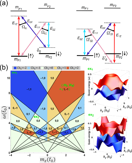
The scheme.—Our proposed scheme for realizing 2D SO couplings beyond RWA builds on a spin- Fermi gas in a 2D square optical Raman lattice Liu et al. (2014); Wang et al. (2018), with a temporal modulation naturally emerging from two sets of Raman couplings, which is depicted by a time-dependent Hamiltonian for two spin states and :
| (1) |
Here is the time, is the reduced Planck’s constant (set to 1 below), is the atomic momentum, is the atomic mass, denotes two-photon detuning, and are Pauli matrices. As illustrated in Fig. 1(a), the Raman coupling beyond RWA
| (4) |
contains two sets of Raman potentials and : and , with each set including two Raman couplings to drive SO couplings in and directions. Here relates to lattice spacing , equals to twice the frequency difference between two Raman coupling beams (say and ), is a tunable relative phase, and () denote the amplitudes of Raman couplings. The two-photon detuning for Raman couplings in is given by . The lattice potential is , with , where is the identity matrix, and () denote the optical lattice depths along the () direction for the two spin states. An effective Zeeman splitting is further defined as , where is the onsite energy of the () Wannier function at . Note that in the large- limit, the term in Eq. (4) can be neglected, known as the RWA, and Eq. (1) realizes the Qi-Wu-Zhang model Qi et al. (2006); Liu et al. (2014); Liang et al. (2023).
Equations (1) and (4) describe the new scheme with modulated SO couplings. The main results can be captured by considering tight-binding regime with only the nearest-neighbor hopping terms. We obtain for the temporally modulated Bloch Hamiltonian as
| (5) |
where is the Bloch wavevector and is an overall energy shift. Here, the transverse couplings and are temporally modulated and defined by , leading to , , with and acting as the modulation angular frequency. The time-independent is given by , where and represent the spin-flip and mean value of spin-conserved () hopping coefficients, respectively.
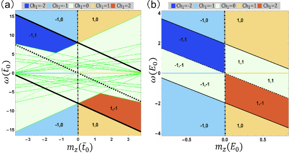
The above Bloch Hamiltonian (5) characterizes a novel and robust Floquet topological system resulted from SO couplings beyond RWA, which is different from the counterparts realized using photonic Kitagawa et al. (2012); Hu et al. (2015); Maczewsky et al. (2017); Mukherjee et al. (2017); D’Errico et al. (2020) and phononic Peng et al. (2016) systems and ultracold bosons Wintersperger et al. (2020); Zhang et al. (2023). The modulation of near-resonant Raman couplings can drive new types of effective SO couplings from the Floquet high-order effects, which may further contribute to novel topological physics. Fig. 1(b) shows a diagram with rich anomalous topological phases characterized by two winding numbers , which count the numbers of chiral edge modes inside the associated quasi-energy gaps and determine the Chern number by Kitagawa et al. (2010); Rudner et al. (2013); Nathan and Rudner (2015); Roy and Harper (2017); Nathan et al. (2019); Rudner and Lindner (2020); Eckardt (2017); Zhang et al. (2020); Zhang and Liu (2022). Using quasi-energy band analysis Floquet (1883); Shirley (1965); Eckardt (2017); Zhang et al. (2020); Zhang and Liu (2022), we determine the topological phase boundaries by identifying two types of band-inversion surfaces (BISs), the -BIS and -BIS, which are rings in 2D systems and depict where band crossing occurs, and originate from both the static () and modulated () Raman couplings Zhang et al. (2020); Zhang and Liu (2022). The winding number () can be reduced to contributions of all the -BISs (-BISs) Zhang et al. (2020); Zhang and Liu (2022). Thus, via regulating and , the system will enter a new topological phase whenever one BIS emerges or disappears. Note that under time-reversal transformation, both and reverse sign, and topological invariants change sign accordingly. Thus the part is not shown here but can be easily obtained.
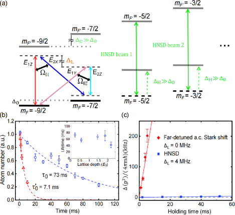
Experimental setup.—We realize the beyond-RWA scheme in a Fermi gas of 87Sr atoms with and ; see Fig. 2(a) and the Supplemental Material SM (2) for the setup. Compared to previous setups Liu et al. (2014); Wu et al. (2016); Sun et al. (2018a); Song et al. (2019); Wang et al. (2021); Liang et al. (2023), the two-level energy splitting of the present system is reduced to near zero, such that even moderate SO coupling strength is comparable to the energy splitting, bringing the system into the beyond-RWA regime in a unique manner that is advantageous for reaching a long lifetime.
We make two improvements for the experimental realization. First, we develop a highly nonlinear spin-discriminating (HNSD) method, by which and are very well isolated from nearby states. As shown in Fig. 2(a), adjacent 3P1 spin excited states (with ) are energetically separated by MHz under a 35-G magnetic field, whereas spin ground states are barely separated (). Two -polarized HNSD lasers are applied with frequencies that are near resonance of the -conserving -transitions for the unwanted states (with and ) but detuned from -transitions for and . Unlike the far-detuned a.c. Stark shift method where and experience large shifts Song et al. (2016, 2019); Liang et al. (2023), the HNSD method poses minimal perturbation to and (with only kHz-scale shifts), but strongly up-shifts the unwanted states by of more than 100 kHz SM (2) [see Fig. 2(a)]. Thus, the HNSD method realizes a well isolated effective spin- manifold of energetically nearly degenerate and states in a beyond-RWA regime. Second, to minimize detrimental interference effects Liang et al. (2023), we implement a large frequency difference between similarly polarized beam components ( or ) SM (2), such that optical lattices remain essentially static and atomic heating due to moving lattice potentials Liang et al. (2023) is vastly suppressed.
Long-lived 2D-SO-coupled fermions.—Under the new setup, we enhance the lifetime of 2D-SO-coupled fermions by an order of magnitude. Figure 2(b) shows a long lifetime that reaches 73 ms, as compared with ms based on the conventional far-detuned a.c. Stark shift method Song et al. (2016); Liang et al. (2023) under similar lattice conditions. With a reference measurement under far-off-resonance SO couplings, we further extract a SO-coupling-restrained characteristic decay time 101 ms, showing the potential of our system for future improvements SM (2). Figure 2(b) inset shows that the lifetime remains fairly long under various average lattice depths up to about (limited by available optical power), where is the recoil energy. Furthermore, we measure the variance of atomic momentum distribution by time-of-flight (TOF) imaging after the fermions are held in the optical Raman lattice for various amount of time [Fig. 2(c)], revealing a significant reduction of heating by a factor of 500. These results demonstrate a long-lived platform of 2D-SO-coupled fermions.
Verification of SO couplings beyond RWA.—A key feature of our beyond-RWA scheme is the simultaneous generation of two sets of SO couplings naturally related to each other. From Eq. (4), the sum of two relative phases for SO couplings driven by Raman potentials and equals an intrinsically fixed value of SM (2). Thus, when one SO coupling is tuned to be quasi-1D in the direction, the other will be quasi-1D in the orthogonal direction, providing a characteristic signature of SO couplings beyond RWA.
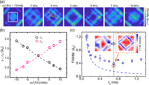
For verification, we probe fermions with quasi-1D SO couplings using the recently developed pump-probe quench measurement (PPQM) method Liang et al. (2023). Atoms initially prepared in the state experience SO-coupling-induced, quasi-momentum-dependent spin flip into under a short pulse of optical Raman lattice, and are subsequently probed by spin-resolved TOF measurements. Fig. 3(a) shows TOF images measured for various . As increases, we observe two groups of atoms: one group (black dashed lines) moves toward the center of the first Brillouin zone (FBZ) along the direction; the other (magenta dashed lines) moves away from the center along . The two-photon detunings and [see Fig. 1(a)] indicate that the effective Zeeman splittings for the two sets of SO couplings depend on in reverse ways. We identify the two groups as pumped respectively by the two quasi-1D SO couplings in the orthogonal directions of , corresponding to relative phases of and 0 for the two SO couplings (with a sum of ). The measured highly symmetric movements (with respect to ) of the two atomic groups with opposite effective Zeeman splittings show unambiguously the realization of SO couplings beyond RWA, as further supported by agreement between measurements and numerical results by exact diagonalization in the non-tight-binding regime Liang et al. (2023); SM (2) (Fig. 3(b)).
The PPQM resolution can be sharpened by optimizing the pulse length under a fixed pulse area SM (2). Figure 3(c) shows a minimum atomic ring width at s that is used in subsequent measurements.

Experimental exploration of Floquet topological phase diagram.—We explore the Floquet topological phase diagram by a systematic measurement of BIS configurations. The noninteracting topological phases can be generically characterized by the dimension-reduced topological invariants on BISs Zhang et al. (2018); Zhu et al. (2020); Zhang et al. (2020); Ye and Li (2020); Li et al. (2021); Zhang and Liu (2022); Zhang et al. (2022), which provides feasible schemes to detect bulk topology Sun et al. (2018b); Hu and Zhao (2020); Yu et al. (2021); Song et al. (2019); Yi et al. (2019); Wang et al. (2019); Ji et al. (2020); Xin et al. (2020); Liang et al. (2023); Zhang et al. (2023). For Chern bands in 2D optical Raman lattices, measuring the BIS configuration alone can yield precise information of the bulk topology Sun et al. (2018b); Liang et al. (2023); Zhang et al. (2023). In this setup, Raman couplings and optical lattices are relatively weak, such that the relevant topology is dominated by leading-order SO couplings, while the effect of higher-order couplings can be ignored SM (2). Below we shall show that leading-order SO couplings alone lead to nontrivial topology.
We tune the SO coupling beyond RWA to the optimum 2D configuration by setting , and then perform a systematic PPQM study by varying . In Fig. 4(a), we observe two BISs that emerge from M () and points in the FBZ, evolving toward each other, switching positions at , and finally shrink at and M, respectively not . This observation agrees with numerical simulation in Fig. 4(b) SM (2). In Fig. 4(c), we quantify the observation by measuring sizes of the two BISs versus , which also shows agreement with numerical results. The systematic measurements of BIS configurations, which match well with the numerical study, unveil the underlying nontrivial topological regimes realized in the experiment, as we elaborate below.
In Fig. 4(d), we compute a simplified phase diagram with experimental parameters by considering only leading-order SO couplings 111The sub-leading-order SO coupling, which is a third-order coupling, has a strength estimated to be on the scale of Hz, which is not relevant in the current measurements; see more details in the Supplemental Material SM (2)., and compare it with the systematic measurements in Fig. 4(a), which scan through the high-Chern-number regime with SM (2). This regime is characterized by that the two BISs observed in Fig. 4(a) correspond to a 0-BIS (black) and a -BIS (magenta), and are induced by two sets of SO couplings, respectively SM (2). Such two BISs correspond to opposite effective Zeeman splittings and carry opposite winding numbers according to previous studies Zhang et al. (2020); Zhang and Liu (2022), yielding and a high Chern number . At , the measurement reduces to a single-ring BIS with for a static Hamiltonian. These results indirectly show that the present experiment has achieved a fermionic anomalous Floquet topological system. A direct observation of topological invariants can be achieved by measuring winding numbers on BISs Zhang et al. (2020); Zhang and Liu (2022); Yi et al. (2019) and will be presented in next studies.
Conclusion and discussion.—In summary, we have realized 2D SO coupling beyond RWA for ultracold fermions with a long lifetime and observed various BIS configurations that provide an indirect measurement of the nontrivial topology engineered in the current system. The SO coupling beyond RWA renders an intrinsic temporal engineering, giving rise to a rich Floquet topological phase diagram with high-Chern-number states. Together with the HNSD method developed in our experiment, the 2D-SO-coupled Floquet fermion system has a long lifetime, which can be further improved SM (2) and fulfills a key prerequisite for future studies of novel correlated topological phases including the topological superfluid, dynamical gauge fields, and quantum magnetism in the interacting regimes Liu et al. (2014); Ziegler et al. (2022a, b); Radic et al. (2012); Reuther et al. (2012). The present scheme can be naturally generalized to engineer an isolated manifold of an arbitrary number of spin states for SO-coupled Fermi gases Barnett et al. (2012); Lauria et al. (2022). Applying the beyond-RWA scheme to such large-spin systems can lead to fundamentally new type of SO couplings and can potentially bring about profound spin-orbit and topological physics, which deserves efforts in future studies.
Acknowledgments.—We are grateful to Murray Barrett for very insightful discussions. We thank Shize Du, Tao Deng, Wei Qi, Yu-Dong Wei for discussions and technical support. This work is supported by the Chinese Academy of Sciences Strategic Priority Research Program under Grant No. XDB35020100, the National Key Research and Development Program of China under Grant Nos 2018YFA0305601 and 2021YFA1400900, the National Natural Science Foundation of China (No. 11874073, 11825401, 12204187, 12261160368), the Open Project of Shenzhen Institute of Quantum Science and Engineering (Grant No. SIQSE202003), the Hefei National Laboratory, and the Scientific and Technological Innovation 2030 Key Program of Quantum Communication and Quantum Computing under Grant Nos. 2021ZD0301903 and 2021ZD0302000. X.Z. and X.-J.L. conceived the project. H.Z., W.-W.W., C.Q. performed the experiments. C.Q., L.Z., H.Z., W.-W.W. performed the numerical computations. All authors contribute to the data analysis and the writing of this manuscript.
References
- Koralek et al. (2009) J. D. Koralek, C. P. Weber, J. Orenstein, B. A. Bernevig, S.-C. Zhang, S. Mack, and D. D. Awschalom, Nature 458, 610 (2009).
- Bernevig et al. (2006) B. A. Bernevig, T. L. Hughes, and S.-C. Zhang, Science 314, 1757 (2006).
- Konig et al. (2007) M. Konig, S. Wiedmann, C. Brune, A. Roth, H. Buhmann, L. W. Molenkamp, X.-L. Qi, and S.-C. Zhang, Science 318, 766 (2007).
- Qi et al. (2006) X.-L. Qi, Y.-S. Wu, and S.-C. Zhang, Physical Review B 74, 085308 (2006).
- Yu et al. (2010) R. Yu, W. Zhang, H.-J. Zhang, S.-C. Zhang, X. Dai, and Z. Fang, Science 329, 61 (2010).
- Chang et al. (2013) C.-Z. Chang, J. Zhang, X. Feng, J. Shen, Z. Zhang, M. Guo, K. Li, Y. Ou, P. Wei, L.-L. Wang, Z.-Q. Ji, Y. Feng, S. Ji, X. Chen, J. Jia, X. Dai, Z. Fang, S.-C. Zhang, K. He, Y. Wang, L. Lu, X.-C. Ma, and Q.-K. Xue, Science 340, 167 (2013).
- Checkelsky et al. (2014) J. G. Checkelsky, R. Yoshimi, A. Tsukazaki, K. S. Takahashi, Y. Kozuka, J. Falson, M. Kawasaki, and Y. Tokura, Nature Physics 10, 731 (2014).
- Kou et al. (2014) X. Kou, S.-T. Guo, Y. Fan, L. Pan, M. Lang, Y. Jiang, Q. Shao, T. Nie, K. Murata, J. Tang, Y. Wang, L. He, T.-K. Lee, W.-L. Lee, and K. L. Wang, Physical Review Letters 113, 137201 (2014).
- He et al. (2014) K. He, Y. Wang, and Q.-K. Xue, National Science Review 1, 38 (2014).
- Hasan and Kane (2010) M. Z. Hasan and C. L. Kane, Reviews of Modern Physics 82, 3045 (2010).
- Qi and Zhang (2011) X.-L. Qi and S.-C. Zhang, Reviews of Modern Physics 83, 1057 (2011).
- Asbóth et al. (2016) J. K. Asbóth, L. Oroszlány, and A. Pályi, A Short Course on Topological Insulators (Springer, 2016).
- Yan and Felser (2017) B. Yan and C. Felser, Annu. Rev. Condens. Matter Phys. 8, 337 (2017).
- Armitage et al. (2018) N. P. Armitage, E. J. Mele, and A. Vishwanath, Reviews of Modern Physics 90, 015001 (2018).
- Lv et al. (2021) B. Q. Lv, T. Qian, and H. Ding, Reviews of Modern Physics 93, 025002 (2021).
- Sato and Ando (2017) M. Sato and Y. Ando, Reports on Progress in Physics 80, 076501 (2017).
- Sharma et al. (2022) M. M. Sharma, P. Sharma, N. K. Karn, and V. P. S. Awana, Superconductor Science and Technology 35, 083003 (2022).
- Dalibard et al. (2011) J. Dalibard, F. Gerbier, G. Juzeliunas, and P. Ohberg, Reviews of Modern Physics 83, 1523 (2011).
- Goldman et al. (2014) N. Goldman, G. Juzeliunas, P. Ohberg, and I. B. Spielman, Reports on Progress in Physics 77, 126401 (2014).
- Zhai (2015) H. Zhai, Reports on Progress in Physics 78, 026001 (2015).
- Zhang and Liu (2018) L. Zhang and X.-J. Liu, in Synthetic Spin-Orbit Coupling in Cold Atoms, edited by W. Zhang, W. Yi, and C. A. R. S. de Melo (World Scientific, Singapore, 2018) Chapter 1, pp. 1–87.
- Lin et al. (2011) Y.-J. Lin, K. Jimenez-Garcia, and I. B. Spielman, Nature 471, 83 (2011).
- Zhang et al. (2012) J.-Y. Zhang, S.-C. Ji, Z. Chen, L. Zhang, Z.-D. Du, B. Yan, G.-S. Pan, B. Zhao, Y.-J. Deng, H. Zhai, S. Chen, and J.-W. Pan, Physical Review Letters 109, 115301 (2012).
- Beeler et al. (2013) M. C. Beeler, R. A. Williams, K. Jimenez-Garcia, L. J. LeBlanc, A. R. Perry, and I. B. Spielman, Nature 498, 201 (2013).
- Ji et al. (2014) S.-C. Ji, J.-Y. Zhang, L. Zhang, Z.-D. Du, W. Zhang, Y.-J. Deng, H. Zhai, S. Chen, and J.-W. Pan, Nature Physics 10, 314 (2014).
- Hamner et al. (2014) C. Hamner, C. Qu, Y. Zhang, J. Chang, M. Gong, C. Zhang, and P. Engels, Nature Communications 5, 4023 (2014).
- Olson et al. (2014) A. J. Olson, S.-J. Wang, R. J. Niffenegger, C.-H. Li, C. H. Greene, and Y. P. Chen, Physical Review A 90, 013616 (2014).
- Atala et al. (2014) M. Atala, M. Aidelsburger, M. Lohse, J. T. Barreiro, B. Paredes, and I. Bloch, Nature Physics 10, 588 (2014).
- Li et al. (2016) J. Li, W. Huang, B. Shteynas, S. Burchesky, F. C. Top, E. Su, J. Lee, A. O. Jamison, and W. Ketterle, Physical Review Letters 117, 185301 (2016).
- Li et al. (2017) J.-R. Li, J. Lee, W. Huang, S. Burchesky, B. Shteynas, F. C. Top, A. O. Jamison, and W. Ketterle, Nature 543, 91 (2017).
- Valdes-Curiel et al. (2017) A. Valdes-Curiel, D. Trypogeorgos, E. E. Marshall, and I. B. Spielman, New Journal of Physics 19, 033025 (2017).
- Chen et al. (2018) H.-R. Chen, K.-Y. Lin, P.-K. Chen, N.-C. Chiu, J.-B. Wang, C.-A. Chen, P. Huang, S.-K. Yip, Y. Kawaguchi, and Y.-J. Lin, Physical Review Letters 121, 113204 (2018).
- Zhang et al. (2019) D. Zhang, T. Gao, P. Zou, L. Kong, R. Li, X. Shen, X.-L. Chen, S.-G. Peng, M. Zhan, H. Pu, and K. Jiang, Physical Review Letters 122, 110402 (2019).
- Wang et al. (2012) P. Wang, Z.-Q. Yu, Z. Fu, J. Miao, L. Huang, S. Chai, H. Zhai, and J. Zhang, Physical Review Letters 109, 095301 (2012).
- Cheuk et al. (2012) L. W. Cheuk, A. T. Sommer, Z. Hadzibabic, T. Yefsah, W. S. Bakr, and M. W. Zwierlein, Physical Review Letters 109, 095302 (2012).
- Williams et al. (2013) R. A. Williams, M. C. Beeler, L. J. LeBlanc, K. Jimenez-Garcia, and I. B. Spielman, Physical Review Letters 111, 095301 (2013).
- Zhang et al. (2014) J. Zhang, H. Hu, X.-J. Liu, and H. Pu, Annual Review of Cold Atoms and Molecules 2, 81 (2014).
- Burdick et al. (2016) N. Q. Burdick, Y. Tang, and B. L. Lev, Physical Review X 6, 031022 (2016).
- Livi et al. (2016) L. F. Livi, G. Cappellini, M. Diem, L. Franchi, C. Clivati, M. Frittelli, F. Levi, D. Calonico, J. Catani, M. Inguscio, and L. Fallani, Physical Review Letters 117, 220401 (2016).
- Song et al. (2016) B. Song, C. He, S. Zhang, E. Hajiyev, W. Huang, X.-J. Liu, and G.-B. Jo, Physical Review A 94, 061604(R) (2016).
- Kolkowitz et al. (2017) S. Kolkowitz, S. L. Bromley, T. Bothwell, M. L. Wall, G. E. Marti, A. P. Koller, X. Zhang, A. M. Rey, and J. Ye, Nature 542, 66 (2017).
- Jaksch and Zoller (2003) D. Jaksch and P. Zoller, New Journal of Physics 5, 56 (2003).
- Juzeliunas and Ohberg (2004) G. Juzeliunas and P. Ohberg, Physical Review Letters 93, 033602 (2004).
- Liu et al. (2006) X.-J. Liu, H. Jing, X. Liu, and M.-L. Ge, The European Physical Journal D 37, 261 (2006).
- Zhu et al. (2006) S.-L. Zhu, H. Fu, C.-J. Wu, S.-C. Zhang, and L.-M. Duan, Physical Review Letters 97, 240401 (2006).
- Liu et al. (2007) X.-J. Liu, X. Liu, L. C. Kwek, and C. H. Oh, Physical Review Letters 98, 026602 (2007).
- Liu et al. (2009) X.-J. Liu, M. F. Borunda, X. Liu, and J. Sinova, Physical Review Letters 102, 046402 (2009).
- Spielman (2009) I. B. Spielman, Physical Review A 79, 063613 (2009).
- Lin et al. (2009) Y.-J. Lin, R. L. Compton, K. Jimenez-Garcia, J. V. Porto, and I. B. Spielman, Nature 462, 628 (2009).
- Campbell et al. (2011) D. L. Campbell, G. Juzeliunas, and I. B. Spielman, Physical Review A 84, 025602 (2011).
- Galitski and Spielman (2013) V. Galitski and I. B. Spielman, Nature 494, 49 (2013).
- Liu et al. (2014) X.-J. Liu, K. T. Law, and T. K. Ng, Physical Review Letters 112, 086401 (2014).
- Mancini et al. (2015) M. Mancini, G. Pagano, G. Cappellini, L. Livi, M. Rider, J. Catani, C. Sias, P. Zoller, M. Inguscio, M. Dalmonte, and L. Fallani, Science 349, 1510 (2015).
- Stuhl et al. (2015) B. K. Stuhl, H.-I. Lu, L. M. Aycock, D. Genkina, and I. B. Spielman, Science 349, 1514 (2015).
- An et al. (2017) F. A. An, E. J. Meier, and B. Gadway, Science Advances 3, e1602685 (2017).
- Wang et al. (2018) B.-Z. Wang, Y.-H. Lu, W. Sun, S. Chen, Y. Deng, and X.-J. Liu, Phys. Rev. A 97, 011605(R) (2018).
- Peng et al. (2022) S.-G. Peng, K. Jiang, X.-L. Chen, K.-J. Chen, P. Zou, and L. He, AAPPS Bulletin 32, 36 (2022).
- Huang et al. (2016) L. Huang, Z. Meng, P. Wang, P. Peng, S.-L. Zhang, L. Chen, D. Li, Q. Zhou, and J. Zhang, Nature Physics 12, 540 (2016).
- Wu et al. (2016) Z. Wu, L. Zhang, W. Sun, X.-T. Xu, B.-Z. Wang, S.-C. Ji, Y. Deng, S. Chen, X.-J. Liu, and J.-W. Pan, Science 354, 83 (2016).
- Meng et al. (2016) Z. Meng, L. Huang, P. Peng, D. Li, L. Chen, Y. Xu, C. Zhang, P. Wang, and J. Zhang, Physical Review Letters 117, 235304 (2016).
- Song et al. (2019) B. Song, C. He, S. Niu, L. Zhang, Z. Ren, X.-J. Liu, and G.-B. Jo, Nature Physics 15, 911 (2019).
- Wang et al. (2021) Z.-Y. Wang, X.-C. Cheng, B.-Z. Wang, J.-Y. Zhang, Y.-H. Lu, C.-R. Yi, S. Niu, Y. Deng, X.-J. Liu, S. Chen, and J.-W. Pan, Science 372, 271 (2021).
- Li and Liu (2021) X. Li and W. V. Liu, Science Bulletin 66, 1253 (2021).
- Valdes-Curiel et al. (2021) A. Valdes-Curiel, D. Trypogeorgos, Q.-Y. Liang, R. P. Anderson, and I. B. Spielman, Nature Communications 12, 593 (2021).
- Lauria et al. (2022) P. Lauria, W.-T. Kuo, N. R. Cooper, and J. T. Barreiro, Physical Review Letters 128, 245301 (2022).
- Liang et al. (2023) M.-C. Liang, Y.-D. Wei, L. Zhang, X.-J. Wang, H. Zhang, W.-W. Wang, W. Qi, X.-J. Liu, and X. Zhang, Physical Review Research 5, L012006 (2023).
- Jaynes and Cummings (1963) E. T. Jaynes and F. W. Cummings, Proceedings of the IEEE 51, 89 (1963).
- Shore and Knight (1993) B. W. Shore and P. L. Knight, Journal of Modern Optics 40, 1195 (1993).
- Allen and Eberly (1975) L. Allen and J. H. Eberly, Optical resonance and two-level atoms (John Wiley & Sons, Inc., New York, 1975).
- Foot (2005) C. J. Foot, Atomic Physics (Oxford University Press, Great Clarendon Street, Oxford OX2 6DP, 2005).
- Zhai (2021) H. Zhai, Ultracold Atomic Physics (Cambridge University Press, University Printing House, Cambridge CB2 8BS, United Kingdom, 2021).
- Fuchs et al. (2009) G. D. Fuchs, V. V. Dobrovitski, D. M. Toyli, F. J. Heremans, and D. D. Awschalom, Science 326, 1520 (2009).
- Bloch and Siegert (1940) F. Bloch and A. Siegert, Physical Review 57, 522 (1940).
- Milonni et al. (1983) P. W. Milonni, J. R. Ackerhalt, and H. W. Galbraith, Physical Review Letters 50, 966 (1983).
- Ng and Burnett (2008) H. T. Ng and K. Burnett, New Journal of Physics 10, 123014 (2008).
- Kitagawa et al. (2012) T. Kitagawa, M. A. Broome, A. Fedrizzi, M. S. Rudner, E. Berg, I. Kassal, A. Aspuru-Guzik, E. Demler, and A. G. White, Nature Communications 3, 882 (2012).
- Hu et al. (2015) W. Hu, J. C. Pillay, K. Wu, M. Pasek, P. P. Shum, and Y. D. Chong, Physical Review X 5, 011012 (2015).
- Maczewsky et al. (2017) L. J. Maczewsky, J. M. Zeuner, S. Nolte, and A. Szameit, Nature Communications 8, 13756 (2017).
- Mukherjee et al. (2017) S. Mukherjee, A. Spracklen, M. Valiente, E. Andersson, P. Ohberg, N. Goldman, and R. R. Thomson, Nature Communications 8, 13918 (2017).
- D’Errico et al. (2020) A. D’Errico, F. Cardano, M. Maffei, A. Dauphin, R. Barboza, C. Esposito, B. Piccirillo, M. Lewenstein, P. Massignan, and L. Marrucci, Optica 7, 108 (2020).
- Peng et al. (2016) Y.-G. Peng, C.-Z. Qin, D.-G. Zhao, Y.-X. Shen, X.-Y. Xu, M. Bao, H. Jia, and X.-F. Zhu, Nature Communications 7, 13368 (2016).
- Wintersperger et al. (2020) K. Wintersperger, C. Braun, F. N. Unal, A. Eckardt, M. D. Liberto, N. Goldman, I. Bloch, and M. Aidelsburger, Nature Physics 16, 1058 (2020).
- Zhang et al. (2023) J.-Y. Zhang, C. R. Yi, L. Zhang, R.-H. Jiao, K.-Y. Shi, H. Yuan, W. Zhang, X.-J. Liu, S. Chen, and J.-W. Pan, Physical Review Letters 130, 043201 (2023).
- Kitagawa et al. (2010) T. Kitagawa, E. Berg, M. Rudner, and E. Demler, Physical Review B 82, 235114 (2010).
- Rudner et al. (2013) M. S. Rudner, N. H. Lindner, E. Berg, and M. Levin, Physical Review X 3, 031005 (2013).
- Nathan and Rudner (2015) F. Nathan and M. S. Rudner, New Journal of Physics 17, 125014 (2015).
- Roy and Harper (2017) R. Roy and F. Harper, Physical Review B 96, 155118 (2017).
- Nathan et al. (2019) F. Nathan, D. Abanin, E. Berg, N. H. Lindner, and M. S. Rudner, Physical Review B 99, 195133 (2019).
- Rudner and Lindner (2020) M. S. Rudner and N. H. Lindner, Nature Reviews Physics 2, 229 (2020).
- Eckardt (2017) A. Eckardt, Reviews of Modern Physics 89, 011004 (2017).
- Zhang et al. (2020) L. Zhang, L. Zhang, and X.-J. Liu, Physical Review Letters 125, 183001 (2020).
- Zhang and Liu (2022) L. Zhang and X.-J. Liu, PRX Quantum 3, 040312 (2022).
- Floquet (1883) M. G. Floquet, Annales Scientifiques de l’Ecole Normale Superieure 12, 47 (1883).
- Shirley (1965) J. H. Shirley, Phys. Rev. 138, B979 (1965).
- SM (2) Supporting information is available as Supplemental Material .
- Sun et al. (2018a) W. Sun, B.-Z. Wang, X.-T. Xu, C.-R. Yi, L. Zhang, Z. Wu, Y. Deng, X.-J. Liu, S. Chen, and J.-W. Pan, Physical Review Letters 121, 150401 (2018a).
- Zhang et al. (2018) L. Zhang, L. Zhang, S. Niu, and X.-J. Liu, Science Bulletin 63, 1385 (2018).
- Zhu et al. (2020) B. Zhu, Y. Ke, H. Zhong, and C. Lee, Physical Review Research 2, 023043 (2020).
- Ye and Li (2020) J. Ye and F. Li, Physical Review A 102, 042209 (2020).
- Li et al. (2021) L. Li, W. Zhu, and J. Gong, Science Bulletin 66, 1502 (2021).
- Zhang et al. (2022) L. Zhang, W. Jia, and X.-J. Liu, Science Bulletin 67, 1236 (2022).
- Sun et al. (2018b) W. Sun, C.-R. Yi, B.-Z. Wang, W.-W. Zhang, B. C. Sanders, X.-T. Xu, Z.-Y. Wang, J. Schmiedmayer, Y. Deng, X.-J. Liu, S. Chen, and J.-W. Pan, Physical Review Letters 121, 250403 (2018b).
- Hu and Zhao (2020) H. Hu and E. Zhao, Physical Review Letters 124, 160402 (2020).
- Yu et al. (2021) X.-L. Yu, W. Ji, L. Zhang, Y. Wang, J. Wu, and X.-J. Liu, PRX Quantum 2, 020320 (2021).
- Yi et al. (2019) C.-R. Yi, L. Zhang, L. Zhang, R.-H. Jiao, X.-C. Cheng, Z.-Y. Wang, X.-T. Xu, W. Sun, X.-J. Liu, S. Chen, and J.-W. Pan, Physical Review Letters 123, 190603 (2019).
- Wang et al. (2019) Y. Wang, W. Ji, Z. Chai, Y. Guo, M. Wang, X. Ye, P. Yu, L. Zhang, X. Qin, P. Wang, F. Shi, X. Rong, D. Lu, X.-J. Liu, and J. Du, Physical Review A 100, 052328 (2019).
- Ji et al. (2020) W. Ji, L. Zhang, M. Wang, L. Zhang, Y. Guo, Z. Chai, X. Rong, F. Shi, X.-J. Liu, Y. Wang, and J. Du, Physical Review Letters 125, 020504 (2020).
- Xin et al. (2020) T. Xin, Y. Li, Y. ang Fan, X. Zhu, Y. Zhang, X. Nie, J. Li, Q. Liu, and D. Lu, Physical Review Letters 125, 090502 (2020).
- (109) We note that in Fig. 4(a), the observed weak connections between two BISs are contributed from the atoms initially populated outside the first Brillouin zone SM (2) .
- Note (1) The sub-leading-order SO coupling, which is a third-order coupling, has a strength estimated to be on the scale of Hz, which is not relevant in the current measurements; see more details in the Supplemental Material SM (2).
- Ziegler et al. (2022a) L. Ziegler, E. Tirrito, M. Lewenstein, S. Hands, and A. Bermudez, Physical Review Research 4, L042012 (2022a).
- Ziegler et al. (2022b) L. Ziegler, E. Tirrito, M. Lewenstein, S. Hands, and A. Bermudez, Annals of Physics 439, 168763 (2022b).
- Radic et al. (2012) J. Radic, A. D. Ciolo, K. Sun, and V. Galitski, Physical Review Letters 109, 085303 (2012).
- Reuther et al. (2012) J. Reuther, R. Thomale, and S. Rachel, Physical Review B 86, 155127 (2012).
- Barnett et al. (2012) R. Barnett, G. R. Boyd, and V. Galitski, Physical Review Letters 109, 235308 (2012).
- Jimenez-Garcia et al. (2015) K. Jimenez-Garcia, L. J. LeBlanc, R. A. Williams, M. C. Beeler, C. Qu, M. Gong, C. Zhang, and I. B. Spielman, Physical Review Letters 114, 125301 (2015).
SUPPLEMENTAL MATERIAL
I Experimental setup and methods
I.1 Preparation and detection of Fermi gases
The preparation of strontium (87Sr) ultracold Fermi gases and the detection of two spin states are performed in a way similar to Ref. 66. The two relevant spin ground states are and . Fermions of 87Sr are first laser-cooled and then evaporatively cooled to a temperature below 200 nK. The corresponding ultracold Fermi gas has about atoms in a far-detuned crossed dipole trap, with more than of these atoms initially populated in the state.
After the Fermi gas is loaded into the optical Raman lattice and the experiment is performed, we shut off all lasers within 1 s and perform spin-resolved time-of-flight measurements to extract the distribution of the and atoms Liang et al. (2023).
I.2 Two-dimensional optical Raman lattice
The experimental setup for the two-dimensional optical Raman lattice is illustrated in Fig. S1(a). Two Raman coupling beams propagate along the and horizontal directions, intersect at the atoms, and are each phase-shifted and retro-reflected to form two-dimensional (2D) optical lattices for the and states. Here, , , and denote a set of orthogonal spatial axes, with being the direction of the gravity.
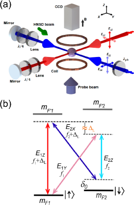
The Raman coupling beams of wavelength nm are set to a frequency of about -0.8 GHz with respect to the 1SP1() intercombination transition for the 87Sr atoms, where the transition linewidth is as narrow as 7.5 kHz. A total of four two-photon Raman transitions between the and states can be induced by pairs of electric field components: , , , and . Here, in the combination , corresponds to the absorption of one photon from the beam, and corresponds to the emission of one photon into the beam. As shown in Fig. 1(a) of the main text, the first two combinations, and , correspond to Raman couplings with a two-photon detuning . By contrast, the rest two combinations, and , correspond to Raman couplings with a distinct two-photon detuning , where equals to twice the frequency difference between two Raman coupling beams (say and ); see the main text below Eq. 2.
Realization of essentially static 2D optical lattice.— It has been observed that the interference between similarly polarized electric field components (such as and ) can cause detrimental moving lattice potentials that heat up the atoms Liang et al. (2023). Such detrimental effect can be suppressed by implementing a large frequency difference between two pairs of electric fields, namely the vertically polarized pair and the horizontally polarized pair .
As shown in Fig. S1(b), we introduce large frequency differences (close to MHz) between these pairs of similarly polarized electric fields; see also Fig. 2(a) and Fig. 1(a) in the main text. Here, is on the megahertz scale and is three orders of magnitude larger than two physical quantities: (a) the kilohertz-scale level splitting between the and states and (b) typical two-photon detuning values that are also on the kilohertz scale. In the experimental implementation, for each Raman coupling beam, the vertical and horizontal linear polarization components are two single-frequency laser beams of distinct frequencies, with a large frequency difference between the two. We note that the large and the two-photon detuning () for Raman couplings are fully independent parameters that are precisely controlled in the experiment. The detailed structure of this optical implementation is not required for the understanding of this work, and will be presented elsewhere in a more specialized journal.
The choice of is based on two considerations. First, in our experiment, we have verified that as long as reaches a few MHz, the heating effect due to moving lattice potentials can be sufficiently suppressed. Second, can not be too large, either. This is because, under the same physical distance between atoms and the retro-reflection mirror, the frequency difference between two polarization components will cause a mismatch between the lattice potential minima for these two polarization components. Under MHz and a distance of m between atoms and the retro-reflection mirror, the mismatch is about , where nm is the lattice spacing for both polarization components. This mismatch is sufficiently small and thus neglected in our analysis.
I.3 The highly nonlinear spin-discriminating method
We design and implement a highly nonlinear spin-discriminating (HNSD) method to isolate an effective two-spin manifold out of the ten nuclear spin ground states of 87Sr. In our case of two-photon Raman transitions, we need to well separate the two nearby spin ground states ( and ) from the two-spin manifold of the and states. To achieve this goal, we first magnetically separate the energy levels of 3P1 excited states, and then apply HNSD beams that are (1) near-resonance for the -transitions of the or state and (2) relatively farther-detuned from transitions of the and states.
In our experiment, a relatively large magnetic field of 35 G is applied along the direction, which both determines the quantization axis for the atomic states and induces a large level splitting of MHz between adjacent spin excited states in the excited manifold. By contrast, adjacent spin ground states are separated by a much smaller amount of about 6 kHz under the same field. Under such magnetic Zeeman splittings, we apply to atoms a -polarized HNSD beam that propagate in the horizontal plane along a direction 20 degree with respect to . This HNSD beam, with 80 W power and a beam radius of 200 m, contains two frequency modes in its spectrum. Each frequency mode has a narrow linewidth below 1 kHz and is about 100 kHz blue-detuned relative to the resonance of the -transition 1SP at or . As a result, the HNSD beam induces large upward level shifts (more than 100 kHz) for the and spin ground states. By contrast, this beam only induces kilohertz-scale small level shift for the and states, which has a high stability on the 10-hertz scale based on laser intensity stabilization technique. Thus, compared to the Zeeman shift that is linear to the lowest order (and at small magnetic field), the HNSD method engineers highly nonlinear energy level shifts among the spin states, which both enhances the lifetime of SO-coupled fermions and holds promise for creating an isolated manifold with an arbitrary number of spin states.
I.4 Lifetime measurement and analysis
The lifetime of SO-coupled fermions is determined as follows. We hold the atoms in the optical Raman lattice for various length of time, measure the total number of atoms in the and states as a function of holding time, and fit the measure with a first-order exponential decay function, extracting a decay lifetime.
As described in the main text, we enhance the lifetime of 2D-SO-coupled fermions by an order of magnitude. Such enhancement builds on two technical improvements that are also described in the main text, namely the HNSD method and the upgraded method for generating the optical Raman lattice. These two improvements for the experimental realization are both indispensable to the lifetime enhancement. In fact, during our experimental period, we first implemented the optical Raman lattice upgrade, and observed the lifetime doubled, which was encouraging but still insufficient. Later we developed and implemented the HNSD method, and achieved another enhancement factor of about 5 for the lifetime. These two improvements together enable the one-order-of-magnitude lifetime enhancement.
In addition, we perform a similar measurement when the SO couplings are far-off-resonance, and extract a reference lifetime ms under the same lattice depths and Raman coupling strengths as those in Fig. 2(b) in the main text. Comparing ms and , we see that the near-resonant SO-couplings still play an important role in affecting the lifetime. We further extract a SO-coupling-constrained characteristic decay lifetime, , based on an empirical form: . This analysis yields ms, which is shorter than . Therefore, compared to other factors (revealed by ), the SO couplings currently do impose a primary constraint on the lifetime of SO-coupled fermions, which can be further improved in future experiments; see next paragraph. At the same time, such a SO-coupling constrained lifetime already reaches the 100 ms scale and can enable a number of precise measurements for various topological phases.
The lifetime of 2D-SO-coupled fermions in our system is currently limited by several factors that can be further improved in future experiments. First, from the fundamental aspect, when the SO coupling is close to the two-photon resonance, the fluctuation of the two-photon detuning can induce heating effects, which is similar to the magnetic-field-induced heating effect in the 2D-SO-coupled bosonic systems Wu et al. (2016). Thus, the lifetime can be further enhanced by improving the stability of the relative energy splitting between the and states. Second, we can further reduce the photon scattering in our setup. For example, applying a larger magnetic field can reduce the residual scattering rate due to the HNSD beams for the and states. The photon scattering due to the Raman beams can also be reduced by implementing a Ti:Sapphire laser that provides a cleaner spectrum, higher optical power and larger single-photon detunings for the optical Raman lattices. Third, the heating due to residual moving lattice potentials can be further suppressed by improving the laser polarization purity with better polarizing optics. The systematic technical improvements can further remove the major technical impediments to enhancing the lifetime and allow us to focus on improving the fundamental, SO-coupling-related factors for the Fermi gases. Overall, our system of 2D-SO-coupled Fermi gas holds the promise to reach an even longer lifetime that approaches the performance in Ref. 38 or even that in the bosonic systems Wu et al. (2016); Sun et al. (2018a).
We also note that, when the lattice depth is increased to even higher values, the aforementioned several improvements will similarly alleviate the issues of increased scattering rate and residual moving lattice potentials. This is beneficial for reaching a sufficiently long lifetime under the corresponding experimental condition and for future studies of novel correlated topological physics in the interacting regimes.
I.5 Optimization of PPQM pulse length
The long lifetime enables us to sharpen the detection resolution of the PPQM measurement. Under a given PPQM pulse area, the Fourier-limited width of atomic distribution for the observed -state atoms decreases as the pulse becomes longer. The key in this optimization is to search for a balance between the Fourier broadening and other factors.
In Fig. 3(c) of the main text, we employ a fixed pulse area of , the measured momentum-width of pumped -state atoms indeed decreases as the pulse length increases from a small value (about 100 s), which is consistent with a reduction of the Fourier limit of a finite pulse (); see the blue dashed line in Fig. 3(c). For exceeding 800 s, the atomic width stops improving, which is likely due to other factors such as the finite imaging resolution. An optimum value of s is found, providing substantial better resolving power than the 200 s used in Ref. 66.
II Key characteristic feature of SO couplings beyond RWA
The two Raman potentials, and , are generated from the same electric fields in two different but intrinsically related ways. Below we shall show that the sum of the two relative phases for SO couplings driven by Raman potentials and equals to a deterministic value of , which is dictated by the phase relation between dipole oscillations with respect to different spatial axes.
For the Raman potential , the relative phase between the two Raman processes [ and in Figs. 1(a) and 2(a) in the main text] is determined by
| (S1) |
where is the relative phase shift induced by the laser and optics in the setup Liang et al. (2023), and denotes the phase of the dipole matrix element for the transition from the ground state 1S to an excited state 3P, with , where the transition is driven by the dipole operator and an unit vector along the relevant electric field polarization, with in our experimental implementation. In Eq. (S1), the minus sign in marks the “emission” of a photon. Here for simplicity of expression, we only show the terms for transitions driven by horizontally polarized electric fields. The phase terms of the transitions driven by the vertically polarized electric fields are neglected because they do not influence the main conclusion in this section [Eq. (S3)].
Likewise, in the Raman potential , the relative phase between Raman processes and is given by
| (S2) |
where the minus sign in again marks the “emission” of a photon. Here in Eq. (S2), the contribution from lasers and optics () reverses sign as compared to that in Eq. (S1), which is because each pair of electric fields in two-photon Raman transitions reverse their roles of absorption and emission.
Finally, it is straightforward to verify the relation that , and that these two phase differences both equal to Wang et al. (2018). We thus derive the key characteristic feature of SO couplings beyond RWA — that the two relative phases and must have a deterministic relation:
| (S3) |
which corresponds to the expression in the “Verification of SO couplings beyond RWA” section of the main text, with the correspondence .
III Numerical simulations
III.1 Numerical method and the Floquet topological phase diagram
Numerical method.—The 2D-SO-coupled fermions beyond the rotating wave approximation are described by the Hamiltonian in Eqs. (1) to (3) in the main text. We rewrite the Bloch Hamiltonian in Eq. (3) as follows (neglecting the overall energy shift ):
where , and are each given by , with and defined in the main text following Eq. (3). This Hamiltonian can be treated as a Floquet system where a time-dependent term periodically drives the static part with a driving period of . Here h.c. denotes the Hermitian conjugate. We then employ the Floquet theory Floquet (1883); Shirley (1965); Eckardt (2017); Zhang et al. (2020); Zhang and Liu (2022) to compute the band topology of this Hamiltonian.
Based on the Floquet-Magnus expansion scheme, we construct a matrix of the static Floquet Hamiltonian for describing the system evolution governed by , namely,
| (S5) |
where the unshown matrix elements are zero. Under finite lattice depths in the experiment, the form of the Hamiltonian matrix requires more elaboration and can be accurately determined based on expansions under a plane-wave basis Liang et al. (2023).
We note that under proper conditions, in the derivation of a simplified time-independent Floquet Hamiltonian under the and basis, one can retain the form of the Bloch Hamiltonian by introducing renormalized SO coupling strength and other parameters Valdes-Curiel et al. (2017); Jimenez-Garcia et al. (2015); Zhang and Liu (2022); Zhang et al. (2020). If the SO coupling strength is relatively small compared to the modulation frequency, the corresponding 0th-order Bessel function approximately takes the value of unity, and the effective Hamiltonian can be further simplified.
The Hamiltonian matrix can be numerically diagonalized Liang et al. (2023), revealing the properties of this Floquet topological system, such as quasi-energies as functions of quasi-momentum. We have numerically confirmed that this exact diagonalization method yields results in agreement with results based on an evolution operator scheme. In the latter method, an effective Floquet Hamiltonian can be deduced by , where with denoting the time-ordering operator.
Topological invariants and Floquet topological phase diagram.— As shown in the phase diagram in Fig. 1(b) of the main text, the topology of our model system is characterized by two winding numbers and , with the Chern number of the Floquet bands given by Rudner et al. (2013); Nathan and Rudner (2015). Here, the Chern number can be also numerically computed as the integral of Berry curvature over the first Brillouin zone, namely,
| (S6) |
where the Berry curvature is given by , with denoting a state of the ground quasi-energy band Hasan and Kane (2010); Qi and Zhang (2011); Asbóth et al. (2016).
We use the topological characterization theory based on band-inversion surfaces (BISs) Zhang et al. (2018, 2020); Zhang and Liu (2022) to determine the invariants . Here a BIS denotes the momentum subspace where the spin bands are inverted, and is determined by (). We denote the gap around the quasienergy 0 () as the 0-gap (-gap) and the BIS living in this gap as the 0-BIS (-BIS) Zhang et al. (2020); Zhang and Liu (2022). According to the BIS characterization, the winding number () is contributed by all the 0-BISs (-BISs) Zhang et al. (2020); Zhang and Liu (2022):
| (S7) |
where ( ) denotes the topological invariant associated with the th 0-BIS (-BIS), characterizing the winding of spin-orbit coupling on this BIS. Under the experimental conditions with finite lattice depths, the positions of the BISs can be numerically computed under a plane-wave basis Liang et al. (2023).
Analytical forms.—Under SO coupling strengths that are weaker compared to , the topological phase boundaries can be computed by performing BIS analysis and considering the coupling between pairs of quasi-energy bands for Zhang et al. (2020); Zhang and Liu (2022); Zhang et al. (2018). We provide the characteristic phase boundary equations and (marked by solid lines in Fig. 1(b) of the main text), where in the tight-binding regime, and take the following analytical forms:
| (S8) |
Here the sign function takes values of 1, 0, -1 under the conditions , , , respectively. Here, takes odd integer values () and denotes the order number of Raman couplings that induces a certain band inversion. By considering the contributions from all BISs, we find an analytical form for the Chern number:
| (S9) | |||||
where and are odd integers given by and . The analytical form in Eq. (S9) agrees with our numerical computation based on Eq. (S6).
III.2 Negligibility of higher-order SO couplings and the simplified phase diagram
In our present setup, Raman couplings and optical lattices are relatively weak, such that the relevant topology is dominated by leading-order (i.e., ) SO couplings. Specifically, the observed double-ring BISs reveal the lowest-order Raman transition processes allowed by our model. Here we further note that the higher-order processes correspond to energy gaps on the scale of tens of hertz or smaller (namely or smaller) , which are much weaker than or . For example, under the experimental parameters listed in the Fig. 4 caption of the main text, the leading-order SO coupling strength is about kHz. The largest higher-order coupling is a third-order coupling, and can be estimated as . We note that the value of cannot be exactly zero, otherwise all BISs will overlap, which prevents the identification of a certain BIS. Thus, using a characteristic value of kHz (namely kHz), we derive a higher-order strength on the scale of Hz. Such strength for the higher-order coupling is weak and rather marginal for the detection of the corresponding higher-order SO effect based on the present setup.
Thus, even with our current long lifetime of SO-coupled fermions, the corresponding higher-order couplings can hardly cause any band inversion or detectable spin flipping in a realistic experimental sequence. Thus, when only the leading-order SO couplings are considered, a full topological phase diagram (Fig. 1(b) in the main text) can be simplified into Fig. 4(d), as further illustrated and explained by Fig. S2. The topological invariant can be described by Eq. (S9) with summation over and , which leads to the following expression
| (S10) | |||||
for the Chern number as a function of and (see Eq. (S8) for example). Equation (S10) provides a useful expression for depicting and understanding the simplified phase diagram that is numerically computed based on leading-order SO couplings only (Fig. 4(d) in the main text), where and correspond to the rotating and counter-rotating leading-order terms for SO coupling beyond RWA.
In the future, if we improve the setup (including implementing a laser with larger optical power) and increase the leading-order SO coupling strength by a factor of two, the third-order coupling strength can in principle increase by almost an order of magnitude to several hundred hertz, which will provide a much more favorable condition for the detection of higher-order SO physics.
III.3 Effect of atoms initially populated outside the first Brillouin zone
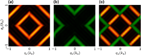
This subsection provides supporting numerical evidence for the main-text note that “in Fig. 4(a), the observed weak connections between two BISs are contributed from the atoms initially populated outside the first Brillouin zone”. As shown in Fig. 4(a) in the main text, in addition to the two-ring band-inversion surface, we notice some weak connections between the two rings. Here, in Fig. S3, we simulate the contributions to the PPQM result based on (a) atoms initially populated in the first Brillouin zone, (b) atoms initially populated in the second Brillouin zone, and (c) atoms initially populated in the first and second Brillouin zones. Indeed, in Fig. S3(a) we observe the two-ring BIS configuration. In Fig. S3(b) and (c), we see that the atoms initially populated in the second Brillouin zone contributes to the “connections” (in green) between the two BIS rings (in orange) that reflect the ground band topology.
III.4 On the future experimental exploration of the 2D Floquet topological phase diagram
At present, Fig. 4 in the main text explores a line in the 2D Floquet topological phase diagram because the modulation angular frequency and the effective Zeeman term are linearly related. In future experiments, our system holds promise for exploring more phase regions in the 2D Floquet phase diagram. This can be realized via independent control of and the energy splitting between the and states. For example, by tuning the magnetic field independent of , the magnetic-field-induced energy splitting between and will be tunable independent of . Thus will be similarly tunable, too. Based on independent control of two parameters like and the magnetic field, our system will be capable of exploring the 2D Floquet topological phase diagram in the future.
In addition, the energy splitting between and can also be changed by choosing a different pair of spin states to act as and . For example, instead of the current choice of and , if we choose and , the magnetic-field-induced energy splitting between the two states will reverse its sign, which again makes change independent of . This method further enlarges the phase region that can be explored in the 2D Floquet phase diagram.