Majorana qubit codes that also correct odd-weight errors
Abstract
The tetron architecture is a promising candidate for topological quantum computation. Each tetron Majorana island has four Majorana zero modes, and possible measurements are constrained to span zero or two Majoranas per tetron. Such measurements are known to be sufficient for correcting so-called “bosonic errors,” which affect an even number of Majoranas per tetron. We demonstrate that such measurements are also sufficient for correcting “fermionic errors,” which affect an odd number of Majoranas per tetron. In contrast, previous proposals for “fermionic error correction” on tetrons introduce more experimental challenges.
We show that “fermionic codes” can be derived from traditional “bosonic codes” by inclusion of tetrons in the stabilizer group.
I Introduction
Topological quantum computation has garnered an increasing interest in the recent years [1, 2, 3, 4, 5, 6, 7, 8, 9, 10, 11, 12, 13, 14]. Just as topology cannot be changed by local perturbations, likewise topologically protected quantum information cannot be affected by most local errors. Some local errors can be problematic and need correction. In particular, we discuss error correction schemes for the Majorana-based tetron architecture [15, 16, 17, 18, 19], shown in Fig. 1.
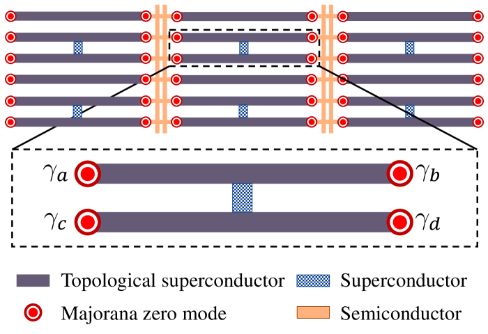
A tetron is a superconducting island, hosting four localized Majorana zero modes (MZMs), schematically shown in Fig. 2(a). One can measure the fermion parity of any operator that spans zero or two MZMs per tetron. Using such measurements, we can define stabilizer codes in a system of several tetrons. The possible errors in a tetron architecture include “bosonic” and “fermionic” errors. Bosonic errors are those which affect two MZMs per tetron, while fermionic errors affect an odd number of MZMs per tetron. Bosonic errors can be mapped to Pauli errors, and can be corrected using conventional stabilizer codes. This is not the case for fermionic errors.
Fermionic errors are typically suppressed by high charging energy. Short-lived fermionic errors relax to bosonic errors. However, a sufficiently long-lived fermionic error can disrupt measurement outcomes, and even spread to adjacent tetrons during connected measurements. Hence Ref. 18 suggests the use of “fermionic codes” that can correct fermionic errors, so that they do not spread and cause a logical error.
Although several Majorana fermionic codes have been proposed [20, 21], there exist implementation challenges specific to the tetron architecture. For example, one of the chief experimental hurdles in employing a fermionic code is the inability to directly measure the four-MZM parity of a tetron [18]. If the tetron parity were measurable, then a fermionic error could be detected. However, a measurement can overlap only two MZMs per tetron. We will show that such measurements suffice for fermionic error correction with two strategies.
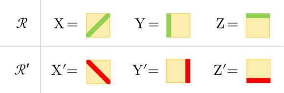
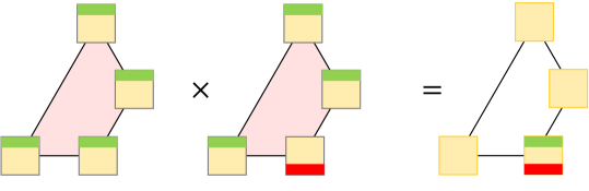
In Sec. IV, we derive fermionic error correcting codes from conventional bosonic codes such as color codes and surface codes. We introduce additional stabilizers in these codes, in which one qubit has a different Pauli to MZM operator mapping. This places the tetron in the stabilizer group, enabling fermionic error correction. Figure 3 shows an example.

Finally, in Sec. V, we study the code capacity of a fermionic code family, and provide an example of a fault-tolerant measurement scheme.
II Error correction principle
We begin with a brief introduction to general Majorana operators and general Majorana error correcting codes. Then we discuss the principles of correcting errors specific to the tetron architecture. We discuss the challenges of correcting fermionic errors, and then put forward our proposal.
II.1 Majorana operators
Consider a system with MZMs , where is even. They satisfy:
In this system, we can define a Majorana operator , which is supported on an MZM set . This Majorana operator may also be alternately represented as , where the MZM is a basis vector in . The commutation relation between two Majorana operators and is given by . However, parity measurement is only possible for Majorana operators which are supported on an even number of MZMs. Two even-weight Majorana operators commute only if they overlap on an even number of Majorana modes. The parity measurement of an even-weight Majorana operator yields either even parity (0) or odd parity (1). However, if it is affected by an error that anticommutes with , then the parity measurement of is toggled. On the other hand, if commutes with , then the parity measurement of is unaffected.
II.2 Majorana codes
The total number of MZMs in a system must be an even integer, say . They can be partitioned into MZM pairs, wherein each partitioning choice corresponds to a basis. Each MZM pair exists in a superposition of two degenerate parity eigenstates. Thus, the Majorana system has degrees of freedom and degenerate parity eigenstates.
Among these degrees of freedom, we restrict degrees of freedom by requiring that the allowed wavefunctions are eigenstates of stabilizer operators. This leaves us with degrees of freedom, wherein logical qubits can be encoded. Thus, we can form an stabilizer code, where denotes the minimum Majorana weight of all logical operators.
II.3 Tetrons
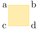
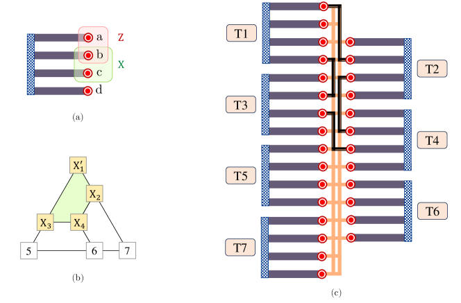
A tetron is a superconducting island with four Majorana zero modes (MZMs), maintained in an overall even parity state by high charging energy [15]. The MZMs of a tetron are denoted as , where the character denotes the MZM location according to Fig. 2(a).
A system with Majorana modes would have degrees of freedom. But if they are implemented on a tetron architecture, then degrees are restricted by the requirement of even parity on all tetrons. Thus, each tetron is left with a single degree of freedom, wherein one qubit information can be stored [3]. Each Pauli operator of this qubit has two possible representations, as shown in Fig. 2(b). For example, the Pauli operator can be represented as either or . Both of them yield the same parity measurement since the tetron has zero parity in total.
While addressing Majorana codes described on multiple tetrons, we would often use a numerical subscript to denote that Majorana operators such as or correspond to the tetron.
II.4 Bosonic and fermionic errors in tetrons
A tetron might be affected by an error that affects 1, 2, 3 or all 4 of its MZMs. An odd-weight error is said to be a fermionic error while an even-weight error is said to be a bosonic error [22]. Among these errors, the weight-4 error is trivial since it does not affect the parity of any Pauli operator. Also, a weight-3 error is equivalent to a weight-1 error, for example . So, error correction is only required for weight-2 Pauli errors and weight-1 fermionic errors.
II.5 Bosonic error correction in tetron architecture
A tetron is maintained in an overall even parity state by a high charging energy, which suppresses fermionic errors [15, 18]. As long as the charging energy preserves even parity on tetrons, only Pauli errors can occur on a tetron, and a conventional bosonic error correcting code will be sufficient to correct it.
In a system with tetrons maintained in even parity, we have degrees of freedom. We can define stabilizer operators which restrict degrees of freedom and leaves degrees for encoding logical qubits. This forms an bosonic error correcting code, where denotes the minimum qubit weight of all logical operators.
Note that each measurable Majorana operator should span zero or two MZMs per tetron, so as to preserve the even parity subspace of each tetron qubit. Parity measurement of all four MZMs of a tetron are not considered because of experimental challenges.
II.6 Challenges of fermionic error correction
If the charging energy is insufficient to prevent long-lived fermionic errors on tetrons, then we require a fermionic error correcting code. In a system with tetrons, where the tetrons are susceptible to fermionic errors, there are degrees of freedom. Thus, a fermionic error correcting code on tetrons would have parameters, where denotes the minimum Majorana weight of all logical operators.
One possible approach is to restrict degrees of freedom by introducing stabilizers, where the stabilizer is supported on the 4 MZMs of the tetron, such as in Ref. 17. The syndrome of these stabilizers would allow us to detect fermionic errors on any tetron. When coupled with syndromes of other stabilizers, it would enable us to correct both fermionic and bosonic errors affecting the Majorana code. Unfortunately, as we have previously discussed, parity measurement of all four MZMs of a tetron has turned out to be experimentally challenging [18]. A second approach involves dynamically varying the number of MZMs on an island, but that has significant experimental challenges as well [18]. Ref. 23 proposed a fermionic error correction scheme for a quantum wire, where system parameters are tuned to generate additional Majorana modes at the wire endpoints, such that stabilizers defined on these Majorana modes can correct fermionic errors. However, this can also be experimentally challenging.
II.7 Proposed fermionic error correction principle
We describe the basic principle of fermionic error correction on a single tetron. We define two complementary sets of weight-2 operators, shown in Fig. 2(b).
If a weight-2 error affects the tetron, then both sets of operators are similarly affected. For example, a weight-2 error toggles the parity of operators , while leaving the operators unaffected. This forms the building block of all bosonic error correction schemes. However, if a weight-1 error affects the tetron, then the two sets of operators are oppositely affected. For example, a fermionic error toggles the parity of and , while leaving unaffected. Conversely, the same error leaves the parity of and unaffected, while toggling the parity of . Thus, we can identify and correct a fermionic error on a tetron. This is the building block of our fermionic error correction proposal.
III Review of bosonic codes
Before moving on to fermionic error correcting codes, we shall discuss how bosonic codes may be used to deal with long-lived fermionic errors, as well as its shortcomings. Consider an bosonic code implemented on a tetron architecture, where each Pauli operator maps to a Majorana operator in [6]. This code is capable of correcting up to number of bosonic errors if no fermionic errors occur. Now suppose that the Majorana code is not only affected by bosonic errors on the tetron set , but also by fermionic errors of types in the tetron sets respectively. Observe that a fermionic error on a tetron yields the same syndromes as a bosonic error (or its equivalent) on that tetron. Thus, fermionic errors of types are identified as errors respectively, while errors are invisible. Thus, a error corresponds to a correction. Such a correction can be uniquely performed only if . If we correct a error by a correction, then we essentially shift the error from to . If a fermionic error occurs at , then it would stay there undetected. Thus, the MZM would act as a reservoir for fermionic errors at all locations of the tetron.
It might appear that the remnant errors do not affect either stabilizers or logical operators, and hence they can be left uncorrected. However, Ref. 18 notes that such uncorrected excitations may propagate from one tetron to other neighboring tetrons via connecting measurements, and finally culminate in errors of high weight. To efficiently mitigate the spread of such excitations, it recommends the usage of fermionic codes.
IV B F codes: Fermionic codes from bosonic codes
We show that a bosonic code with parameters can be translated into a fermionic Majorana code with parameters where .
IV.1 Recipe for fermionic code construction
We choose a bosonic stabilizer code from any scalable code family. We can derive a new Majorana fermion code from the stabilizers of the bosonic code. The Majorana fermion code contains several stabilizers, which we group into overlapping sets for convenience.
-
•
Set 0 contains all the stabilizers of the bosonic code, wherein every Pauli operator of the bosonic code maps to Majorana operators in .
-
•
Set contains all the stabilizers of the bosonic code, wherein Pauli operators of the qubit map to Majorana operators in , and all other Pauli operators map to Majorana operators in . Here, varies from 1 to .
Thus, we have overlapping stabilizer sets, which form a stabilizer group of rank . This stabilizer group characterizes the new Majorana fermion code with parameters.
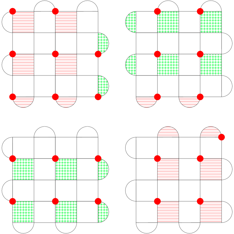
We provide an example of this scheme in Fig. 3(b), which shows the fermionic code derived from a bosonic code. Its logical qubit is characterized by .
Claim 1.
Any combination of fermionic error yields a non-zero syndrome on a Majorana fermion code.
Proof.
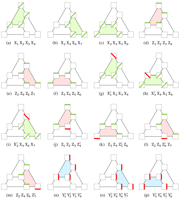
Suppose a Majorana fermion code is affected by some fermionic errors and optionally some more bosonic errors. The fermionic error would anticommute with one or more tetron operators, as they have odd intersection. The tetron operator belongs to the stabilizer group, as the tetron operator can be obtained by multiplying the independent stabilizer in set with the corresponding stabilizer in set 0, as shown in Fig. 3(c). Thus, any fermionic error would yield non-zero syndrome on a code. If the tetron is affected by fermionic error, the corresponding operators in and would yield opposite parities, and so we would measure opposite parities on the independent stabilizer of set and the corresponding set 0 stabilizer. ∎
IV.2 Code distance
In this section, we show that the derived fermionic codes have the same logical operator as the bosonic code. Hence, the fermionic code distance, or the least Majorana weight of its logical operators, is given by twice the Pauli distance of the bosonic code.
Claim 2.
If the bosonic code has parameters, then the resultant fermionic code has parameters, where .
Proof.
The bosonic code has degrees of freedom and stabilizer generators, so it has logical operators. The fermionic code has degrees of freedom, and stabilizer generators. The fermionic code has additional tetron stabilizers, as compared to the bosonic code. Thus, the fermionic code also has logical operators.
Next, we note that the logical operators in the bosonic code are also valid logical operators for the fermionic code. This is true because the set 0 stabilizers of the fermionic code are the same as the stabilizers of the bosonic code. Furthermore, each logical operator of the bosonic code can be mapped to a Majorana operator that spans 2 MZMs per tetron, and hence it commutes with each tetron stabilizer. So, the logical operators of the bosonic code satisfy all stabilizers of the fermionic code, and are the same as the logical operators of the fermionic code.
Finally, the code distance of the bosonic code is , meaning that the logical operators have a least weight of Pauli operators. Since the same set of logical operators are shared between both codes, and each Pauli operator can be mapped to 2 MZMs, so the fermionic code has code distance , where is the least Majorana weight of its logical operators. ∎
IV.3 Decoder
IV.4 Error correction on color codes
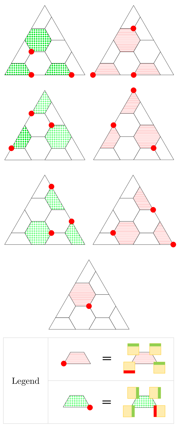
In this section, we shall discuss Majorana fermion codes derived from CSS color codes. The error correction latency of a tetron code is limited by the fact that only operators with disjoint tetron support can be parallelly measured. Although it is theoretically possible to measure two copies of the same Pauli operator on a tetron, it has been recommended that such measurements be avoided to prevent the spread of correlated errors [18]. The CSS color code based on the 6.6.6 tessellation is 3-colorable, so the corresponding set 0 stabilizers require 3 steps for measuring all X stabilizers and 3 steps for measuring all Z stabilizers.
If the Majorana fermion code is described on tetrons, then it would have independent stabilizers in addition to the set 0 stabilizers. In each of these additional stabilizers, one of the tetron operators is switched from to . These additional stabilizer syndromes can be extracted in seven steps. So, the fermionic error correction latency is 13.
-
•
The code has 13 independent stabilizers, each of which overlaps with the other, as shown in Fig. 3. Thus, one round of syndrome extraction requires 13 steps, and the error correction latency is 13.
-
•
The code has 37 independent stabilizers. Set 0 contains 9 stabilizers, 9 stabilizers, and it needs 3 + 3 steps to be measured. Sets 1 to 19 contain one independent stabilizer each, and they need 7 steps to be parallelly measured, as shown in Fig. 4. Thus, the error correction latency is 13.
-
•
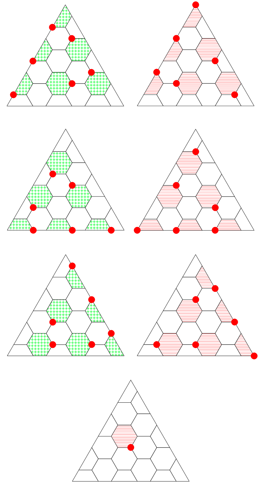
The code has 73 independent stabilizers. Set 0 contains 18 stabilizers and 18 stabilizers, and it needs 3 + 3 steps to be measured. Sets 1 to 37 contain one independent stabilizer each, and they need 7 steps to be parallelly measured, as shown in Fig. 5. Thus, the error correction latency is 13.
Before proceeding to code capacity and fault-tolerance analysis, let us see another example of this fermionic code construction recipe.
IV.5 Error correction on surface codes
In this section, we consider Majorana fermion codes derived from rotated surface codes. Its latency for fermionic error correction is 8.
If the Majorana fermion code is described on tetrons, then it would have additional independent stabilizers on top of the set 0 stabilizers. In each of these additional stabilizers, one of the tetron operators is switched from to . This defines the stabilizers for the fermionic version of the rotated surface code.
For example, let us consider the rotated surface code, shown in Fig. 6(a). From this, we derive the code, containing 49 independent stabilizers. Set 0 contains 12 stabilizers and 12 stabilizers, and it needs 2 + 2 steps to be measured. Sets 1 to 25 contain one independent stabilizer each, and they need 4 steps to be parallelly measured, as shown in Fig. 6(b). Thus, one round of fermionic syndrome extraction requires 8 syndrome measurement steps, and so the fermionic error correction latency is 8.
Thus, we have analyzed the codes, wherein the stabilizer group is generated by toggling the tetron operators at one tetron in one measurement operator at a time. The tetrons are included in the resultant stabilizer group.
V Error analysis
V.1 Code capacity
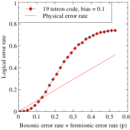
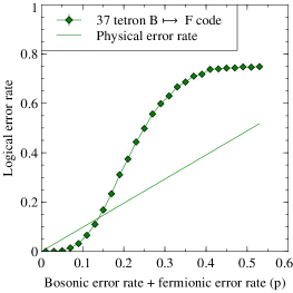
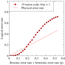
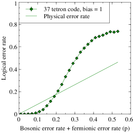
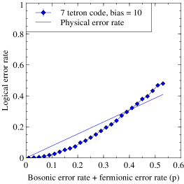
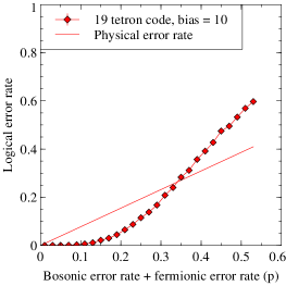
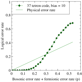
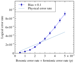
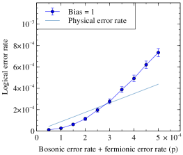
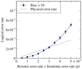
We consider a simple noise model where each tetron is subjected to bosonic errors as well as fermionic errors. If the total error rate is and the noise bias is , then the bosonic error rate is and the fermionic error rate is . As the bosonic errors X, Y, Z are equally likely, so . Similarly, the fermionic errors are equally likely, so . The physical error rate is given by since all bosonic errors affect a physical qubit, but only 3 out 4 fermionic errors affect a physical qubit on a tetron. The logical error rate for the fermionic color code family is evaluated by using the BPOSD decoder for bias values , and are plotted in Fig. 7. The corresponding variation of pseudothreshold with noise bias is shown in Fig. 8.
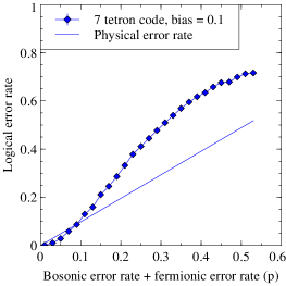
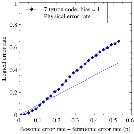
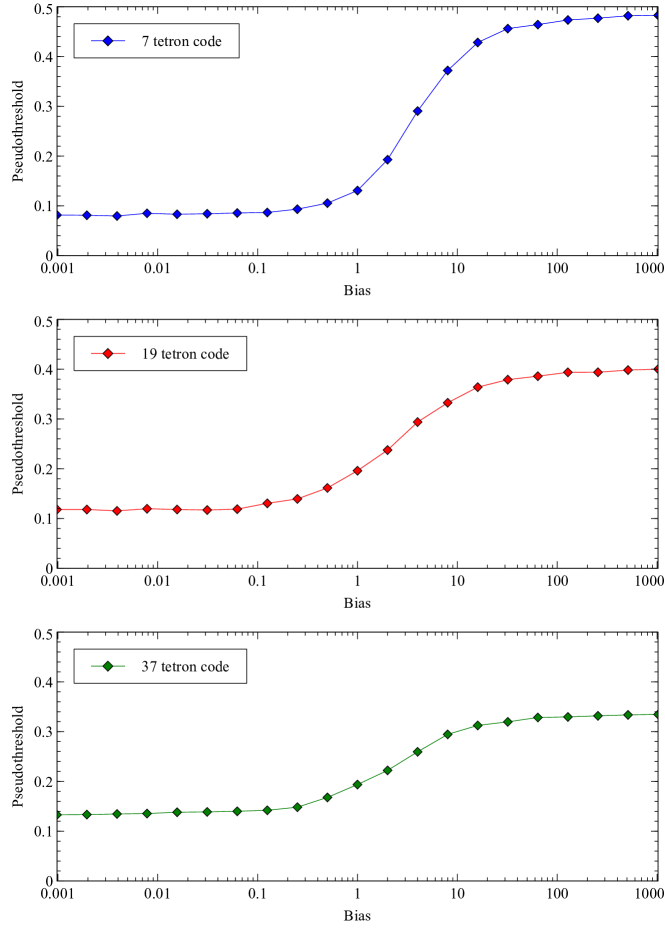
The top graph shows the variation for the 7 tetron fermionic color code.
The middle graph shows the variation for the 19 tetron fermionic color code.
The bottom graph shows the variation for the 37 tetron fermionic color code.
V.2 Fault tolerance
Fault-tolerance can be achieved by additional syndrome measurements of redundant stabilizers.
For example, Fig. 9 shows a fault-tolerant sequence for the fermionic color code, that can tolerate 1 input error or 1 intermediate error, either bosonic or fermionic. We analyze this sequence against a noise with bias, a bosonic error rate of , a fermionic error rate of , and a measurement error rate of . Figure 10 shows the existence of a fault-tolerant threshold for noise bias .
VI Conclusion
We have demonstrated that measurements spanning 2 MZMs per tetron are sufficient for fermionic error correction. We have derived a fermionic code family, by placing tetrons in the stabilizer group. Furthermore, we have generalized the construction of similar fermionic codes from conventional stabilizer codes.
The Majorana implementation of an arbitrary stabilizer code may require additional floating topological superconducting links, sometimes known as “coherent links,” for syndrome measurement [15]. The links have only 2 MZMs, so they are immune to bosonic errors, but can be affected by fermionic errors.
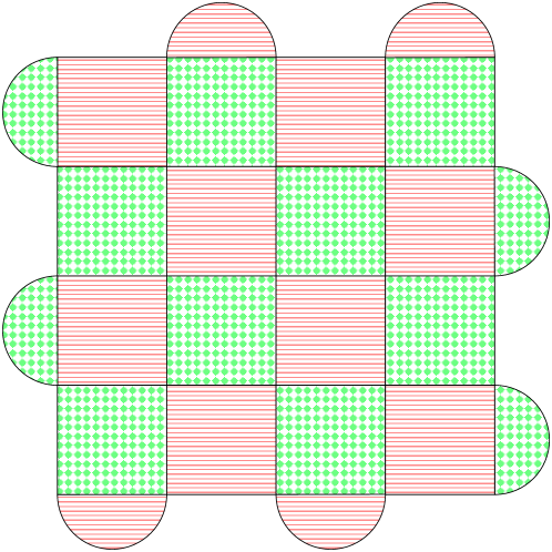
This is addressed in an upcoming work, where we show that classical error correction can be used to mitigate errors on coherent links. In addition, we also propose link-free architectures for several common stabilizer code families. For example, Fig. 11 illustrates a Majorana architecture for the code which does not require coherent links for syndrome measurement.
Acknowledgements.
This work is supported by NSF grant CCF-1254119, ARO grant W911NF-12-1-0541, and MURI Grant FA9550-18-1-0161.References
- Kitaev [2001] A. Kitaev, Unpaired Majorana fermions in quantum wires, Physics-Uspekhi 44, 131 (2001), arXiv:cond-mat/0010440 [cond-mat.mes-hall] .
- Kitaev [2003] A. Kitaev, Fault-tolerant quantum computation by anyons, Annals of Physics 303, 2 (2003), arXiv:quant-ph/9707021 .
- Kitaev [2006] A. Kitaev, Anyons in an exactly solved model and beyond, Annals of Physics 321, 2 (2006), arXiv:cond-mat/0506438 [cond-mat.mes-hall] .
- Nayak et al. [2008] C. Nayak, S. H. Simon, A. Stern, M. Freedman, and S. Das Sarma, Non-Abelian anyons and topological quantum computation, Reviews of Modern Physics 80, 1083 (2008), arXiv:0707.1889 [cond-mat.str-el] .
- Sau et al. [2010] J. D. Sau, R. M. Lutchyn, S. Tewari, and S. Das Sarma, Generic new platform for topological quantum computation using semiconductor heterostructures, Physical Review Letters 104, 040502 (2010), arXiv:0907.2239 [cond-mat.str-el] .
- Bravyi et al. [2010] S. Bravyi, B. M. Terhal, and B. Leemhuis, Majorana fermion codes, New Journal of Physics 12, 083039 (2010), arXiv:1004.3791 [quant-ph] .
- Alicea [2012] J. Alicea, New directions in the pursuit of Majorana fermions in solid state systems, Reports on Progress in Physics 75, 076501 (2012), arXiv:1202.1293 [cond-mat.supr-con] .
- Leijnse and Flensberg [2012] M. Leijnse and K. Flensberg, Introduction to topological superconductivity and Majorana fermions, Semiconductor Science and Technology 27, 124003 (2012), arXiv:1206.1736 [cond-mat.mes-hall] .
- Mong et al. [2014] R. S. K. Mong, D. J. Clarke, J. Alicea, N. H. Lindner, P. Fendley, C. Nayak, Y. Oreg, A. Stern, E. Berg, K. Shtengel, and M. P. A. Fisher, Universal topological quantum computation from a superconductor-Abelian quantum Hall heterostructure, Physical Review X 4, 011036 (2014), arXiv:1307.4403 [cond-mat.str-el] .
- Das Sarma et al. [2015] S. Das Sarma, M. Freedman, and C. Nayak, Majorana zero modes and topological quantum computation, npj Quantum Information 1, 1 (2015), arXiv:1501.02813 [cond-mat.str-el] .
- Aasen et al. [2016] D. Aasen, M. Hell, R. V. Mishmash, A. Higginbotham, J. Danon, M. Leijnse, T. S. Jespersen, J. A. Folk, C. M. Marcus, K. Flensberg, and J. Alicea, Milestones toward Majorana-based quantum computing, Physical Review X 6, 031016 (2016), arXiv:1511.05153 [cond-mat.mes-hall] .
- Lutchyn et al. [2018] R. M. Lutchyn, E. P. Bakkers, L. P. Kouwenhoven, P. Krogstrup, C. M. Marcus, and Y. Oreg, Majorana zero modes in superconductor-semiconductor heterostructures, Nature Reviews Materials 3, 52 (2018), arXiv:1707.04899 [cond-mat.supr-con] .
- Flensberg et al. [2021] K. Flensberg, F. von Oppen, and A. Stern, Engineered platforms for topological superconductivity and Majorana zero modes, Nature Reviews Materials 6, 944 (2021), arXiv:2103.05548 [cond-mat.mes-hall] .
- Aghaee et al. [2023] M. Aghaee, A. Akkala, Z. Alam, R. Ali, A. A. Ramirez, M. Andrzejczuk, A. E. Antipov, M. Astafev, B. Bauer, J. Becker, et al. (Microsoft Quantum), InAs-Al hybrid devices passing the topological gap protocol, Physical Review B 107, 245423 (2023), arXiv:2207.02472 [cond-mat.mes-hall] .
- Karzig et al. [2017] T. Karzig, C. Knapp, R. M. Lutchyn, P. Bonderson, M. B. Hastings, C. Nayak, J. Alicea, K. Flensberg, S. Plugge, Y. Oreg, C. M. Marcus, and M. H. Freedman, Scalable designs for quasiparticle-poisoning-protected topological quantum computation with Majorana zero modes, Physical Review B 95, 235305 (2017), arXiv:1610.05289 [cond-mat.mes-hall] .
- Litinski and von Oppen [2017] D. Litinski and F. von Oppen, Braiding by Majorana tracking and long-range CNOT gates with color codes, Physical Review B 96, 205413 (2017), arXiv:1708.05012 [cond-mat.mes-hall] .
- Litinski and von Oppen [2018] D. Litinski and F. von Oppen, Quantum computing with Majorana fermion codes, Physical Review B 97, 205404 (2018), arXiv:1801.08143 [cond-mat.mes-hall] .
- Knapp et al. [2018] C. Knapp, M. Beverland, D. I. Pikulin, and T. Karzig, Modeling noise and error correction for Majorana-based quantum computing, Quantum 2, 88 (2018), arXiv:1806.01275 [quant-ph] .
- Karzig et al. [2019] T. Karzig, Y. Oreg, G. Refael, and M. H. Freedman, Robust Majorana magic gates via measurements, Physical Review B 99, 144521 (2019), arXiv:1812.10498 [cond-mat.mes-hall] .
- Hastings [2017] M. B. Hastings, Small Majorana fermion codes, Quantum Information & Computation 17, 1191 (2017), arXiv:1703.00612 [quant-ph] .
- [21] S. Vijay and L. Fu, Quantum error correction for complex and Majorana fermion qubits, arXiv:1703.00459 [cond-mat.mes-hall] .
- Viyuela et al. [2019] O. Viyuela, S. Vijay, and L. Fu, Scalable fermionic error correction in Majorana surface codes, Physical Review B 99, 205114 (2019), arXiv:1812.08477 [quant-ph] .
- Bomantara and Gong [2020] R. W. Bomantara and J. Gong, Combating quasiparticle poisoning with multiple Majorana fermions in a periodically-driven quantum wire, Journal of Physics: Condensed Matter 32, 435301 (2020), arXiv:1912.03827 [quant-ph] .
- Roffe et al. [2020] J. Roffe, D. R. White, S. Burton, and E. Campbell, Decoding across the quantum low-density parity-check code landscape, Physical Review Research 2, 043423 (2020), arXiv:2005.07016 [quant-ph] .
- Roffe [2022] J. Roffe, LDPC: Python tools for low density parity check codes (2022).