CraterGrader: Autonomous Robotic Terrain Manipulation for Lunar Site Preparation and Earthmoving
Abstract
Establishing lunar infrastructure is paramount to long-term habitation on the Moon. To meet the demand for future lunar infrastructure development, we present CraterGrader, a novel system for autonomous robotic earthmoving tasks within lunar constraints. In contrast to the current approaches to construction autonomy, CraterGrader uses online perception for dynamic mapping of deformable terrain, devises an energy-efficient material movement plan using an optimization-based transport planner, precisely localizes without GPS, and uses integrated drive and tool control to manipulate regolith with unknown and non-constant geotechnical parameters. We demonstrate CraterGrader’s ability to achieve unprecedented performance in autonomous smoothing and grading within a lunar-like environment, showing that this framework is capable, robust, and a benchmark for future planetary site preparation robotics.
I Introduction
As humanity sets its sights on the Moon, Mars, and beyond, human presence requires surface infrastructure similar to the buildings and roads relied upon for millennia on Earth [1] [2]. Robotic systems show promise in constructing surface infrastructure in aerospace applications, including landing pads, roads, structural foundations, trenches, and berms, particularly in locations such as the Moon or Mars. However, the technological demands of operating in the low-mass [3], low-energy, and high-stakes environment of space require new approaches to robotic construction. Challenges such as time delays and lack of environmental awareness in teleoperation, can be overcome through increased autonomy [4]. Continuous operation time is crucial when vehicle lifetime and operationally-constrained energetics are limited. To this end, autonomy is capable of operating patiently and continuously over a 14-day lunar daylight period with minimal human supervision. Thus, there is a pressing need to develop autonomous robots that can efficiently and effectively perform lunar site preparation.
We present CraterGrader: a novel approach to autonomous robotics for lunar site preparation (Figure 1). The main contribution of this work is a combination of the following: (1) Online perception for dynamic mapping of deformable terrain, (2) Energy-efficient optimal material movement planning, (3) Fully autonomous control of simultaneous driving and tool operation, and (4) GPS-free precision robot localization subject to planetary site preparation constraints. We also discuss the experimental performance and results of the manifested robotic system, emphasizing its potential applications in lunar infrastructure development. Our work demonstrates an approach to delivering a site preparation robot that can autonomously manipulate lunar-like regolith in a worksite to form desired topography.

II Related Work
II-A Earth Moving Autonomy
Site preparation refers to the tasks that produce a baseline worksite for building foundations and superstructures. Flattening and smoothing the terrain to meet a specified planar angle, also called “grading”, is a time-intensive component of construction that requires precision. Although grading is a common task in most construction projects, there is limited research on autonomy in this area, despite significant industry interest [5].
Early work demonstrated an initial framework for intelligent earth working [6], focusing on developing a system architecture and hierarchy of the proposed concept. [7] developed an autonomous skid-steer loader, supported with a sensor suite, onboard computer, and limited supervised autonomy, highlighting the potential of an automated solution in the task of bulk material handling. Later, [8] and [9] presented a number of approaches to the dig and dump planning processes, using a 2.5D (height-field) representation of the environment to plan digging. [10] developed a robotic walking excavator, HEAP, retrofitted from a commercial excavator and demonstrated autonomy in excavation tasks, including the formation of free-form embankments. State-of-the-art systems deployed in the construction industry have focused primarily on assistive features [11] or selected subtasks within the greater construction industry [12].
Unlike terrestrial priors, our approach is energy-efficient within the constraints of lunar applications and does not rely on existing infrastructure such as GPS.
II-B Lunar Construction
The field of lunar construction and In Situ Resource Utilization (ISRU) has grown significantly in the 21st century, as the goal of a presence on the Moon has become more in reach [1]. In 2004, [13] demonstrated an initial prototype bucket wheel excavator. This was later expanded upon by the NASA Swamp Works team at Kennedy Space Center in 2010 [14], where the RASSOR platform was developed using the principle of a counter-rotating bucket drum to enable strong cutting forces with reduced weight-on-tool. Lunar site preparation was explored in 2009 during the integration of a front-facing lightweight bulldozer blade onto NASA’s Chariot platform [15].
Recently, more attention has been given to developing lightweight robotic systems [16]. In 2014, a lightweight robotic excavator was demonstrated to carry over 50% of its weight [17]. In 2018, a teleoperated platform was developed for site preparation [18] that graded and leveled a basalt rock simulated lunar worksite. A rare example of autonomy research within lunar excavation [19] focused on an evolutionary learning approach to planning, as well as ground truth localization and mapping information provided from an external source.
In 2021, a NASA Lunar Surface Technology Research (LuSTR) request for proposal (RFP) [2] outlined a desire for an autonomous lightweight system that could grade, compact, and remove rocks from a lunar worksite for a lunar landing pad. The RFP emphasized the lack of research in lunar site preparation autonomy and provided a standard reference for lunar site preparation requirements. These requirements directly inspired this project’s goals and system design, providing a framework for effective evaluation.
II-C Lunar Localization & Mapping
Localization is one of the most difficult challenges within planetary robotics due to the lack of infrastructure, harsh lighting conditions, and unknown environments. Past missions, such as the Mars Exploration Rovers, heavily relied on Visual Odometry [20] and a higher tolerance for error. Ultra-wideband (UWB) beacons are of increasing interest for Time Distance of Arrival positioning in lunar environments [21].
Other localization methods include using neural networks for global map correspondence [22] and crater landmark detection [23]. However, in the context of site preparation, relying on such landmarks for localization is not feasible as they would be inherently altered during terrain manipulation processes. [24] investigated the use of robotic total stations for line-of-sight tracking as part of a lander subsystem. A robotic total station was also used in a lunar prospector platform, Scarab [25], resulting in precise localization and robust slip estimation at 1 Hz. Strict vertical height tolerances for mapping and grading necessitate 3D positioning to a precision that is unprecedented in prior planetary robotics applications.
II-D Optimal Transport
Optimal transport refers to the problem of transforming one distribution into another using an Optimal Transport Plan, which minimizes the cost of transforming between the two distributions, also known as the Wasserstein distance. Gaspard Monge conceptualized the field of optimal transport in 1781 for transportation theory in the context of soil transport [26]. Optimal transport has practical applications in fields such as networking [27], image retrieval [28], graphics [29], and computer vision [30] [31]. An optimal transport plan represents a function map that transforms between the distributions through a minimally exertive process, analogous to mechanical work. [32] used optimal transport maps for path planning in unknown environments. The name “Earth Mover’s Distance” (EMD) was coined by Jorge Stolfi in 1994 [28] and is synonymous with the Wasserstein distance. The term “Earth Mover’s Distance” closely matches our work in a most literal sense, in which we introduce a novel application of EMD in the field of robotics and earth moving.
III System Architecture
III-A System Objective
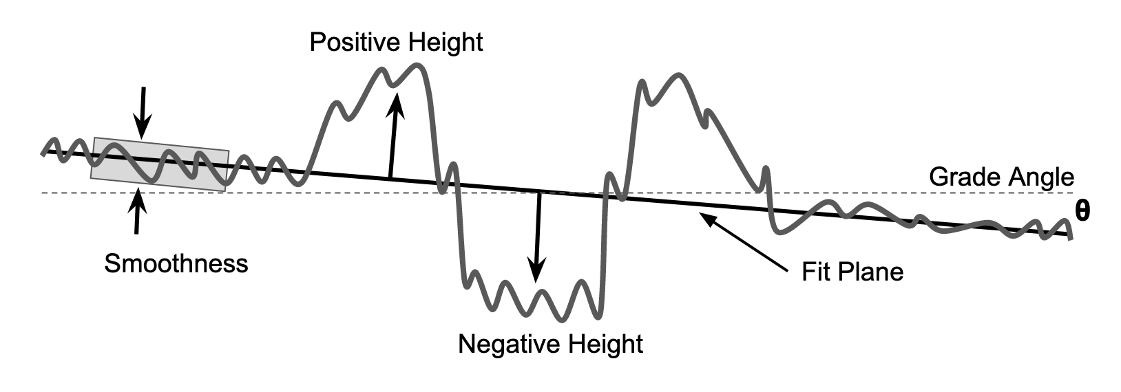
The main objective of CraterGrader is to change the local grade, absolute height, and surface smoothness for a given worksite of previously unseen lunar-like topography into the desired flat terrain topography. Here, the term grade refers to the slope, or gradient, of an assumed continuous surface topography, shown in Figure 2 alongside other terrain-based metrics. To measure the performance of the system, we derive post-operation grade, with respect to the ground plane, and smoothness requirements of and 1 cm respectively directly from the LuSTR RFP as a baseline [2]. We define an additional metric, area out-of-spec (OOS) that measures the worksite area outside of the aforementioned grade and smoothness requirements, reported as a percent reduction after autonomous operation.
The worksite is defined as a rectangular area where work is to be completed. To simplify practical operations, we assume that the worksite has obstacle-free, homogeneous terrain and no other agents or gravity offloading. The parameterization of craters in the worksite assumes a depth-to-diameter ratio of 0.2 m and a crater diameter of 1.0 m, derived from the LuSTR RFP [2], and additionally assumes that the volume of material removed from the crater is equal to the volume contained in the crater rim.
The concept of operations is as follows: CraterGrader is placed in the worksite and is given a high-level command to begin autonomous operation. This comprises an initial exploration phase, where no mapping priors are used, followed by a transport phase during which bulk material is moved while grading and smoothing, described in detail in Section IV. The robot’s autonomous operation ceases once all the transport objectives are accomplished. Additionally, the system generates a human-interpretable topographical map of the current worksite, which can be utilized for autonomous planning and also update remote human operators on grading performance and progress.
III-B Robot Platform
The robot mobility platform, illustrated in Figure 1, has a 0.5 m wheelbase and 0.43 m center-line track width, which fall within a sub-25 kg total mass. The chassis is made of aluminum extrusion and serves as the backbone for the roll-averaging rocker suspension. The wheels consist of a polymer exterior and foam core, but can be swapped with metallic wheels for flight applications. The wheels are driven through the front and rear differentials, with independent steering of the front and rear axles in a double Ackermann configuration. On flat ground, the robot produced 138 N of drawbar pull, as measured by a force transducer. The robot is powered by a rear-mounted battery system, featuring a 20 V 15.0 Ah Li-ion battery with regulation and fusing, which is sufficient for the 100 Watt maximum load on the system. At the front of the robot, a vertical mast provides mounting for various perceptual sensors, and its highest point is approximately 0.7 m from the ground.
The remaining electronics are housed in a dust-protected compartment on the top of the chassis. This compartment includes an NVIDIA Jetson AGX Xavier Development Kit as the main compute system for running the autonomy stack and integrating all peripheral sensing components. An Arduino Due board serves as a lower-level interface for the motor controllers and communicates with the Xavier over a serial connection. All compute systems utilize ROS 2 Galactic middleware to facilitate inter-process communication, with micro-ROS bridging the Xavier and Arduino Due boards.
III-C Grading Blade
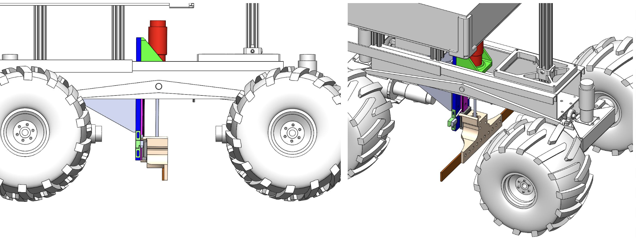
The bulk of CraterGrader’s material transport is performed by the grading blade, shown in Figure 3. The flat blade takes inspiration from terrestrial motor graders and is center-mounted for advantageous drawbar pull, a precious resource in diminished gravity as well as reduced tool gouging on pitched topography. The blade is actuated vertically and can make cuts in the terrain at specified design heights for surface grading and filling craters. This vertical degree of freedom with fast response time enables the grading blade to react dynamically to the terrain as a function of the measured slip or desired cut, and furthermore provides a fallback mechanism for escaping high-centered scenarios. Furthermore, the yaw and pitch angles of the blade can be adjusted statically to experiment with further configurations. In practice, however, maintaining a default blade orientation parallel to the vertical plane yielded the best results, enabling a configuration close to under-vehicle dozing.
III-D Drag Mat
CraterGrader features a rear-mounted chain mail drag mat, as seen in Figure 1. This drag mat effectively smooths high-frequency surface variations, utilizing a similar technique employed in sporting events to smooth terrain, such as a baseball park infield. Notably, the 316L stainless steel drag mat is essential for smoothing out impressions and tire tracks left by the robot during its traversal of the worksite. Although not applicable to all site preparation tasks, our experiments have shown that this drag mat is effective in smoothing out the terrain. Moreover, it is fully passive, simple, and flight-facing with the use of stainless steel.
III-E External Infrastructure
Testing for lunar site preparation was conducted in a 56 m2 sandbox referred to as the MoonYard (Figure 1). The MoonYard features a local network for communication between the robot, the robotic total station, and operators. The regolith simulant used during sandbox testing was fine-grained washed quartz sand with an approximate angle of repose of and bulk density of 1603 . These capabilities facilitate thorough testing and analysis of lunar excavation techniques in a simulated lunar environment.
To provide externally referenced localization estimates, the worksite utilizes a robotic total station and fiducial tags that surround the site, which act as targets for a pseudo-sun tracker. Their usage is described further in Section IV-A. An NVIDIA TX2 compute system interfaces between the robotic total station and the robot in the worksite, communicating through the local area network.
IV Autonomy
IV-A Sensing
CraterGrader’s sensing suite is designed to operate within the constraints of a lunar environment. An externally-positioned robotic total station tracks a retroreflective prism mounted to the sensing mast of the robot to provide an accurate absolute 3D position estimate with millimeter precision. We present a novel application of the robotic total station to lunar construction, inspired by research application in terrestrial site preparation [33]. This approach is motivated by the absence of GPS and a desire for site-wide consistency. The total station used is a Leica Viva TS16 robotic total station, and is modified to stream measurements at a rate of 7-10 Hz. A flight-forward approach could include a deployable external sensor payload or an additional mobile base for total station setup. A VectorNav VN-100 AHRS (Attitude and Heading Reference System) measures linear acceleration and angular velocity to generate roll and pitch angle estimates. To obtain absolute bearing measurements, sun-tracking sensors are typically used in space applications [34]. CraterGrader utilizes a pseudo-sun sensor to mimic this modality in an indoor testing environment by means of a fiducial-tracking fisheye lens camera. An Intel RealSense D435i camera is used as the primary perception sensor, which publishes point cloud information for terrain topography identification through passive stereo reconstruction. Although these sensors are not rated for space environments, their modality has been selected to best reflect the potential for future lunar sensor suites in mixed lighting conditions.
IV-B Localization
Operating in a lunar-like environment presents unique challenges for localization in that: (1) the environments are near-featureless, and (2) any prevalent features such as craters are to be destroyed during operation (with the end goal being a featureless, planar surface). Consequently, robust localization that does not rely on traditional SLAM or feature-based methods is required. The 3D pose is estimated by fusing feature-agnostic sensor measurements, including live robotic total station positioning, AHRS, pseudo-sun tracker, and onboard encoder telemetry data. Two Extended Kalman Filters (EKFs) are run in parallel to compute both an accurate global position in the map frame as well as a smooth, continuous velocity in the odometry frame, implemented via the ROS 2 robot_localization package [35]. Robot slip is estimated by comparing odometry-measured velocity relative to the absolute position as measured by the total station.
IV-C Perception & Mapping
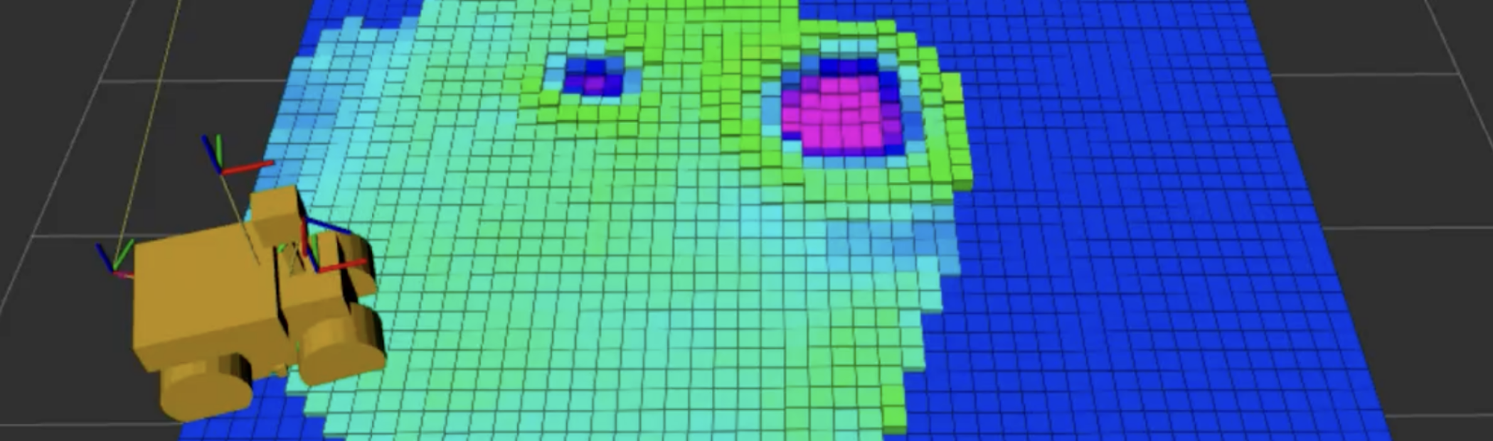
Point cloud information from stereo reconstruction and state estimates from localization are utilized to generate a 2.5D discretized map of the worksite terrain through a filter-based approach. The system transforms reconstructed 3D points into the map frame and bins them into map grid cells, where each map cell is modeled as a one-dimensional Kalman Filter, akin to [36]. This binned 2.5D map structure provides a lightweight representation of terrain topography which, compared to higher-density point cloud registration methods, is more robust to operating in an environment with sparse features. The confidence estimate of newly seen points is based on localization confidence and measurement distance from the stereo pair. After a cell has been observed a number of times, the robot is increasingly certain about the height in the grid cell until the agent disturbs it with its blade or tires. We model this as noise injection into the grid cell filters after the robot has driven over or manipulated the terrain of those cells. The resulting 2.5D grid map, seen in Figure 4, represents the expected heights at grid cell locations as seen by the robot.
IV-D Planning
The planner generates high-level task plans and calculates trajectories for tool operation and the mobility platform to manipulate the terrain based on the robot’s state and environment. At the core of the planner is the Behavior Executive, which manages system actions by interfacing with various planners and other software modules. The Behavior Executive also monitors the trajectory-following process and system health, as well as handles faults. The executive is implemented as a hierarchical finite state machine with two levels to switch between operating mode and individual action states, providing a structured approach to the planning and execution of the system’s tasks.
IV-D1 Exploration Planner
Prior to grading, a full map of initial terrain topography is necessary to perform optimal material transport planning as described in Section IV-D2. Given a rectangular worksite, the Exploration Planner generates a set of geometrically-defined waypoints to first navigate the worksite boundaries and then cover the center, to ultimately achieve full map coverage. This strategy proved to be more feasible for the robot’s kinematics and large turning radius, compared to other approaches such as a naive raster pattern.
IV-D2 Transport Planner
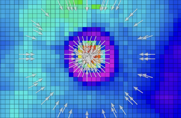
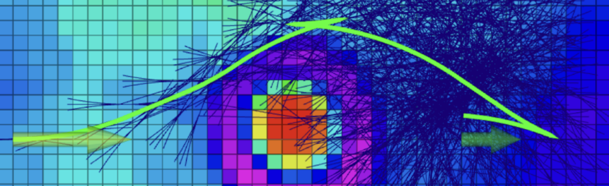
The Transport Planner calculates which highs of the worksite should be pushed to which lows to convert an arbitrary starting worksite topography to an arbitrary final design topography. This approach was selected instead of motion parameterized by crater geometry to robustly handle malformed craters (as created during operation). Within the context of grading craters, a design topography was created as a flat plane so the result was a transport plan to pair waypoints along the crater rim (highs, referred to as sources) to waypoints along the crater floor (lows, referred to as sinks), with an associated material transport volume. An example transport plan for a single crater is depicted in Figure 5.
The planner is modality-agnostic. Its input is the live 2.5D map for the starting topography and a static design 2.5D map defining the desired final topography. Each map cell is used as a node, where the th node is defined by planar coordinates with associated source volume or sink volume (analogous to height with constant grid size). Nodes with higher height in the live map than the static design map are put in a source set of size , and nodes with lower height are put in the sink set of size . To simplify the optimization formulation, all volumes are defined as positive within their respective sets.
The planner is centered on a mixed integer linear program (MILP) that solves the problem of minimal-energy terrain manipulation to convert an unstructured topography to a design topography. The optimization is based on an earth mover’s distance (EMD) optimization problem, which determines volumes to move between source and sink node pairs, minimizing the total sum of volume moved multiplied by the distances traveled; analogous to mechanical work ignoring transport rate.
The final optimization formulation is given by Eq. 1-8, where the binary decision variable is selected based on the relative source and sink total volumes so the problem only needs to be solved once. is a distance matrix between source and sink node coordinates, and and are vectors containing source and sink volumes, respectively. Full derivation details can be found in the APPENDIX.
The planar coordinates for the pairs of source and sink nodes computed in the transport plan are then used as trajectory waypoints, with the heading aligned to the minimum distance vector between the two waypoints. A third waypoint with the same heading is offset to the rear of the source node to help simplify motion planning, guiding the system to drive in and out of the crater when moving between source and sink pairs. These three waypoints are combined into a transport triplet ordered with the offset waypoint first, then the source node, and then the sink node.
Adjustments were made to improve online computational efficiency. First, thresholding was applied to ignore source and sink nodes with height/volume that were considered already close enough to the design topography. Second, in the observation that the grading blade can push more than one cell, a decimation filter was applied to the source nodes to enforce a minimum Euclidean distance between the planar coordinates when the waypoint headings were also within a threshold. These two techniques effectively reduced the number of total nodes to decrease the size of the optimization problem and speed up online computation. The threshold parameters were tuned for the anticipated crater size and grading blade width.
After solving the optimization problem online, the Behavior Executive then radially orders the transport triplets and feeds the waypoints in each triplet incrementally to the Kinematic Planner (Section IV-D3) to calculate the following trajectories.
| (1) | ||||||
| s.t. | (2) | |||||
| (3) | ||||||
| (4) | ||||||
| (5) | ||||||
| (6) | ||||||
| (7) | ||||||
| (8) | ||||||
where
IV-D3 Kinematic Planner
The Kinematic Planner includes a lattice generator, an A* search algorithm [37], and tool and velocity planners. The lattice generator creates kinematically feasible path candidates, and A* is used to find a path within position and heading thresholds of a goal pose, as seen in Figure 6. Path candidates are assigned A* cost according to weighted topography cost and cumulative distance, with a heuristic of Euclidean distance between the terminal path position to the goal. The topography cost results in path solutions that minimize climbing heights to mitigate the risk of becoming high-centered during navigation. To improve online search efficiency, the heuristic was iteratively weighted to bias the search toward finding feasible solutions within online time constraints.
The velocity planner assigns a target velocity to each waypoint along the path, depending on whether the robot is traveling forward or backward. Finally, the tool planner assigns a target blade height to each waypoint using a heuristic further explained in Section IV-E. By integrating these planners, the kinematic planner can generate optimized and feasible trajectories for the robot to execute.
IV-E Trajectory Control
The trajectory controller generates actuator commands for three objectives: steering, driving, and tool motion. Each of these objectives has its own specific controller. The steering controller, based on the Stanley control law [38], calculates the steer angle that can reduce and trade-off cross-track and heading error. The driving controller penalizes the driving velocity based on the steer speed and applies clamping and low-pass filters. Finally, the tool controller adjusts the tool position when the robot is either backing up or going forward to minimize undesired drag forces. The controller moves the tool down to a set height when going forward and up to an unobstructing height when backing up.
V Experimental Results
V-A Test Setup
Testing was performed at the MoonYard described in Section III-E, serving as an analog to lunar landscapes of interest for infrastructure development. Worksite terrain was initially prepared by manually smoothing to a grade within , followed by digging a 1 m diameter crater near the center of the worksite, using a mold to create identical craters for repeatable testing.
During evaluation, CraterGrader was placed into the prepared MoonYard. Fully autonomous mapping and grading operations, described in Section III-A, were executed for an approximately 30-minute period, whereupon the robot was removed for worksite verification.
Verification was performed by capturing high-resolution point cloud scans before and after autonomous operation. A FARO Focus 3D laser scanner generated scans of worksite terrain accurate to millimeter precision, which were processed offline in an open-source 3D data analysis software. Out-of-worksite data points were removed from the point cloud and a ground plane was fitted from the remaining points. The data was then exported to an analysis pipeline to compute validation metrics such as surface grade, smoothness, and area OOS reduction.
V-B Results
System performance was evaluated across five 30-minute trials of end-to-end autonomous operation, including a live demonstration for the Carnegie Mellon University Robotics Institute. Average performance results for the four evaluation trials are shown in Table I, and results for the live performance are depicted in Table II. The key metrics to measure performance are selected as worksite grade, worksite smoothness, and area OOS reduction.
On average, CraterGrader achieved a worksite grade of 0.11 and smoothness of 0.7 cm. In a culminating live demonstration for a viewing audience, CraterGrader achieved 0.07 grade and 0.6 cm smoothness. In all cases, CraterGrader is able to repeatably produce a smoothly graded worksite that meets the desired NASA baseline requirements in [2].
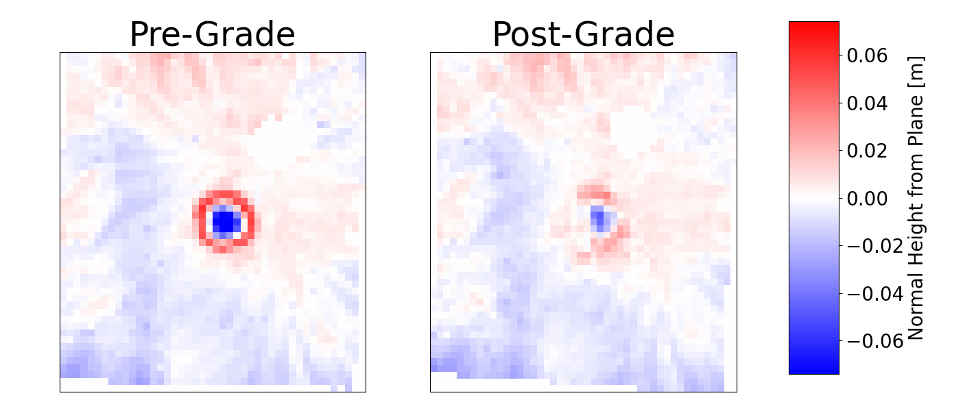
The area OOS reduction metric captures the essence of CraterGrader’s ability to manipulate unstructured terrain, and transform it into a worksite that meets a set of desired specifications. On average, CraterGrader achieved an 88% reduction in area OOS (from 0.45 m2 to 0.05 m2) for all four evaluation trials. CraterGrader also achieved an 82% reduction in area OOS (from 0.45 m2 to 0.08 m2) during the live demonstration, measured from the average starting conditions of the prior evaluation trials. Figure 7 illustrates an example worksite terrain topography from the evaluation trials, both pre- and post-grade, in which the prominent crater feature was flattened after autonomous operation.
| Metric | Desired | Pre-Grade | Post-Grade |
|---|---|---|---|
| Worksite Grade | 0.12° | 0.11° | |
| Worksite Smoothness | 1 cm | 1.25 cm | 0.7 cm |
| Area OOS Reduction | N/A | N/A | 88% |
| Metric | Desired | Post-Grade |
|---|---|---|
| Worksite Grade | 0.07° | |
| Worksite Smoothness | 1 cm | 0.6 cm |
| Area OOS Reduction | N/A | 82% |
VI Conclusions and Future Work
CraterGrader is a novel approach for modifying unstructured terrain to achieve a desired topography with planetary robotics constraints in mind. Unstructured and continuously deforming terrain is perceived and dynamically mapped, leveraging precision GPS-free localization subject to lunar constraints. Tool and motion planning is performed by calculating a transport plan online using a mixed integer linear program formulation of earth mover’s distance and then executed with tool, drive, and steer control.
This work aims to inform future planetary site preparation autonomy development, in addition to any terrestrial applications which may benefit from similar levels of autonomy. The demonstration of our low-mass rover has shown that this approach is feasible, robust to uncertain dynamics and measurements, and well-suited to autonomous site preparation and earthmoving for a lunar environment. This represents a significant step toward the future of autonomous robots for lunar site preparation and intelligent, energy-efficient terrain manipulation in general. Future work could include introducing additional modalities of earthmoving tasks such as rock picking, compaction, drilling, blasting, etc. to create a more versatile machine. It is also in the interest of the authors to extend the work of the machine-agnostic transport planner to other heterogenous robotic vehicles for material transport which could take the form of a scraper, bulldozer, backhoe, excavator, loader, or dump truck, possibly in multi-agent applications.
APPENDIX
The Transport Planner MILP is derived by the following, as introduced in Section IV-D2. Again, the planner uses nodes where the th node is defined by planar coordinates with associated source volume or sink volume within a worksite. A set of source nodes of size and sink nodes of size are defined with volumes above and below a design topography at their respective locations, with all volumes positive within their sets.
The optimization solves for an optimal transport map assigning volume transport from source node to sink node over the associated length from the pairwise Euclidean distance matrix . All transport volumes are constrained to be positive, resulting in the objective function Eq. 1 with variable constraint Eq. 2.
The volumes transported between nodes are constrained by the total amounts of source and sink volumes. In practice, these volume quantities are likely to be unequal due to underlying site topography or because of mapping inaccuracies. One simple, minimal work approach is to design constraints that can ignore some volume from the larger of the source and sink volumes. A ones vector denoted filters the assigned transport volume for an associated node against the volumes in all other nodes, denoted by vectors for source and sink volumes such that either the source volume is exhausted to fill all sink volume , so or the sink volume is completely exhausted to utilize all source volume , so . To ensure that one of the total volumes is completely exhausted, the maximum of the two cases must be equal to zero.
| (9) |
This maximization can be converted to mixed integer linear programming constraints using the “big-M” method where is defined as the maximum of the two volumes with binary decision variable when the source is less than sink volume , and otherwise.
First, the maximization can simply be upper bounded by zero to ensure the assigned transport in from the source or sink set never exceeds the available volume, seen in Eq. 3-4.
Next, the big-M formulation can be used to create lower bounds. In the first case when source is less than sink, the quantity will be negative to a maximum of which in this case will be . So we have the following lower bound on the remaining sink volume:
| (10) |
In the second case when source is greater than or equal to sink, the remaining source quantity will similarly be negative and bound by the maximum available source , which by definition of this case is again :
| (11) |
Note that in the first case , the source will be fully utilized so constraint Eq. 11 will be zero with constraint Eq. 10 being slack. In the second case the sink will be fully utilized so constraint Eq. 10 will be zero with constraint Eq. 11 being slack. Since the case is dependent only on the total source and sink volumes, we can improve online computation efficiency by solving for the optimal binary decision variable and intermediate variable online prior to optimizing by comparing the total volumes, as in Eq. 7-8.
ACKNOWLEDGMENT
We would like to give special thanks to Dr. John Dolan, Warren “Chuck” Whittaker, Dr. Dimitrios Apostolopoulos, Dr. David Wettergreen, and the MRSD (Master of Science in Robotic Systems Development) program of the Carnegie Mellon University Robotics Institute for their support, opinions, and advice throughout this journey.
References
- [1] (2020) Nasa’s plan for sustained lunar exploration and development. [Online]. Available: https://www.nasa.gov/sites/default/files/atoms/files/a˙sustained˙lunar˙presence˙nspc˙report4220final.pdf
- [2] NASA, “Space technology research grants program, lunar surface technology research opportunities appendix,” NASA NSpires, 2021.
- [3] K. Skonieczny, D. Wettergreen, and W. Whittaker, “Advantages of continuous excavation in lightweight planetary robotic operations,” The International Journal of Robotics Research, vol. 35, no. 9, pp. 1121–1139, 2016. [Online]. Available: https://doi.org/10.1177/0278364915615689
- [4] D. P. Miller and K. Machulis, “Visual aids for lunar rover tele-operation,” in proceedings of 8th International Symposium on Artificial Intelligence, Robotics and Automation in Space, edited by R. Battrick, ESA Publishing, Noordwijk, Netherlands, 2005.
- [5] N. Melenbrink, J. Werfel, and A. Menges, “On-site autonomous construction robots: Towards unsupervised building,” Automation in Construction, vol. 119, p. 103312, 2020. [Online]. Available: https://www.sciencedirect.com/science/article/pii/S0926580520301746
- [6] S.-K. Kim and J. S. Russell, “Framework for an intelligent earthwork system: Part i. system architecture,” Automation in Construction, vol. 12, no. 1, pp. 1–13, 2003. [Online]. Available: https://www.sciencedirect.com/science/article/pii/S0926580502000341
- [7] A. Bonchis, N. Hillier, J. Ryde, E. Duff, and C. Pradalier, “Experiments in autonomous earth moving,” IFAC Proceedings Volumes, vol. 44, no. 1, pp. 11 588–11 593, 2011, 18th IFAC World Congress. [Online]. Available: https://www.sciencedirect.com/science/article/pii/S1474667016454777
- [8] J. A. Marshall, P. F. Murphy, and L. K. Daneshmend, “Toward autonomous excavation of fragmented rock: Full-scale experiments,” IEEE Transactions on Automation Science and Engineering, vol. 5, no. 3, p. 562 – 566, 2008.
- [9] D. Schmidt, M. Proetzsch, and K. Berns, “Simulation and control of an autonomous bucket excavator for landscaping tasks,” in 2010 IEEE International Conference on Robotics and Automation, 2010, pp. 5108–5113.
- [10] D. Jud, S. Kerscher, M. Wermelinger, E. Jelavic, P. Egli, P. Leemann, G. Hottiger, and M. Hutter, “Heap - the autonomous walking excavator,” Automation in Construction, vol. 129, p. 103783, 2021. [Online]. Available: https://www.sciencedirect.com/science/article/pii/S092658052100234X
- [11] Caterpillar. (2023) Cat grade with 3d for dozers. [Online]. Available: https://www.cat.com/en_US/products/new/technology/grade.html
- [12] B. Robotics. (2023) Everest, autonomy at your fingertips. [Online]. Available: https://www.builtrobotics.com/technology/everest
- [13] T. Muff, L. Johnson, R. King, and M. Duke, “A prototype bucket wheel excavator for the moon, mars and phobos,” in AIP conference proceedings, vol. 699, no. 1. American Institute of Physics, 2004, pp. 967–974.
- [14] J. Schuler, J. Smith, R. Mueller, and A. Nick, “Rassor, the reduced gravity excavator,” Lunar ISRU 2019, Developing a New Space Economy through Lunar Resources and Their Utilization, 5061, abstract, 2019.
- [15] R. Mueller, J. Schuler, A. Nick, A. Wilkinson, C. Gallo, and R. King, “Lightweight bulldozer attachment for construction and excavation on the lunar surface,” in AIAA SPACE 2009 conference & exposition, 2009, p. 6466.
- [16] K. Skonieczny, D. Wettergreen, and W. R. Whittaker, “Parameters governing regolith site work by small robots,” in Earth and Space 2010: Engineering, Science, Construction, and Operations in Challenging Environments, 2010, pp. 1326–1333.
- [17] K. Skonieczny, M. Delaney, D. Wettergreen, and W. Whittaker, “Productive lightweight robotic excavation for the moon and mars,” Journal of Aerospace Engineering, vol. 27, 07 2014.
- [18] R. Kelso, R. Romo, C. Andersen, R. Mueller, T. Lippitt, N. Gelino, J. Smith, I. I. Townsend, J. Schuler, M. Nugent, et al., “Planetary basalt field project: Construction of a lunar launch/landing pad, pisces and nasa kennedy space center project update,” in Earth and Space 2016: Engineering for Extreme Environments. American Society of Civil Engineers Reston, VA, 2016, pp. 653–667.
- [19] J. Thangavelautham, K. Law, T. Fu, N. A. El Samid, A. D. Smith, and G. M. D’Eleuterio, “Autonomous multirobot excavation for lunar applications,” Robotica, vol. 35, no. 12, pp. 2330–2362, 2017.
- [20] Y. Cheng, M. Maimone, and L. Matthies, “Visual odometry on the mars exploration rovers,” in 2005 IEEE International Conference on Systems, Man and Cybernetics, vol. 1. IEEE, 2005, pp. 903–910.
- [21] H. Jiang, X. Sun, and X. Yan, “Lunar rover positioning based on time of arrival measurements of uwb signals,” in 2008 4th International Conference on Wireless Communications, Networking and Mobile Computing. IEEE, 2008, pp. 1–4.
- [22] B. Wu, P. Ludivig, R. Potter, A. Chung, and T. Seabrook, “Absolute localization for surface robotics in gps-denied environments using a neural network.” in International Symposium on Artificial Intelligence, Robotics and Automation in Space, 2020, 2020.
- [23] L. Matthies, S. Daftry, S. Tepsuporn, Y. Cheng, D. Atha, R. M. Swan, S. Ravichandar, and M. Ono, “Lunar rover localization using craters as landmarks,” in 2022 IEEE Aerospace Conference (AERO), 2022, pp. 1–17.
- [24] P. Molina, P. Iles, and K. MacTavish, “Lander-based localization system of the lunar analogue rover “artemis”,” in International Symposium on Artificial Intelligence, Robotics and Automation in Space, 2012, pp. 4–6.
- [25] D. Wettergreen, S. Moreland, K. Skonieczny, D. Jonak, D. Kohanbash, and J. Teza, “Design and field experimentation of a prototype lunar prospector,” The International journal of robotics research, vol. 29, no. 12, pp. 1550–1564, 2010.
- [26] G. Monge, “Mémoire sur la théorie des déblais et des remblais,” Mem. Math. Phys. Acad. Royale Sci., pp. 666–704, 1781.
- [27] M. Burger, I. Humpert, and J.-F. Pietschmann, “Dynamic optimal transport on networks,” 2021. [Online]. Available: https://arxiv.org/abs/2101.03415
- [28] Y. Rubner, C. Tomasi, and L. J. Guibas, “The earth mover’s distance as a metric for image retrieval,” International journal of computer vision, vol. 40, no. 2, p. 99, 2000.
- [29] J. Solomon, R. Rustamov, L. Guibas, and A. Butscher, “Earth mover’s distances on discrete surfaces,” ACM Transactions on Graphics (ToG), vol. 33, no. 4, pp. 1–12, 2014.
- [30] C. Gottschlich and S. Huckemann, “Separating the real from the synthetic: minutiae histograms as fingerprints of fingerprints,” IET Biometrics, vol. 3, no. 4, pp. 291–301, 2014.
- [31] E. Ricci, G. Zen, N. Sebe, and S. Messelodi, “A prototype learning framework using emd: Application to complex scenes analysis,” IEEE Transactions on Pattern Analysis and Machine Intelligence, vol. 35, no. 3, pp. 513–526, 2013.
- [32] H. Zhai, M. Egerstedt, and H. Zhou, “Path planning in unknown environments using optimal transport theory,” 2019. [Online]. Available: https://arxiv.org/abs/1909.11235
- [33] S. Garlinge, D. Mares, and D. O’Shaughnessy, “3d positioning systems for underground construction robots,” in Association of Public Authority Surveyors Webinar Series. APAS, 2020.
- [34] P. Furgale, J. Enright, and T. Barfoot, “Sun sensor navigation for planetary rovers: Theory and field testing,” IEEE Transactions on Aerospace and Electronic Systems, vol. 47, no. 3, pp. 1631–1647, 2011.
- [35] T. Moore and D. Stouch, “A generalized extended kalman filter implementation for the robot operating system,” in Intelligent Autonomous Systems 13, E. Menegatti, N. Michael, K. Berns, and H. Yamaguchi, Eds. Cham: Springer International Publishing, 2016, pp. 335–348.
- [36] L. B. Cremean and R. M. Murray, “Uncertainty-based sensor fusion of range data for real-time digital elevation mapping (rtdem),” in Proceedings of the IEEE International Conference on Robotics and Automation, 2005, pp. 18–22.
- [37] P. Hart, N. Nilsson, and B. Raphael, “A formal basis for the heuristic determination of minimum cost paths,” IEEE Transactions on Systems Science and Cybernetics, vol. 4, no. 2, pp. 100–107, 1968. [Online]. Available: https://doi.org/10.1109/tssc.1968.300136
- [38] G. M. Hoffmann, C. J. Tomlin, M. Montemerlo, and S. Thrun, “Autonomous automobile trajectory tracking for off-road driving: Controller design, experimental validation and racing,” in 2007 American control conference. IEEE, 2007, pp. 2296–2301.