Experimental Demonstration of Coupled Learning in Elastic Networks
Abstract
Coupled learning is a contrastive scheme for tuning the properties of individual elements within a network in order to achieve desired functionality of the system. It takes advantage of physics both to learn using local rules and to “compute” the output response to input data, thus enabling the system to perform decentralized computation without the need for a processor or external memory. We demonstrate a proof-of-concept mechanical network that can learn simple tasks such as self-symmetrizing via iterative tuning of individual spring rest lengths. These mechanical networks could feasibly be scaled and automated to solve increasingly complex tasks, hinting at a new class of “smart” metamaterials.
I Introduction
Learning is a physical process by which a system evolves to exhibit a desired behavior. Artificial neural networks have been very successful in training towards a wide array of tasks including regression and classification via global optimization algorithms such as gradient descent [1]. These algorithms generally rely on a central processor to use global information about the state of the entire network and compute gradients to determine how the system should evolve in the next training step. By contrast, physical and biological learning systems generally do not have access to such global information as they evolve, and so must instead rely on a decentralized learning scheme to achieve desired behaviors [2]. In such systems, learning is better described as an emergent phenomenon in a complex material. Decentralized, local learning as seen in biological systems has advantages over the computational approach [3], including power efficiency [4], scalability of processing speed with network size [5], and robustness to damage [6].
Recent efforts have been made to develop algorithms inspired by computational machine learning for implementation in physical systems [7], adopting some of the features exhibited in biological systems and using physics to propagate information throughout the system. Such approaches involve tuning the individual properties of a collective material using global information, e.g. by backpropagation [8]. Directed aging [9] is a learning algorithm in which a network minimizes its elastic energy in response to stress. Contrastive learning compares a network’s internal state in response to different sets of boundary conditions [10, 11] and takes advantage of local rules to perform updates [12]. Equilibrium propagation is a class of algorithms which combine the locality of contrastive learning with the physics-informed update rules of directed aging [13, 14, 15]. Coupled learning similarly trains a network by applying boundary conditions, “nudging” the network into the desired functionality via local learning rules [16].
Despite the growing interest for learning behaviors in physical materials, laboratory realizations are still rare. Pruning bonds in a network is one approach to achieve some desired functionality [17, 18, 12], but this process is generally not reversible. Directed aging has been effectively demonstrated in a laboratory setting [19, 12, 9], but this algorithm does not minimize the true loss function and is therefore limited in its use cases. It is also possible to computationally simulate a network’s training and print it out in its trained state [20], but there are good reasons to build a network with tunable components: A printed network that has been designed for a single task is static in nature, and could not be re-trained for alternative behavior after printing. Additionally, the distributed learning algorithm is agnostic to manufacturing errors and a physical network could use this algorithm to re-learn a task after taking damage. Equilibrium propagation has been shown to successfully train an Ising machine [21]. Coupled learning has been demonstrated in the lab for electrical flow networks [22, 23, 24] to learn various tasks, including classification.
In comparison with flow networks, a mechanical network poses unique and complex challenges for construction. The degrees of freedom in a mechanical network are vectorial in nature, rather than scalar like the voltages at nodes of a circuit, which increases the dimensional complexity of the system. A mechanical network is spatially embedded, so the architecture and connectivity of the network must be carefully chosen for proper coordination number and to avoid collision of neighboring edges and frustration. Construction of a unit cell with adjustable learning degrees of freedom is of primary concern as well. Lee et al. [25] have constructed and trained a network of elastic components with tunable stiffnesses using voice coils, although their approach still relies on a central processor to compute updates globally. Tunable elastic components built from a combination spring-pendulum system can perform unsupervised pattern-finding tasks [26], but functionality in unsupervised training is limited to a relatively small subset of potential problems of interest [27]. Arinze et al. used autonomous softening of hinges to train thin elastic sheets to fold in desired ways in response to force patterns [28] based on a local supervised learning rule that softens elements only when they fold correctly [29].
In this paper, we tune each edge’s rest length, rather than its stiffness. Using rest length as the learning degree of freedom requires special consideration, as each iterative learning step will alter the equilibrium state of the network. Additionally, unlike bond stiffnesses that are directly analogous to conductances in flow networks, the rest length has no direct analogy and is unique to mechanical systems. In our approach, a turnbuckle is connected to a Hookean spring at its end, and by adjusting the length of the turnbuckle, the effective rest length of combination spring-turnbuckle edge is altered. Since updates are not automated but rather made manually, it is imperative to choose architectures that minimize the number of tunable edges while still exhibiting a diversity of tunable behaviors. Here we provide two laboratory demonstrations of experimental mechanical systems that can train using coupled learning with adjustable rest length components, and we compare with simulation. Our systems can optimize for a generic task without the use of a computer, placing them among the first supervised local learning demonstrations in physical mechanical systems. The two minimal architectures presented in this study have been shown to effectively span the range of possible states to achieve the desired behavior quickly, smoothly, and effectively. Further, our experimental demonstrations exhibit successful learning behaviors that are not accounted for by simulation, thus lending credence to the robustness of our algorithm. The success of these initial experiments shows promise for scalable learning networks in more complex systems.
II Coupled Learning for Spring-Turnbuckle Systems
We construct a mechanical network such as the one depicted in Fig. 1(a). Each edge of this network is an extension spring with the same stiffness and rest length connected to a rigid turnbuckle with adjustable length , as drawn schematically in the inset of Fig. 1(a). The total node-node separation of the edge, including the length of the rigid part, is , such that the spring’s extension past its rest length is . The mechanical energy associated with this edge is given by Hooke’s law as
| (1) |
The total mechanical energy in the network is the sum of the elastic energies of all edges,
| (2) |
and serves as the “physical cost function” which the system automatically minimizes subject to the imposed boundary conditions.
We wish to train this network to achieve some desired behavior in the positions of its nodes. This is what is referred to as a “motion task.” We select certain nodes to be “inputs” and “outputs” for our task, depicted in Fig. 1(a) as blue and red filled circles, respectively. When the input node is at position , we want the output node’s position to be at some desired value, .
We train for this behavior by iteratively adjusting the turnbuckle lengths at each edge according to the coupled learning algorithm [16]. Here, the positions of each node in the system serve as the “physical degrees of freedom,” which equilibrate so that there is no net force on each edge, while the adjustable rest lengths act as the “learning degrees of freedom” to be adjusted during training. In the free state, Fig. 1(a), we apply the input boundary condition to the network by fixing the position of the input node, , and allowing all other physical degrees of freedom to equilibrate. The output node’s position is measured, along with the extensions of each edge in the network, . In the clamped state, Fig. 1(b), we once again apply the input boundary condition, but now we also enforce a fixed value for the position of the output node by “nudging” it towards the desired position . The clamped output value generally takes the form
| (3) |
where the “nudge factor” is a hyperparameter of the training scheme. In all experiments below, we take a full nudge of so the output node is clamped at the desired position at each learning step. The lengths of each edge in this state are also recorded.
In coupled learning, the system evolves by comparing the mechanical energy of the network in the free and clamped states. Learning is achieved when the energy in the clamped state is equal to the energy in the free state . In the absence of nonlinear mechanical effects like buckling, the difference between these energies, which we refer to as the “learning contrast function”, is always non-negative because the clamped state is more strongly constrained than the free state, . Analogous to the machine-learning approach of minimizing a loss function like mean-squared error (MSE), the rest lengths evolve by descending along the gradient of the contrast function:
| (4) | |||||
| (5) | |||||
| (6) |
Since the learning contrast function was not squared, the partial derivative in Eq. (4) picks out only the term, which is readily simplified to Eq. (6) using Eq. (1). Thus, we arrive at the following general discrete learning rule for how to update each edge at each training step for any network of identical spring-turnbuckle edges:
| (7) |
where is a per-step learning rate that we shall set in experiment, and is the difference in clamped and free lengths of the edge being updated. This simple rule is purely local: each edge is updates according only to it’s behavior, irrespective of how other edges change upon clamping. As discussed below, we train with different learning rate parameters in the range . Iterative updates should drive the global learning contrast function to zero in order to achieve the desired motion function.
While our Eq. (7) update rule is spatially local, it is not temporally local because the learning rule requires simultaneous information about the system in two states. The experimental implementation in an electrical resistor network [22] was able to circumvent this issue by building identical twin networks to run the free and clamped states simultaneously. By contrast, the mechanical network is embedded in space, posing difficulties for constructing twin 2-dimensional networks side-by-side, and an impossibility entirely for 3-dimensional implementations. Therefore, our approach must rely on temporal memory of the spring extensions between the free and clamped states.
III Motion Divider
Analogous to the voltage divider in the electrical network case, our first demonstration is a “motion divider” network, or two tunable-rest length springs connected in series. A photograph of the network is shown in Fig. 2(a). We construct the network so it is hanging vertically under gravity from a fixed point, thereby restricting the motion to be along the axis of gravity. We define the one-dimensional position to be at the fixed hanging point, and measures position downwards from this origin. The first spring is connected to the fixed point via a turnbuckle of length , terminating at position . The second turnbuckle of length then connects to the second spring, which terminates at position . We choose to be the input node of our system and to be the output node. Both springs have equal stiffnesses and natural rest lengths , so that the Eq. (7) learning rule applies. The forces acting on springs in series are equal, so holds and can be solved for the output node position as
| (8) |
where . Choosing some desired numerical value for defines a trainable task for our system. This is equivalent to a machine-learning linear regression problem with one variable coefficient [30]. Note that there is no unique solution for and ; only their difference is trained for. Like typical machine learning algorithms, our system is over-parameterized and thus has multiple solutions.
III.1 Apparatus
Each unit cell of our network consists of an extension spring coupled to a turnbuckle in series, as shown diagrammatically in Fig. 1 and photographically in Fig. 2(a). The spring has a stiffness of and a rest length of (Grainger 5108N536), while the turnbuckle has a range of lengths between and (eoocvt M4 Stainless Steel 304). Updates are made on the system via turns of the turnbuckle, where each half-turn results in a change in length of . The total effective rest length of the unit cell object is therefore . These unit cells are connected together using keyrings, which serve functionally as the nodes of our network. The system is clamped at the nodes manually by inserting a small rod through the keyrings and fixing its position up or down using a clamp on a vertical pole. Measurements were made manually by the experimenter using a ruler.
III.2 Results
Fig. 2(b) shows the evolution of the node couplings over the course of training. The network is trained multiple times to achieve different values for the goal state, . The turnbuckle lengths were not reset after each training; instead, the network was able to re-learn a new task without initialization. The evolution of the learning degrees of freedom, is shown in Fig. 2(c). Each time we change the training task , we also choose a different learning rate to demonstrate that the network may be trained in different time frames.
Training time required to reach the desired state is determined both by the learning rate and the distance in parameter space between the network’s initial and final states. The physical and learning degrees of freedom are expected to evolve exponentially and asymptotically approach their desired values over the course of training. For a full derivation of the learning dynamics, see Supplemental Information, Sec. A. Fig. 3 presents each of the four trials of training separately. Each of these is fit to the derived time-evolution Eq. (21), where has been replaced by , with being the number of training steps. The fits are overlaid on the data in red. The table below compares the true values for and with those obtained from the exponential fit, and finds good agreement, with an average error of . By comparing fitted values for with the true values, we may also obtain an estimate of the measurement error, where .
| Trial | True [cm] | Fit [cm] | True | Fit |
|---|---|---|---|---|
| (a) | 2.00 | 2.25 | 0.16 | 0.13 |
| (b) | -1.00 | -1.11 | 0.32 | 0.37 |
| (c) | 0.70 | 0.73 | 0.48 | 0.56 |
| (d) | -1.20 | -1.23 | 0.40 | 0.49 |
IV Symmetry Network
We further demonstrate our system’s ability to learn more complex tasks by constructing a two-dimensional network within a frame. The network is shown schematically and photographically in Fig. 4(a-b). Four of the edges are fixed to rigid a frame constructed from 80/20, with the fifth central edge connecting the two internal nodes of the system. Edges are typically stretched past their rest length value by about . Edges are labeled by number and nodes are denoted as source (blue) and target (red).
The goal is to train this network to become left-right symmetric, which occurs when and . This task may be encoded in the physical degrees of freedom (node positions) of the network with the condition:
for any value,
where is defined to be the midline between the fixed nodes on either side. We may then train this network for this one-input, two-output task using a single data point.
IV.1 Experiment
The symmetry network was constructed using the same unit cell design as in the motion divider in Section III. The same turnbuckles were used in construction of the edges, and keyrings served as the internal nodes of the system. The springs used here have a natural rest length of and a stiffness of N/cm (Grainger 1NAA2). The external frame of the network was constructed from 80/20 parts and eyeholes screwed into the rail serve as the fixed nodes.
Training this network requires only one input-output pair. Both outputs, and , have desired values that are directly central in the frame. Since training can occur for any choice of the input value, , we choose the equilibrium position of this node in its initial state for simplicity.
It is important to note that the physical degrees of freedom of a single node are mixed: the “source” node acts as an input in the -direction and as an output in the -direction. The coupled learning algorithm allows for this seemingly strange coupling, and the network is still trainable under this scheme. The mixing of degrees of freedom was achieved experimentally by aligning the nodes along 80/20 tracks, as can be seen in the photos in Fig. 4(a-b). In the free state, we fix the input value for the training task, , by attaching the node to a slide-in nylon tool hanger which slots into a horizontal 80/20 track so its vertical position is fixed. The node may still move along the horizontal direction with a small coefficient of static friction for nylon on dry aluminum. The target node is left unconstrained so both its degrees are freedom can freely equilibrate. In the clamped state, we fix both degrees of freedom of the bottom node, , by placing stoppers along the horizontal track described previously. The horizontal position of the top node, is restricted by placing it on a vertical track using the same tool hanger as above, while its vertical position is allowed to equilibrate freely.
Since this network requires measurements in two dimensions, we chose to automate the measurement process using a digital camera. As can be seen in the photographs in Fig. 4(a-b), we attach pink markers to the free and fixed nodes (), as well as the points of connection between the turnbuckles and springs (). The camera captures a three-channel color image of the entire network, where we choose a beneficial white balance () and tint (M6.0) to maximize the contrast between the markers and the remainder of the image. We then split the color channels and subtract the green channel from the red, leaving us with a one-channel image with high intensity values at the pixels associated with markers and low intensity everywhere else. The image is then binarized using a threshold intensity value of , which is in between the well-separated high and low intensity values. The pixel values that have been identified after binarization are then clustered into clusters using a k-means algorithm [31]. The centroid of each cluster is determined to be the position of the associated marker. This allows us to track all node positions, spring extensions, and turnbuckle lengths at every stage of the experiment. For a given photograph with markers such as the ones in Fig. 4, the full processing and tracking takes approximately on a standard Macbook Pro.
The results of training the physical network are shown in Fig. 4(c-d). The learning degrees of freedom evolve such that comes to meet and meets within measurement error of cm in only training steps. The time evolution of these rest lengths follows a similar trend as in the motion divider, where the largest adjustments happen in the early training steps and updates become asymptotically small as the network approaches the learned state. See Appendix A for more information about learning dynamics. The success of training may also be measured by the cost function, . Fig. 4(d) shows that the cost decreases exponentially from its initial value by about three orders of magnitude overbthe course of training.
The middle edge does not exhibit exponential time-evolution behavior, but rather drifts upward over the course of training by a total of , or of the range of values. This linear evolution suggests some systematic experimental bias within the system. Since has no bearing on the desired state, the network can learn the task for any value of , even if we had held its value fixed over all training steps.
IV.2 Simulation
There are many different ways to train for symmetry in our two-dimensional network. Our goal for this task is a specified internal state of the network, but the coupled learning scheme requires that we specify a behavior in the nodes that is satisfied by this internal state, of which there are multiple options. We therefore use simulation support to explore the different iterations of our task and examine their behavioral dynamics. We may also use simulation to modify the aspect ratio of the frame, as the angles of the edges at the internal nodes contributes to the coupling strength of the learning signal. Having done this, we chose the training task and geometry that allowed for the most efficient evolution to the learned state for our experimental demonstration.
We simulated training on this network using the FIRE optimization algorithm to determine the network’s node positions when boundary conditions are applied [32]. Here, each edge was allowed to vary between and length units, and all edge stiffnesses were fixed at the same value, . Initial edge lengths were selected at random with validation that the network was sufficiently detuned from its goal state.
The behavior that was used to train the network is a one-input / two-output task, but we could have alternatively defined a one-input, one-output task that is equally satisfied by the symmetric state of the network. Training on the one-input, one-output task was successful in simulation, but required very long training times that were unfeasible for an experiment with manual operation. In this case, and evolve quickly to their desired values due to their strong coupling to the target node. and , however, are only connected directly to the source node, which does not move in position very much between the free and clamped states, and therefore evolve very slowly. For more information, see Supplemental Information, Sec. B. The two-output task allows for a strong learning signal for all of the edges in the network.
Training was performed using a full nudge and Eq. (7) with a learning rate of . Successful training is possible with a higher learning rate, but we have artificially slowed the training to better examine the learning dynamics. Fig. 4(c) shows the evolution of the edges’ rest lengths during the course of training. The outer edges evolve smoothly to meet their desired state, and , in approximately 10 training steps.
The middle edge’s rest length has no bearing on the desired goal state, yet it still evolves during training, particularly in the first few training steps. The desired state is not dependent on , but the cost function is, as this is the edge which directly connects the two relevant nodes. While evolution of is not required for the network to learn, allowing it to vary during training according to the coupled learning update rule helps the network descend down the cost landscape more quickly.
In the experimental trial, Fig. 4(c), systematically drifts upward, rather than the asymptotic decrease that is seen in Fig. 4(e). We attribute this apparent discrepancy to frictional effects in the apparatus. While this likely inhibited the speed of training, the network was still able to converge on the desired configuration of rest lengths. This lends credence to the coupled learning algorithm’s robustness even in non-ideal experimental conditions.
V Conclusion
We have demonstrated that laboratory realizations of mechanical networks can be trained for desired behaviors using the contrastive coupled learning algorithm. Through two different architectures, we have shown that learning is achievable despite apparent differences in the learning dynamics between simulation and experiment. Although the functionality of these minimal networks is limited by their simplicity, larger networks could readily be made using the same spring-turnbuckle repeat unit, and the initial experiments are sufficient to demonstrated great promise for the potentiality of decentralized learning in physical materials.
Future implementations of mechanical coupled learning networks would ideally include automated components which could perform local sensing and actuation to self-adjust. This poses its own challenges, as these active components would generally require precise manufacturing and expensive electronics to function, limiting the potential for larger scalability. Further, a unit cell that learns by updating its stiffness rather than its rest length would potentially allow for more trainable functionalities, but it is not obvious how to design a spring with tunable stiffness. Each of these concerns is addressed with electronically-controlled tunable-stiffness springs [33]. These springs are constructed of predominantly cheap or 3D-printed parts, operate by feeding concentric coils into or out of an elastic ring to modify the stiffness, and use flex and force sensors to locally sense their elastic energies. The modularity and ease of construction of these tunable springs will allow for easier scalability to more complex architectures and tasks.
Acknowledgements.
We thank Samuel Dillavou, Ben Pisanty, Cynthia Sung, and Shivangi Misra for their helpful discussions. This work was supported by NSF grants MRSEC/DMR-1720530 and MRSEC/DMR-2309043.References
- LeCun et al. [2015] Y. LeCun, Y. Bengio, and G. Hinton, Deep learning, Nature 521, 436 (2015).
- Stern and Murugan [2023] M. Stern and A. Murugan, Learning without neurons in physical systems, Annual Review of Condensed Matter Physics 14, 417 (2023), https://doi.org/10.1146/annurev-conmatphys-040821-113439 .
- Denève et al. [2017] S. Denève, A. Alemi, and R. Bourdoukan, The Brain as an Efficient and Robust Adaptive Learner, Neuron 94, 969 (2017).
- Sengupta and Stemmler [2014] B. Sengupta and M. B. Stemmler, Power Consumption During Neuronal Computation, Proceedings of the IEEE 102, 738 (2014).
- John et al. [2020] R. A. John, N. Tiwari, M. I. B. Patdillah, M. R. Kulkarni, N. Tiwari, J. Basu, S. K. Bose, Ankit, C. J. Yu, A. Nirmal, et al., Self healable neuromorphic memtransistor elements for decentralized sensory signal processing in robotics, Nature communications 11, 4030 (2020).
- McGovern et al. [2019] R. A. McGovern, A. N. V. Moosa, L. Jehi, R. Busch, L. Ferguson, A. Gupta, J. Gonzalez-Martinez, E. Wyllie, I. Najm, and W. E. Bingaman, Hemispherectomy in adults and adolescents: Seizure and functional outcomes in 47 patients, Epilepsia 60, 2416 (2019).
- Wright et al. [2022] L. G. Wright, T. Onodera, M. M. Stein, T. Wang, D. T. Schachter, Z. Hu, and P. L. McMahon, Deep physical neural networks trained with backpropagation, Nature 601, 549 (2022).
- Rojas and Rojas [1996] R. Rojas and R. Rojas, The backpropagation algorithm, Neural networks: a systematic introduction , 149 (1996).
- Hexner et al. [2020] D. Hexner, N. Pashine, A. J. Liu, and S. R. Nagel, Effect of directed aging on nonlinear elasticity and memory formation in a material, Physical Review Research 2, 043231 (2020).
- Movellan [1991] J. R. Movellan, Contrastive Hebbian Learning in the Continuous Hopfield Model, in Connectionist Models, edited by D. S. Touretzky, J. L. Elman, T. J. Sejnowski, and G. E. Hinton (Morgan Kaufmann, 1991) pp. 10–17.
- Falk et al. [2023] M. J. Falk, J. Wu, A. Matthews, V. Sachdeva, N. Pashine, M. L. Gardel, S. R. Nagel, and A. Murugan, Learning to learn by using nonequilibrium training protocols for adaptable materials, Proceedings of the National Academy of Sciences 120, e2219558120 (2023).
- Pashine [2021] N. Pashine, Local rules for fabricating allosteric networks, Physical Review Materials 5, 065607 (2021).
- Kendall et al. [2020] J. Kendall, R. Pantone, K. Manickavasagam, Y. Bengio, and B. Scellier, Training End-to-End Analog Neural Networks with Equilibrium Propagation, arXiv:2006.01981 [cs] (2020).
- Martin et al. [2021] E. Martin, M. Ernoult, J. Laydevant, S. Li, D. Querlioz, T. Petrisor, and J. Grollier, EqSpike: Spike-driven equilibrium propagation for neuromorphic implementations, iScience 24, 102222 (2021).
- Li et al. [2018] C. Li, D. Belkin, Y. Li, P. Yan, M. Hu, N. Ge, H. Jiang, E. Montgomery, P. Lin, Z. Wang, W. Song, J. P. Strachan, M. Barnell, Q. Wu, R. S. Williams, J. J. Yang, and Q. Xia, Efficient and self-adaptive in-situ learning in multilayer memristor neural networks, Nature Communications 9, 2385 (2018).
- Stern et al. [2021] M. Stern, D. Hexner, J. W. Rocks, and A. J. Liu, Supervised Learning in Physical Networks: From Machine Learning to Learning Machines, Physical Review X 11, 021045 (2021).
- Reid et al. [2018] D. R. Reid, N. Pashine, J. M. Wozniak, H. M. Jaeger, A. J. Liu, S. R. Nagel, and J. J. de Pablo, Auxetic metamaterials from disordered networks, Proceedings of the National Academy of Sciences 115, E1384 (2018).
- Goodrich et al. [2015] C. P. Goodrich, A. J. Liu, and S. R. Nagel, The Principle of Independent Bond-Level Response: Tuning by Pruning to Exploit Disorder for Global Behavior, Physical Review Letters 114, 225501 (2015).
- Pashine et al. [2019] N. Pashine, D. Hexner, A. J. Liu, and S. R. Nagel, Directed aging, memory, and nature’s greed, Science Advances 5, eaax4215 (2019).
- Rocks et al. [2017] J. W. Rocks, N. Pashine, I. Bischofberger, C. P. Goodrich, A. J. Liu, and S. R. Nagel, Designing allostery-inspired response in mechanical networks, Proceedings of the National Academy of Sciences 114, 2520 (2017).
- Laydevant et al. [2023] J. Laydevant, D. Markovic, and J. Grollier, Training an ising machine with equilibrium propagation, arXiv preprint arXiv:2305.18321 (2023).
- Dillavou et al. [2022] S. Dillavou, M. Stern, A. J. Liu, and D. J. Durian, Demonstration of decentralized physics-driven learning, Physical Review Applied 18, 014040 (2022).
- Wycoff et al. [2022] J. F. Wycoff, S. Dillavou, M. Stern, A. J. Liu, and D. J. Durian, Desynchronous learning in a physics-driven learning network, The Journal of Chemical Physics 156, 144903 (2022).
- Stern et al. [2022] M. Stern, S. Dillavou, M. Z. Miskin, D. J. Durian, and A. J. Liu, Physical learning beyond the quasistatic limit, Physical Review Research 4, L022037 (2022).
- Lee et al. [2022] R. H. Lee, E. A. Mulder, and J. B. Hopkins, Mechanical neural networks: Architected materials that learn behaviors, Science Robotics 7, eabq7278 (2022).
- Patil et al. [2023] V. P. Patil, I. Ho, and M. Prakash, Self-learning mechanical circuits, arXiv preprint arXiv:2304.08711 (2023).
- Dayan et al. [1999] P. Dayan, M. Sahani, and G. Deback, Unsupervised learning, The MIT encyclopedia of the cognitive sciences , 857 (1999).
- Arinze et al. [2023] C. Arinze, M. Stern, S. R. Nagel, and A. Murugan, Learning to self-fold at a bifurcation, Physical Review E 107, 025001 (2023).
- Stern et al. [2020] M. Stern, C. Arinze, L. Perez, S. E. Palmer, and A. Murugan, Supervised learning through physical changes in a mechanical system, Proceedings of the National Academy of Sciences 117, 14843 (2020).
- Hope [2020] T. M. Hope, Linear regression, in Machine Learning (Elsevier, 2020) pp. 67–81.
- Lloyd [1982] S. Lloyd, Least squares quantization in pcm, IEEE transactions on information theory 28, 129 (1982).
- Koskinen et al. [2019] P. Koskinen, E. Bitzek, F. Gähler, M. Moseler, and P. Gumbsch, Fire: Fast inertial relaxation engine for optimization on all scales, Last accessed: July 30, 2006 (2019).
- Misra et al. [2023] S. Misra, M. Mitchell, R. Chen, and C. Sung, Design and control of a tunable-stiffness coiled-actuator, IEEE International Conference on Robotics and Automation (ICRA) (2023).
Appendix A Motion Divider Learning Dynamics
For the motion divider, we can explicitly write out and solve for the learning dynamics. In this task, we choose an input value, , for the position of the end node. The system is stretched and is held fixed for both the free and clamped states during the entire course of training. The position of the middle node, , serves as the output. It will change over the course of training, both between free and clamped states and between training steps as and evolve. In the free state, force balance gives the position of the middle node as
| (9) |
Before training, this differs from the desired output value given by
| (10) |
for whatever value the user has chosen for . During training, the goal is to adjust the turnbuckle lengths so that , which happens when . The update rule to achieve this is based on comparing the free state to the clamped state, where the output node is clamped by nudge factor toward the desired position
| (11) |
The general discrete update rule, Eq. (7), may now be evaluated by computing the node-node separations of each edge in free and clamped states using the above expressions. This gives
| (12) | ||||
| (13) |
Note that these updates are equal and opposite, and vanish when learning is achieved. Also note that the nudge factor and update factor equivalently affect the rate of learning. Thus, in experiment, we take and vary without loss of generality. It should be emphasized that in the lab we use only Eq. (7) to make the updates based on measurement of node-node separations in free and clamped states. In the lab, physics “computes” automatically, whereas here in the appendix we additionally bring force balance to bear in order to predict learning dynamics.
To obtain differential equations from the predicted discrete update rules, one might guess that the time-derivatives of and should be proportional to the right-hand sides of Eqs. (12)-(13). This turns out to be true. To see, recall that the elastic energy in the clamped state must be greater than that in the free state and the difference serves as the coupled learning contrast function. For the motion divider, it can be explicitly computed using the above positions and simplifies to
| (14) | ||||
| (15) |
Not only is this intrinsically positive, it is proportional to the loss function . Therefore, gradient descent on is perfectly aligned with gradient descent on . The resulting coupled learning dynamical equations, , simplify to
| (16) | ||||
| (17) |
where is a rate constant with units of 1/time. These are in agreement with intuition from the discrete version above.
The time-evolution equations, Eqs. (16)-(17) may be directly integrated to obtain
| (18) | ||||
| (19) |
where and are the initial rest lengths of the two edges, respectively. The network stops evolving when
| (20) |
where is the desired training accuracy. Note that the analytic solutions imply that the training error
| (21) |
decreases exponentially in time. Thus, the required duration is set by the training rate , as well as the initial conditions and the desired accuracy.
Appendix B One-Output Symmetry Training
As expressed in Sec. IV, there are multiple ways to define a task in the physical degrees of freedom that is satisfied by the desired state, and . Such a well-defined task of this nature could be
for any two values.
Unlike the two-output training, which only required a single data point to train, this training scheme requires that we choose two values of , which we alternate between during training steps.
We train the network using this training scheme in simulation, using the equilibrium node position and the bottom edge of the frame as the two input data points. The outputs data points are both at , in the center of the frame. Choosing two input data points that are well separated increases the speed of learning because the nodes move a greater distance between the alternating training steps.
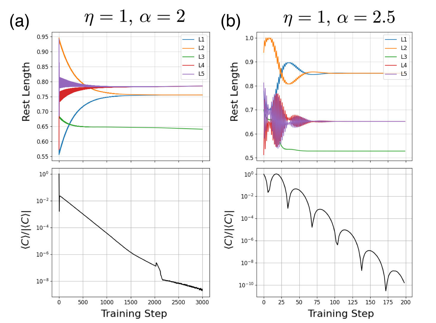
Two simulated trainings of this one-output task are shown in Fig. 5. Both trainings use the full nudge, , and the learning rate is varied. Fig. 5(a) depicts the standard training regime, where . Training takes an excessively long steps to reach the minimum cost, with training times increasing with decreasing learning rate. and exhibit oscillatory dynamics over the course of training, while and incrementally move towards their goal values. Increasing the learning rate to moves us into the “overtraining” regime, Fig. 5(b), in which each learning degree of freedom can evolve past its goal value in a single training step. Here, training time is reduced significantly to only steps, but the cost function does not decrease monotonically over the course of training. The cost can increase by up to an order of magnitude in only a few training steps, but on average decreases by orders of magnitude. The rest lengths also exhibit strong oscillatory behavior, and can even switch their symmetry states between training steps. While this type of overtraining is in principle possible to perform experimentally, the unstable learning dynamics make for a non-ideal demonstration of coupled learning’s capabilities.