0 \vgtccategoryResearch \vgtcpapertypeplease specify
Force Rendering and Its Evaluation of
a Friction-based Walking
Sensation Display for a Seated User
Abstract
Most existing locomotion devices that represent the sensation of walking target a user who is actually performing a walking motion. Here, we attempted to represent the walking sensation, especially a kinesthetic sensation and advancing feeling (the sense of moving forward) while the user remains seated. To represent the walking sensation using a relatively simple device, we focused on the force rendering and its evaluation of the longitudinal friction force applied on the sole during walking. Based on the measurement of the friction force applied on the sole during actual walking, we developed a novel friction force display that can present the friction force without the influence of body weight. Using performance evaluation testing, we found that the proposed method can stably and rapidly display friction force. Also, we developed a virtual reality (VR) walk-through system that is able to present the friction force through the proposed device according to the avatar’s walking motion in a virtual world. By evaluating the realism, we found that the proposed device can represent a more realistic advancing feeling than vibration feedback.
keywords:
Virtual Reality, Locomotion Interface, Seated Position, Walking Sensation, Friction ForceHardwareHaptic devices; \CCScatHuman-centered computingVirtual reality
1 Introduction
Recently, many haptic devices representing realistic dexterous hand manipulation and body movement have been developed. Among these devices, some attempt to represent the sensation of walking to improve immersion in the virtual world. Most of these locomotion devices represent the sensation of walking on a solid ground in an infinite space by canceling the user’s movement while the user is performing the real walking motion in a standing posture [1, 2, 3, 4, 5, 6, 7, 8, 9, 10]. However, these devices tend to be large and require some support instruments. Also, although the real walking motion improves the realism of walking, the motion also causes fatigue. Therefore, to enable users to enjoy virtual walking for a longer time, it is necessary to reduce this fatigue.
Here we attempt to represent the walking sensation while the user remains seated. In the case of a seated walking display, the user would feel less fatigue, and the device does not require additional supports because the real walking motion is not involved. Some previous studies have attempted to represent the walking sensation to a seated user [11, 12, 13, 14]. However, these studies focused only on the representation of leg motion or the pressure and impact applied to the sole of the foot, rather than the sole of the shoe. Few studies have attempted to represent the longitudinal friction force on the sole generated as a reaction force following kicking the ground during walking.
We thought that the friction force applied by kicking the ground is especially important when representing kinesthetic sensation and the advancing feeling (the sense of moving forward) during walking. Therefore, here we attempted to represent the walking sensation by displaying this longitudinal friction force on the sole.

(a) (b)
2 Related works
2.1 Locomotion Devices with Real Walking Motion
Many locomotion devices have been developed that aim at representing the sensation of walking in a virtual world. Many of these devices cancel the user’s movement while the user is performing the real walking motion in a standing posture.
For example, a redirection approach [1, 2, 3] is an attempt to extend a limited walking space to an infinite space by secretly modifying the images displayed in the head-mounted display (HMD) and guiding the user. Nevertheless, guidance with spatially distorted images cannot be used within a small walking space and thus requires a large walking space. Guidance without discomfort has been achieved by modifying the images during blinking [3]. However, this requires a non-narrow walking space.
On the other hand, some studies have attempted to cancel the user’s motion by moving the floor. If the floor is moved in the opposite direction of the user’s movement, the user can walk infinitely in a limited space. For example, using a parallel-link mechanism, Iwata et al. [4] move the plate on which the user’s feet are put. Also, several virtual walking systems [5, 6, 7] use a treadmill mechanism to maintain the user’s position. During real walking, we kick the ground with each step and, as a reaction to the kicking force, a friction force is applied to the sole of the foot. Such a friction force works as a driving force to advance the body forward. However, when using devices that move the floor, the movement of the floor cancels the kicking force, and the user feels weaker friction on the floor. Thus, the advancing feeling produced by these approaches is limited. Meanwhile, the device in [8] attempted to reduce the driving force itself, which is generated by kicking the ground, by reducing the friction between the sole of the shoes and the bowl-shaped walking space; this device needs no actuator and, therefore, the device can be relatively compact. However, these approaches have a common problem in that they cause the feeling of walking with little friction or on a slippery floor.
Another idea is to make the user take steps on the spot [17]. These authors attempted to represent the walking sensation by making the user perform a stepping-like motion. In this method, only the sensor to detect the user’s step is needed, and there is no need to prepare a large apparatus or space. In addition to the stepping-like motion, an arm swing motion can also generate a realistic walking sensation [18]. Kitson et al. compared a motion-cuing locomotion interface with a general joystick [19]. Zanotto et al. have used a vibrotactile feedback on foot using embedded sensors and actuators in the footwear [20]. Another paper [21] compared the walking interaction types and evaluated their naturalness. However, although those types of study use cost-effective devices, the advancing feeling is limited.
When the user is performing the real walking motion or stepping-like motion, and the visibility is obscured by the HMD, there is a danger that users will lose their balance. Thus, to provide a safe virtual walking experience, some support instruments are needed. Also, the real walking motion causes fatigue, making long-time experience difficult, although it cannot be simply regarded as a problem in terms of realism.
2.2 Walking Displays while the User Remains Seated
Some previous studies have attempted to produce a walking sensation to a seated user. A pedal-structured device has been used to represent the walking sensation to a seated user by representing the motion of the leg during walking [11]. Using a mechanism of lifting plates, Ravikrishnan et al. [12] attempted to represent the walking sensation by representing the pressure applied to the sole during walking. In the case of these “seated” walking displays, the user’s body is supported by the chair and, thus, no additional supports are needed. Also, these devices do not cause fatigue. However, these devices need to be driven by a strong actuator due to the weight of the user’s legs.
On the other hand, there are devices that represent the impact applied to the sole when the foot is landed by giving a vibration stimulus [22, 13]. Those studies were able to use a simple device because of a vibration actuator. Terziman et al. added an artificial visual effect named ”King-Kong effects” to enhance the sensation of walking [23]. Another study utilized the footstep motion while sitting as an input to advance the avatar in the virtual world [14]. In that study, the footstep motion is utilized not only as an input but also as a “manual actuator” to present the pressure on its own sole. The device needs no “machine actuator”, thus the compact design is realized.
Although the devices mentioned above represent leg motion, pressure, and impact during walking, there are few studies that represent the friction force applied when kicking the ground. During real walking, when the foot is landed, or the walker kicks the ground, a longitudinal friction force is applied to the sole. This friction force works as the brake and the driving force during walking. Thus, the sensation represented by the previous devices without the friction force is similar to the sensation of footsteps on the spot, which does not represent the haptic feeling of advancing. We assume this friction force is important to represent walking sensations involving the feeling of advancing. The total impulse by forward and backward friction forces is especially important for determining the total advancement. Kato et al. demonstrated a prototype of presenting this friction force [24]. However, the displayed force considers only the timing of hitting and kicking the ground, without considering the impulse by friction forces, and no evaluation was reported.
Here we aimed to represent the sensation of walking by presenting the longitudinal friction force while the user remains seated. When we present the longitudinal friction force, we do not have to directly counter the weight of the leg in the vertical direction. Thus, a simple walking display can be realized. Also, we consider the impulse by friction forces in force rendering and provide a rigorous user study to investigate the effectiveness of the walking sensation display.
3 Measurement Test of Friction Force
3.1 Measurement
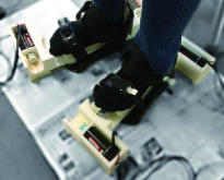
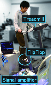
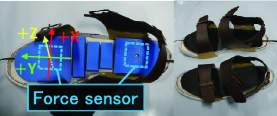
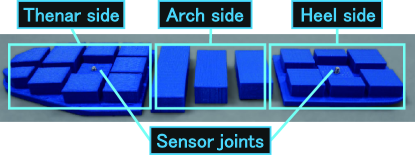
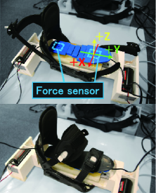
To represent the walking sensation by presenting the friction force, we first need to know the actual friction force applied on the sole of the foot during walking. Ground reaction force, which has been measured classically [15, 16], is the counteracted force against the action forces exerted by the sole of the shoe on the ground. The “pressure” applied on the sole of the foot during walking has been previously examined [25, 26]. However, to our best knowledge, no study has measured the friction force on the sole of the foot during walking. Therefore, we first made measurements of this force. Fig. 2 (a) shows the experimental situation. As in Fig. 2 (b), we used a sandal with flat insoles, and placed two three-axis force sensors (USL06-H5-50N, by Tec Gihan Co., Ltd.); one where the participants put their thenar of the foot and the other where they put their heel. To prevent the user’s weight from concentrating on the force sensor, we placed spacers that cover the sensors (Fig. 3) and flattened the part on which the participants put their foot. We placed the spacer carefully so as not to impair the flexibility of the sandal and placed the rubber sheet (GS-08, by WAKI SANGYO Co., Ltd.) on the spacer to avoid the user’s foot from slipping. The Z-axis’ negative direction of the force sensor corresponds to the direction of gravity, and the Y-axis’ positive direction corresponds to the forward direction of walking. We used a treadmill to measure the friction force when walking at 1.0, 2.5, and 4.0 km/h. 4.0 km/h is the speed that is generally self-selected when walking without any constraints on a flat surface, and is also used in the study of displaying footstep sounds [27]. Other speeds (i.e. 1.0 km/h and 2.5 km/h) were chosen as we determined the number of speed conditions was three due to the limited experimental period, and the constant speed difference between conditions was set to 1.5 km/h. The treadmill permanently moves the belt of the walking space backward. Thus, the forward friction force will be measured as smaller than the force when walking over the ground, and the backward friction force will be measured as larger. However, there is a correlation between the force on a treadmill and the force during walking over the ground [28]. Thus, we prioritized the alignment of walking speed. We explain the correction method of this error in section 4.3.
(a) (b)
Four participants (average age years) joined this measurement. They each walked 30 steps (each foot landed 15 times) for each walking speed, and we extracted the middle ten steps (from the 4th step to the 13th step) for the analysis because we focus on the steady walking of the central part of the walk. To get used to walking with a sandal on the treadmill, the participants practiced for about 10 s before the measurement of each speed. The participants also took a 30 s break between the measurement of each speed.
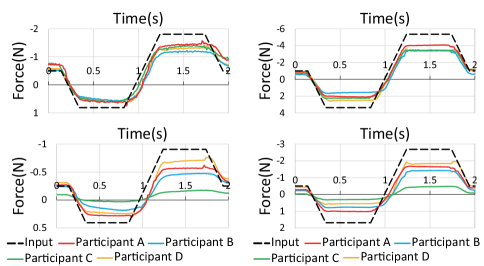
Fig. 4 shows the measured friction force of each walking speed. In these graphs, we show the averaged waves of ten steps in the Y-axis direction. As described below, extremely strong load was applied on the thenar side at the end of each step. Thus, the scale of the values stronger than 2 N in the thenar side graphs was set differently. The actual force applied on the sole corresponds to the reaction force of the measured force by the sensors. Thus, the friction forces applied on the sole were obtained by reversing the sign of the forces in Fig. 4. In other words, the positive values in this figure show the backward friction forces, and the negative values in this figure show the forward friction forces.
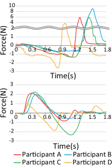
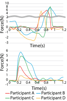
(1.0 km/h) (2.5 km/h)
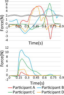
(4.0 km/h)
3.2 Discussion
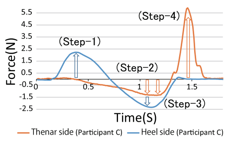
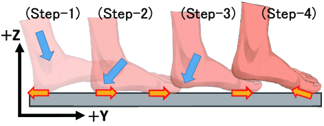
As a result of the measurement test, we could confirm the regularity in the transition of the friction force during walking. As a representative example, in Fig. 5, we show the values at 1.0 km/h of a certain participant. Fig. 6 shows the outline of the applied friction force inferred from the measurement.
At the beginning of the first step, (Step-1), a backward force is applied on the heel side, and then (Step-2) forward force is applied on both the heel side and thenar side. Then (Step-3), the forward force on the heel side becomes small. Finally (Step-4), a large backward force is suddenly applied on the thenar side. The friction force in (Step-1) is inferred as the reaction force against the force used to put the foot forward. This force is inferred to act as a brake of the body and to stabilize the walking motion. The friction forces in (Step-2) and (Step-3) are inferred as the reaction force against the backward force applied when kicking the ground. This reaction force acts as a driving force to move the body forward. As the weight shifts from the heel side to the thenar side, the heel is lifted. Thus, in (Step-3), the force is applied only on the thenar side. As the angle between the foot and the plate changes, the weight of the body is applied not only in a vertical direction (Z-axis) but also in a horizontal direction (Y-axis). This is considered as the cause of the sudden change in force (Step-4). Thus, the force is applied by the longitudinal friction force only in (Step-1), (Step-2), and (Step-3). When we increased the speed of the treadmill during the measurement, the forward force applied on both the heel and thenar sides like (Step-2) does not appear because of a reduction in the time from when the heel side is grounded to the foot leaving the ground. Except for (Step-2), similarly shaped forces were applied regardless of the speeds and participants.
4 Development of a Friction-based Walking Sensation Display for a Seated User
4.1 Hardware Design
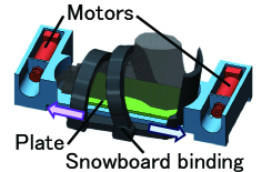
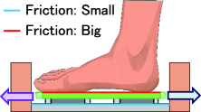
Because we detected regularity in the transition of the friction force during walking, we attempted to represent the walking sensation by mimicking the measured friction force. Specifically, we attempted to represent the friction force in (Step-1), (Step-2), and (Step-3), as described in the previous section. We do not represent the friction force in (Step-4) because we believe this force is caused by body weight load. The reaction force to support the body weight itself will be important for representing the walking sensation. However, in our method, we do not present the upward force. Thus, if we present the reaction force to the body weight only when the foot leaves ground, this would likely confuse the user. As mentioned above, the transitions of the friction force differ between the thenar side and the heel side. However, to simplify the device and attempt to represent the walking sensation using the 1-DOF simple friction force display, in this study, we regarded the entire sole as the one presentation area of the friction force. We first present the friction force forward and then backward. We developed a haptic device to realize the 1-DOF friction force. Fig. 7 (a) shows the entire outline of the proposed device. As shown in Fig. 7 (b), the user’s foot is placed on a plate on a linear rail (SRS9XN, by THK Co. Ltd). By winding the wire (HARDCORE X8 #6.0, by DUEL CO. Inc) attached to the plate with a motor (RE40 148877, by Maxon Motor AG), a friction force is applied to the sole. The friction between the linear rail and the movable part is extremely small (dynamic friction coefficient , which is much smaller than the coefficient of the friction that works between typical ice and iron, 0.027). Thus, this device can present the friction force without the influence of the leg’s weight, and (because the resistance force is small) this can be done rapidly. We controlled the motors using a microcomputer (Arduino Uno, by Arduino S.R.L.). By sending the signal from the microcomputer to the motor driver (MD10C, by Cytron Technologies) connected to the 10 V power supply, a voltage between 0 and 10 V is applied to the motors. To fix the user’s leg to the frame, we used a snowboard binding (ZUMA BLACK S/M ZUMA board binding, Swallow Ski Co. Ltd).
(a) (b)
4.2 Performance Test
4.2.1 Experimental Setup
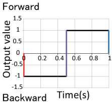
To investigate the friction force that the proposed display can present, as well as the responsiveness of the device, we measured the friction force generated by the device using the same sensor described in Section 3. Fig. 8 shows the experimental situation and the placement of the force sensors. As in Section 3, we placed the sensors on the thenar side and the heel side and covered them with a rubber sheet. Because we planned to represent the walking sensation by presenting of friction force in the order of “backward” then “forward”, we measured the friction force by applying the load in this order. Fig. 9 shows the transition of the output signal in this measurement. The positive value shows the signal to the motor towing the plate forward (forward motor) while the negative value shows the signal to the motor towing backward (backward motor). At first, we increased the output value to the backward motor linearly to reach the maximum value in 0.2 s. Next, after maintaining the maximum value for 0.5 s, we decrease the value linearly to zero in 0.2 s. After this procedure, we input the same signal to the forward motor.
The rise and the fall times (0.2 s) were determined to ensure the output stabilities. Also, the presentation time of the maximum load (0.5 s) was determined to ensure that we could collect sufficient data. We controlled the load of the motors by the PWM (Pulse Width Modulation) signals from the microcomputer (Arduino Uno) and used the three PWM outputs of the Arduino Uno (95, 175, and 255) as the maximum output signals (corresponding to the output value 1.0 in Fig. 9). These PWM signals approximately correspond to the duty rates (0.37, 0.69, and 1, respectively). When the duty rate is 1, 10 V is continuously applied to the motor. The minimum signal (95) was determined to ensure that the proposed device can move the skin of the sole, regardless of the participant. The medium signal (175) was the average value of the minimum (95) and maximum (255) values. The same four participants of Section 3 joined here. We measured the friction force ten times for each signal pattern (10 times 3 signal patterns 30 trials).
(a) (b)

4.2.2 Results and Discussion
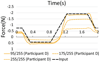
Fig. 10 shows the averaged result of each signal pattern. We show the averaged point of ten measurements. As representative examples, we show the results when the maximum signals are 95 and 255. From this figure, we found that although the variance of the friction force on the thenar side was small, the friction force on the heel side varied depending on the participant. Because of the structure of the proposed display, there were some differences in the fixation of the foot depending on the participant. The structure around the heel and ankle is surrounded by the front and back fixtures (Fig. 7 (b)). Thus the fixation was influenced by the shape of the foot. On the other hand, the thenar side is fixed only by the single belt. We believe that this made the influence of the foot’s shape small, and also reduced the variance of the friction forces.
(95/255) (255/255)
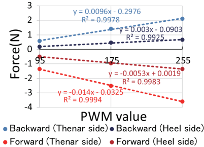
Fig. 11 shows the proportional relation between the backward/forward friction forces and the output signals. We calculated this relation based on the averaged peak loads of all participants. In this figure, we show the PWM signal value while its divided value by 255 corresponds to the duty rate. We found that the magnitudes of the forces applied to the thenar side and the heel side are linearly proportional to the duty rate. In fact, as shown in Fig. 11, all of the coefficients of determination were greater than 0.99. On the other hand, there was one participant for whom the measured backward friction force on the heel side did not change significantly, even if the duty rate was changed (Fig. 12). Due to the structure of the device, the heel side sometimes rises a little off the ground when the plate moves backward, and the foot is pressed against the fixture. This might have caused instability for the force on the heel side. Considering this problem, as well as the problem of the variance (as mentioned above), we feel that it is necessary to improve the structure of the device near the heel side. However, the floating distance was small, and it did not greatly disturb the friction force. Also, although the variation range was small, we could present a friction force proportional to the duty rate, even for the participant whose heel side lifted off the ground. Thus, we found that the proposed device can present the friction force proportional to the output signal.
Also, in order not to generate the unnecessary load when the output signal is 0, the proposed display adjusted the position of the friction display plate only when it greatly deviated from the center. At the time of the preliminary experiment, we found that the plate can return to the center position automatically by the elasticity of the skin. Thus, we decided not to apply the extra force during the transition to the no-load state. As a result, at the moment the proposed display transitioned to the no-load state, the position of the plate did not return to the neutral position perfectly. This is the reason that the friction force at the no-load state was not 0. On the other hand, there were no situations where the plate is gradually shifting in some directions. Thus, we believe that the proposed display can present the friction forces in succession.
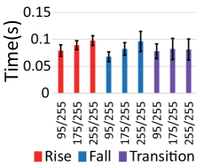
Next, to investigate the responsiveness of the proposed display, we measured the friction force when the rise and fall times of the output signals are 0 s. As shown in Fig. 13 (a), we gave the signal that rapidly changes in 0 s, and measured the friction force for the three maximum signals (PWM signal 95, 175, and 255). Fig. 13 (b) shows not only the rise and the fall times of the measured friction force but also the transition time from the end of the backward output to the forward peak load. The time until the value drops for the first time after the output was defined as the rise time.
(a) (b)
As shown in Fig. 13(b), we found that the proposed display responds within about 0.1 s, regardless of the magnitude or direction of the friction force. Also, we confirmed that the responsiveness did not deteriorate when the display subsequently moved the plate in the opposite direction. Thus, the proposed device can rapidly and stably present a friction force.
4.3 Calculation of Output Signal
From previous measurements, we estimated the friction forces during walking and the friction forces per duty rate presented by the proposed display. From these data, to represent the walking sensation, we calculated the output signal to the proposed display.
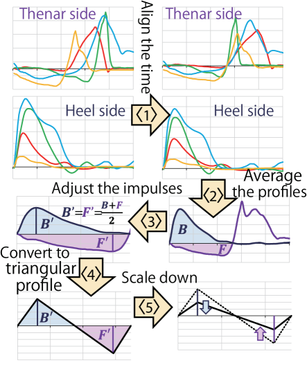
Fig. 14 shows the outline of the procedure used to calculate the output signal from the friction force measured during walking at 2.5 km/h. Below, we introduce the specific steps of the procedure.
-
Align the time of the friction force profile [the time during (Step-1), (Step-2), and (Step3)] of each participant to the average time of all participants.
-
Average the profiles of all participants per walking speed.
-
Adjust the impulse by the backward friction force () and the impulse by the forward friction force ().
-
Convert to the triangular profile according to the modified impulses () and (), as well as the peak timing of the average profile.
-
Scale down the triangular profile so that it can be presented by the proposed display.
First, to average profiles of each participant’s friction forces applied during walking, we calculated the average time from (Step-1) to (Step-3) and aligned these to the average time . Next, we averaged the profiles of each walking speed .
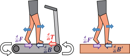
There is one problem: the friction force profiles during walking were measured on a treadmill, and these profiles will be different from the profiles during walking over ground. Thus, backward friction force was measured larger than expected and the forward friction force was measured smaller than expected because the treadmill makes the floor belt move backward. Thus, some adjustments were necessary. As shown in Fig. 15, we named the impulses of the backward friction force and the forward friction force measured on the treadmill as and respectively. Also, we named the impulses by the treadmill as . Also, we named the impulses of the backward friction force and the forward friction force during walking over the ground as and , respectively. These impulses correspond to the impulses we aim to represent using the proposed device. We defined the impulses as the area surrounded by the friction force profiles (Fig. 14). Under this determination, if we suppose that the equations and hold, the equation also holds. Also, if we suppose that the body movement during walking at low speed stops step-by-step, it is considered that the brake impulse cancels the driving impulse . Assuming that the equation holds, the equation also holds. Thus, we scaled the entire friction force profiles to convert the surrounded areas to .
Although the proposed display can rapidly present the friction force, the presented friction force becomes a little duller than the output signal. Thus, it is difficult to present the same force profile measured during walking. Also, although the measured friction force differed for each part of the sole, the proposed display applies the friction force over the entire sole. Thus, we have to convert the force profiles calculated above to those that the proposed display can present. We selected the triangular profile as the output signal because it can be stably presented by the proposed device. First, we output the triangular profile corresponding to the backward impulse, followed by the forward impulse. The triangular profile reaches the top vertex at the same time as the peak timing of the averaged profile. We regarded the timing of (Step-1) and (Step-3) as the peak timing. As mentioned above, when the walking speed increased, the state (Step-2) in which the forward friction forces are applied to both the thenar and heel sides simultaneously disappears. Thus, we did not take the timing of (Step-2) into consideration, because we could not interpolate the timing between each walking speed based on (Step-2). The heights of each triangle were calculated so that their areas correspond to the impulses, as mentioned above .
By this approach, we could obtain the target profiles of the friction force. However, the current version of the proposed display cannot present as large a friction force as the target profile. Thus, we calculated a scaling rate that scales down the maximum friction force of the target profiles to the maximum friction force that the proposed display can present, and scaled down all the target profiles by this reduction rate . Thus, we obtained the triangular friction force profile per walking speed and interpolated the peak timing and the peak friction force between the walking speeds. Finally, we calculated the actual output signal based on the relationship between the output signal to the proposed display and the friction force that the proposed display presents. To use the value at the time of stable output as the standard value, we calculated this relationship based on the measurement result when the rise and fall times of the output signal were set to 0.2 s, where we increased and decreased the output value linearly to reach the maximum and minimum value in 0.2 s, respectively, with 0.5 s interval.
5 Representation of Walking Sensation
In this section, we investigated whether the proposed display can realistically represent the walking sensation.
5.1 Walking Experience System
To represent the walking sensation, we developed a system in which the output signal is sent to the proposed display according to an avatar’s walking motion and speed in a virtual world. In this system, the graphical images displayed in the HMD are rendered according to the movement of the avatar’s head position.
In the virtual world, the avatar’s movement is controlled using a game pad (Rumblepad 2, by Logicool Co., Ltd.). This system displays the view from a camera placed at the avatar’s head position onto the HMD (Oculus Rift DK2, by Oculus VR, Inc.). We developed this system based on a game engine (Unity, by Unity Technologies Inc.) and used the character (Ethan) involved in the standard assets of Unity as the avatar. Ethan has a walking animation that was captured using a motion capture system. In our system, we utilized this default animation to display the motion of the legs during walking. In the measurement test, the friction force began to work at the moment the Y-axis’ force is confirmed. Thus, we presented the friction force according to the avatar’s walking speed when Ethan’s foot grounded. To realize the natural walking sensation, we played the sound of footsteps binaurally using the Unity plugin (3DCeption, by Two Big Ears Ltd.), corresponding to when the avatar’s feet were grounded. The sound was played with noise-canceling headphones (QuietComfort 15, by Bose Corporation) to reduce the effects of the environmental noise , as well as the noise from the motor. The output signal was calculated at a rate of 1000 times per second.
5.2 Evaluation of realism
5.2.1 Experimental Setup
We evaluated the realism of the walking sensation represented by the proposed display. We compared our friction force stimuli with both vibration and none stimuli. Twelve participants (average age years), including the four participants who partook in the friction force measurements, joined this experiment. Before the experiment, we briefly explained the concept of our device and system. Using a questionnaire, the participants evaluated the realism of various sensations related to walking while controlling the avatar and walking in a virtual space. For the magnitude estimation, we instructed the participants to walk before taking part in this experiment. The realism of each sensation in the virtual world was scored from 0 to 100 points without a visual analog scale relative to real walking (regarded as 100 points). Based on [11], we selected the sensations listed in Table 1 as the evaluation items while referring to the experiment in the paper, in which the realism of the walking sensation while the user remaining seated was evaluated like our experiment. These items were presented to the participants in both Japanese and English.
| Name | Explanation |
|---|---|
| Driving force | Sensation of the applied driving force to move the body forward |
| Periodicity | Sensation of the repetitiveness of the footstep sensation |
| Muscle tension | Sensation of the muscle tension during walking |
| Kinesthetic sensation | Sensation of the movement of the leg when walking |
| Brake | Sensation of the applied brake force when the foot grounded |
| Advancement | Sensation of the body advancing forward |
| Contact | Sensation of the skin when the foot grounded |
| Balance control | Sensation of balancing body posture during walking |
| Hardness | Sensation of the hardness of the ground when the foot is landed |
| Texture | Sensation of the texture of the ground when the foot is landed |
| Timing | Timing in feeling the footstep sensation |
| Total | Reality of the total system |

The participants evaluated the realism of the walking sensation not only using the proposed display (Friction condition) and without stimulus (None condition). Also, the participants evaluated the realism of a vibration stimulus (Vibration condition) that can be presented using a smaller device than the proposed display. We used 12 V vibrators (a13081500ux0075, by UXCell) to present the vibration stimuli and, to transmit the vibration to the sole, we attached the vibrator embedded plate to the snowboard binding. Vibrator-embedded plates were attached on both the thenar and heel sides. We used the snowboard binding (JOBG-340 S/M, by ACTIVE Co., Ltd.) because the binding used for the proposed display was already unavailable. Fig. 16 shows the device to present the vibration stimuli (tentatively called VibStep).
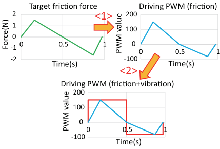
As the output signal to VibStep, we used a rectangular signal that covers the triangular PWM signal used for the proposed device. At the preparation stage of this experiment, we found that if we do not maintain an output signal to the vibrator, the user is unable to perceive the stimulus. If we give the triangular output signal to VibStep, the vibration stimulus is insufficient because the peak load of the triangular signal is fleeting. Thus, we decided to give a rectangular signal to VibStep. Fig. 17 shows the example of the specific procedure used to calculate the output signal to VibStep. After we converted the target friction force profile to the triangular PWM signal to the proposed device , we calculated the rectangular PWM signal that covers the triangular signal . Unlike the proposed display, the stimulus display part of VibStep is divided into the thenar and heel sides. When the output signal is positive, we output it to the vibrator on the heel side; when the output signal is negative, we output it to the vibrator on the thenar side. This type of vibration output presenting on the thenar side following the presentation on the heel side was also adopted in a previous study [13].
(a) (b)
At the beginning of this experiment, the participants evaluated the realism on the ’None’ condition. Next, they evaluated the realism on the ’Friction’ condition or the ’Vibration’ condition. Finally, they evaluated the realism on another condition which they did not evaluated in the second evaluation. In the second evaluation, half of the participants evaluated on the ’Friction’ condition, and the other half of the participants evaluated on the ’Vibration’ condition. In our system, the presented friction force and the graphical images are changed according to the avatar’s walking speed. However, in this experiment, we limited the walking speed to 1.0, 2.5, and 4.0 km/h (at which we measured the friction force during actually walking). For each stimulus condition (None, Vibration, and Friction), half of the participants evaluated the realism in the order of 1.0, 2.5, and 4.0 km/h, and the other half evaluated the realism in the order of 4.0, 2.5, and 1.0 km/h.
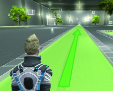
The participants evaluated the realism of each condition by controlling the avatar using a gamepad. In this experiment, we limited the avatar’s movement to a simple forward movement. When the participants tilted the joystick to a certain extent, the avatar started walking at the specified speed. Fig. 18 shows the experimental set up of the virtual space. To make it easy to sense the distance, we used a scene in which some objects are placed.

5.2.2 Results
We conducted Friedman test for speed and stimuli conditions with repeated measures, which does not assume normality of the samples’ distribution. We also conducted multiple comparisons by the post hoc test using Wilcoxon rank sum test with Bonferroni’s correction to the items that we could not confirm a main effect of speed in Friedman analysis and ignore the speed difference of the samples. There were a large variance between participants. Also, for each item, the maximum and minimum points of each participant were the same only when both points were 0. Thus, as shown below, we normalized the points of each participant before averaging the points of all participants.
-
1.
For each participant, we calculated the maximum point and the minimum point of all data (three stimuli three speeds) belonging to the evaluation item
-
2.
For each participant, we normalized each data belonging to the evaluation item using the equation from 0 to 1
-
3.
When and are at the same point,
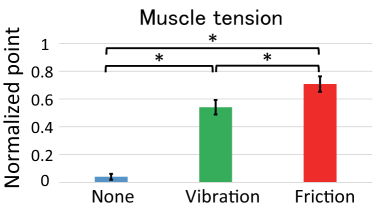
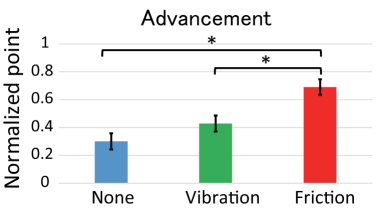
Fig. 19 shows the averaged normalized points of those items for which we found that the ’Friction’ condition was significantly more real than the ’Vibration’ condition (p0.05). The ’Vibration’ and the ’None’ conditions outscored the ’Friction’ condition for no items.
5.2.3 Discussion
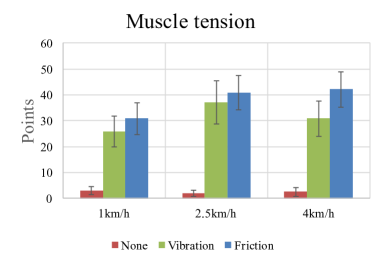
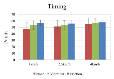
From these findings, we were able to confirm that “muscle tension”, “kinesthetic sensation”, and “advancement” felt more real using the proposed display than when using a vibration stimulus. We believe that the stimulus presented by the proposed display generated not only the sensation on the sole of the foot but also the illusion of the entire leg’s motion. This is based on the detection of significant differences for the two items (“muscle tension” and “kinesthetic sensation”), which are related to the entire leg. Also, the improvement in the “advancement” sensation was greater than for other items. This indicates that the representation of the friction force when kicking the ground generates a strong advancing feeling. Fig. 20 shows the representative raw points before normalization.
However, we detected no significant difference in the realism of the friction force when kicking the ground (the item of “driving force”). In the current version of the proposed display, we presented the friction force on the entire sole by the 1-DOF mechanism. Thus, unlike the vibration stimulus of VibStep, the proposed display cannot represent the shift in the load position from the heel side to the thenar side during walking, which might limit its realism. If we increase the degrees of freedom of the proposed display and represent the weight shift, the realism would likely be improved.
Example comments from the participants are “Fixing the ankle reduces the advancement a bit“ and “I really felt the walking sensation when the friction force was displayed at the fastest speed“ while another participant reported “The presented friction force at the fastest speed was too strong“. Also, one participant reported a little fatigue due to the VR sickness. We should mention the lack of proper counterbalancing in the order of stimuli conditions. We always displayed the ’None’ condition first. Thus, our results might include an effect caused by adding haptic feedback, rather than removing haptic feedback. However, the influence of the order effect would be limited, and would not reverse the differences between the ’None’ and ’Friction’ conditions (Fig. 19).
6 Conclusion
In this paper we describe the development of a novel haptic device to represent the walking sensation with a minimal mechanism and without fatigue. The proposed display represents the reaction force generated when the user’s foot is landed and when kicking the ground by representing the longitudinal friction force applied on the sole during walking. From the measurement test, although there were individual differences in the presented force, we were able to control the friction force. Also, we found that the proposed display could present rapid stimuli within about 0.1 s.
Based on the measured friction force applied on the sole during real walking, we presented the friction force according to the avatar’s walking motion in a virtual world. As a result, we succeeded in achieving a significantly more real advancing feeling and kinesthetic sensation than the vibration stimuli. However, we detected no significant improvement in the realism of some sensations related to walking. When we calculated the output signal to HapStep, we simplified and scaled down the targeted friction force due to the limited performance of our device. If a device is developed that can present larger friction forces more accurately, more realistic walking sensation might be realized. On the other hand, as mentioned above, some users expressed that “the presented friction force was too strong”. The integration of the proposed device with the vibrotactile one, which can modulate stimuli widely, would be good choice to enhance the ’texture’ and ’timing’ representation. If we attempt to represent a compliant ground rather than solid ground, we should represent the effects caused by the deformation of a shoe sole, e.g. stretching force applied on the foot. In our measurements during walking, we cannot truly isolate the gravitational force from the longitudinal friction force. Thus, it is possible that the load measured friction force was larger than the actual load. Therefore, the measurement method will need to be improved as a part of future studies.
The current version of the proposed display tries to represent only the friction force applied when the foot is landed, and the walker kicks the ground. However, there is a possibility that the proposed display can represent other moving sensations, such as jumping or sliding on ice. If we can represent these additional moving sensations, it will become possible to achieve a richer virtual experience.
References
- [1] E. A. Suma, S. Clark, D. Krum, S. Finkelstein, M. Bolas, and Z. Warte. Leveraging Change Blindness for redirection in Virtual Environments. Proc. of IEEE Virtual Reality, pp. 159–166, 2011.
- [2] C. T. Neth, J. L. Souman, D. Engel, U. Kloos, H. H. Buelthoff, and B. J. Mohler. Velocity-Dependent Dynamic Curvature Gain for redirected Walking. Proc. of IEEE Virtual Reality, pp. 151–158, 2011.
- [3] E. Langbehn, G. Bruder, and F. Steinicke. Subliminal Reorientation and Repositioning in Virtual Reality During Eye Blinks. Proc. of ACM Symposium on Spatial User Interaction 2016, p. 213, 2016.
- [4] H. Iwata, H. Yano, and F. Nakaizumi. Gait Master: A Versatile Locomotion Interface for Uneven Virtual Terrain. Proc. of IEEE Virtual Reality, pp. 131–137, 2001.
- [5] H. Iwata. Walking about Virtual Environments on an Infinite Floor. Proc. of IEEE Virtual Reality, pp. 286–293, 1999.
- [6] A. De Luca, R. Mattone, and P. Robuffo Giordano. Feedback / Feedforward Schemes for Motion Control of the CyberCarpet. Proc. of IEEE International Conference on Robotics and Automation, pp. 3532–3537, 2006.
- [7] A. Vijayakar and J. Hollerbach. Effect of Turning Strategy on Maneuvering Ability using the Treadport Locomotion Interface. Presence: Teleoperators and Virtual Environments, Vol. 11, No. 3, pp. 247–258, 2002.
- [8] http://www.virtuix.com/ (Last access: Jan. 28, 2017)
- [9] F. Fontana, and Y. Visell. Walking with the Senses. Logos Verlag, 2012.
- [10] F. Steinicke, Y. Visell, J. Campos, and A. Lécuyer. Human Walking in Virtual Environments - Perception, Technology, and Applications. Springer, 2013.
- [11] Y. Ikei, S. Kato, K. Komase, S. Imao, S. Sakurai, T. Amemiya, M. Kitazaki, and K. Hirota. Vestibulohaptic Passive Stimulation for a Walking Sensation. Proc. of IEEE Virtual Reality, pp. 185–186, 2016.
- [12] R. P. Jayakumar, S. K. Mishra, J. F. Dannenhoffer, and A. M. Okamura, Haptic Footstep Display. Proc. of IEEE Haptics Symposium, pp. 425–430, 2012.
- [13] T. Hamada, K. Yoshiho, R. Kondo, Y. Ikei, K. Hirota, T. Amemiya, and M. Kitazaki. Changing Perceived Leg Length and Motion on Virtual Walking Generator. Proc. of the 23rd International Display Workshops, 2016.
- [14] T. Ohshima, R. Shibata, H. Edamoto, and N. Tatewaki. Virtual ISU: Locomotion Interface for Immersive VR Gaming in Seating Position. Proc. of SIGGRAPH ASIA 2016 Poster, Article 18, No. 2, 2016.
- [15] J. Nilsson and A. Thorstensson. Ground Reaction Forces at Different Speeds of Human Walking and Running. Acta Physiologica Scandinavica, Vol. 136, No. 2, pp. 217–227, 1989.
- [16] K. Moriyasu and T. Nishiwaki. The Influence of Gait Velocity on 3 Dimensional Reaction Force in Contact Area. Proc. of the Symposium on Sports Engineering, pp. 277–280, 2009.
- [17] M. Slater, A. Steed, and M. Usoh. The Virtual Treadmill: A Naturalistic Metaphor for Navigation in Immersive Virtual Environments. Proc. of Eurographics, pp. 135–148, 1995.
- [18] N. C. Nilsson, S. Serafin, and R. Nordahl. The Perceived Naturalness of Virtual Locomotion Methods Devoid of Explicit Leg Movements. Proc. of Motion on Games, pp. 155–164, 2013.
- [19] A. Kitson, A. M. Hashemian, E. R. Stepanova, E. Kruijff, and B. E. Riecke. Comparing Leaning-based Motion Cueing Interfaces for Virtual Reality Locomotion. Proc. of IEEE Symposium on 3D User Interfaces, pp. 73–82, 2017.
- [20] D. Zanotto, L. Turchet, E. M. Boggs and S. K. Agrawal. SoleSound: Towards a Novel Portable System for Audio-Tactile Ecological Underfoot Feedback. Proc. of 5th IEEE International Conference on Biomedical Robotics and Biomechatronics, pp. 193–198, 2014.
- [21] R. Nordahl, S. Serafin, L. Turchet, N. C. Nilsson. A Multimodal Architecture for Simulating Natural Interactive Walking in Virtual Environments. PsychNology, Vol. 9, No. 3, pp. 245–268, 2011.
- [22] L. Turchet, P. Burelli, and S. Serafin. Haptic Feedback for Enhancing Realism of Walking Simulations. IEEE Transactions on Haptics, Vol. 6, No. 1, pp. 35–45, 2013.
- [23] L. Terziman, M. Marchal, F. Multon, B. Arnaldi, and A. Lecuyer. The King-Kong Effects: Improving Sensation of Walking in VR with Visual and Tactile Vibrations at Each Step. Proc. of IEEE Symposium on 3D User Interfaces, pp. 19–26, 2016.
- [24] G. Kato, Y. Kuroda, K. Kiyokawa, and H. Takemura. HapStep: A Novel Method to Sense Footsteps While Remaining Seated Using Longitudinal Friction on the Sole of the Foot. Demonstration in AsiaHaptics, pp. 105–111, 2016.
- [25] G. L. Warren, R. M. Maher, and E. J. Higbie. Temporal Patterns of Plantar Pressures and Lower-leg Muscle Activity during Walking: Effect of Speed. Gait Posture, Vol. 19, No. 1, pp. 91–100, 2004.
- [26] F. W. Galbraith and M. V. Barton. Ground Loading from Footsteps. The Journal of the Acoustical Society of America, Vol. 48, No. 5B, pp. 1288-1292, 1970.
- [27] L. Turchet, I. Camponogara, F. Nardello, P. Zamparo, and P. Cesari. Interactive Footsteps Sounds Modulate the Sense of Effort without Affecting the Kinematics and Metabolic Parameters during Treadmill-walking. Applied Acoustics, Vol. 129, pp. 379–385, 2018.
- [28] M. Okada, E. Saito, K. Ohtsuka, H. Sakurai, S. Takeda, T. Teranishi, Y. Suzuki, T. Okanishi, K. Terao, J. Kaga, and Y. Kanda. Comparison of Ground Reaction Forces between Overground and Treadmill Walking. The Journal of Japanese Physical Therapy Association, Vol. 29, No. 6, pp. 209–217, 2002.