Magnomechanically controlled Goos-Hänchen shift in cavity QED
Abstract
Phenomena involving interactions among magnons, phonons, and photons in cavity magnomechanical systems have attracted considerable attention recently, owing to their potential applications in the microwave frequency range. One such important effect is the response of a probe field to such tripartite interaction between photon-magnon-phonon. In this paper, we study Goos-Hänchen shift (GHS) of a reflected probe field in a cavity magnomechanical system. We consider a YIG sphere positioned within a microwave cavity. A microwave control field directly drives the magnon mode in YIG sphere, whereas the cavity is driven via a weak probe field. Our results show that the GHS can be coherently controlled through magnon-phonon coupling via the control field. For instance, GHS can be tuned from positive to negative by tuning the magnon-phonon coupling. Similarly, the effective cavity detuning is another important controlling parameter for GHS. Furthermore, we observe that the enhancement of GHS occurs when magnon-phonon coupling is weak at resonance, and when the magnon-photon coupling is approximately equal to the loss of microwave photons. Our findings may have potential significance in applications related to microwave switching and sensing.
I introduction
The cavity magnomechanical system consisting of magnons in a single-crystal yttrium iron garnet (YIG) sphere strongly coupled to the cavity mode has been theoretically proposed and experimentally demonstrated [1]. Such a system has emerged as an important frontier in the realm of cavity electrodynamics (QED), drawing substantial attention in recent times [2, 3, 4, 5, 6, 7]. It offers a unique platform for exploring interactions among photon, magnon, and phonon modes. Such interactions led to some interesting outcome such as generation of entanglement [8, 9], preparation of squeezed states [10, 11], coherent superposition and bell states [12].
Meanwhile, studies on the response of microwave field to the system arising from the coupling of the magnon, phonon, and the cavity microwave photon, reveal the magnon-induced absorption, as well as the magnomechanically induced transparency [13, 14, 15, 16, 17, 18, 19, 20]. These phenomena originate from the internal constructive and destructive interference that can be interpreted by analogy with the optomechanical induced absorption and transparency, respectively, in the cavity optomechanics [21, 22, 23]. Tunable slow and fast light has also been demonstrated in the cavity magnomechanics [14, 15, 16, 17]. In this paper, we focus on another crucial aspect of optical response in a cavity magnomechanical system, known as the Goos-Hänchen shift (GHS).
In classical optics, the Goos-Hänchen shift occurs when a classical electromagnetic light beam reflects from the interface of two optically different media. It is actually a lateral shift of reflected light beam from the actual point of reflection at the interface and first reported in an experiment by Goos and Hänchen [24, 25]. The GHS has magnificent applications in optical switching [26], optical sensors [27, 28], beam splitters [26], optical temperature sensing [29], acoustics [30], seismology [31], and regarding the theory of waveguides [32]. The GHS can be positive or negative depending on the properties of the system under consideration. So far various quantum systems have been investigated for the manipulation of GHS, such as atom-cavity QED [33, 34, 35], quantum dots [36, 37], cavity optomechanics [38, 39, 40], two-dimensional quantum materials [41, 42, 43], and a spin-polarized neutron reflecting from a film of magnetized material [44]. However, to the best of our knowledge, manipulation of GHS in a cavity magnomechanical system has not been reported yet that could have possible potential applications in sensing and switching.
In this paper, we investigate the manipulation of GHS in the reflected portion of the incident probe field in a cavity magnomechanical system using stationary phase method. We show that the magnon-phonon coupling strength, controlled via an external microwave driving field, flexibly alters the GHS from negative to positive. The negative GHS becomes larger at weak magnon-phonon interaction strength. We also show that GHS can be controlled by tuning the effective cavity detuning. By varying the effective detuning at zero magnon-phonon coupling strength, GHS can be effectively tuned from positive to negative. Finally, we explore the effects in both weak and strong coupling limits, determined by the ratio of magnon-photon coupling to the lifetime of microwave photons. We find that the optimum value to achieve enhanced GHS corresponds to magnon-photon coupling of approximately the same strength as the cavity decay rate.
The rest of the paper is organized as follows: In section II, we explained the physical system. Section III deals with results and discussion. Finally, we conclude in section IV.
II system model and Hamiltonian
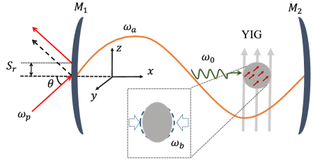
We consider a cavity-magnomechanical system that consists of a single-mode cavity of frequency with a YIG sphere placed inside the cavity as shown in Fig. 1. Both nonmagnetic mirrors and are kept fixed, assuming is perfectly reflecting while is partially reflecting. The left mirror has a thickness and permittivity . The effective cavity length is and effective cavity permittivity in the presence of a YIG sphere is . In Fig. 1, a uniform bias magnetic field along the -direction is applied on the YIG sphere, which excites the magnon modes of frequency . These magnon modes are coupled with the cavity field through magnetic dipole interaction. The excitation of the magnon modes inside the sphere varies the magnetization, resulting in deformation of its lattice structure. This magnetostrictive force causes vibrations of the YIG sphere with phonon frequency , which establishes magnon-phonon interaction.
Usually, single-magnon magnomechanical coupling strength is very weak [45]. However, we consider that the magnon mode of the YIG sphere is directly driven by a strong external microwave source having frequency and amplitude . Here, is the gyromagnetic ratio, is the total number of spin inside the YIG sphere, and is the magnitude of external drive field along -direction. This microwave drive plays the role of a control field in our model and enhances the magnomechanical (magnon-phonon) interaction of the YIG sphere. Additionally, the cavity is probed by a weak field with frequency , incident from vacuum at an angle along the -axis. The amplitude of the probe field is . Here, is the power of the probe field, and is the cavity decay rate. The probe light is reflected back from the surface of mirror with some lateral displacement along the -axis known as GHS and denoted by .
 |
In order to investigate GHS, we employ stationary phase theory in which well-collimated probe field with sufficiently large linewidth can be consider as plane wave. Under the stationary phase condition, the GHS in the reflected probe laser beam is given by [46, 47]:
| (1) |
where, is the wavelength of incident probe field, is the phase of the TE polarized reflection coefficient , and . Eq. (1) can be expressed in a more explicit form:
| (2) |
The reflection coefficient used in the above equation can be drived using standard transfer matrix theory [35]:
| (3) |
where and are the element of total transfer matrix:
| (4) |
Here, the element relates the input and output of the electric field associated with probe field propagating through the cavity and is given by:
| (5) |
where is the -component of the wave number of probe field. Here, is the speed of light and represents the susceptibility of the layer of the medium. The effective permittivity of the cavity is determined by the non-linear susceptibility as . The susceptibility depends on the non-linear interaction between the cavity field, magnon, and phonons in the presence of the microwave drive. As a result, the resonance conditions for the probe field are modified, resulting in a controllable absorption and dispersion. Therefore, the reflection properties of the probe field strongly depend on the cavity magnomechanical interaction.
Next, we calculate for the cavity magnomechanical system to study the reflection properties of the probe field. We consider the dimensions of the YIG sphere much smaller than the wavelength of the microwave so that the influence of radiation pressure in the system is negligible. In a frame rotating with the driving frequency , the total Hamiltonian (in unit of ) of the system under rotating-wave approximation becomes:
| (6) |
Here, , , and are the annihilation(creation) operators of the cavity mode, the magnon mode, and the mechanical mode, respectively. Here, , , represents cavity-control field detuning, magnon-control field detuning, and probe-control field detuning, respectively. The magnomechanical coupling rate characterizes the interaction between the magnon and phonon modes, whereas determines the photon-magnon coupling strength.
 |
In order to understand the dynamics of the system, we write, within the semi-classical limit, the Heisenberg Quantum Langevin equations:
| (7) |
where
is the effective magnon-phonon detuning. In the above equations, we take into account the decay of the cavity mode , the dissipation of magnon mode , and the dissipation of mechanical mode . Since we are interested in studying the mean response of this system to the applied probe field, we have neglected the quantum input noise and thermal noise. Using a semiclassical perturbation framework, we consider that the probe microwave field is much weaker than the control microwave field. As a result, we expand each operator as the sum of its steady state value and a small fluctuation , where . Then steady-state values of the dynamical variables become:
| (8) |
Considering the perturbation induced by the input probe field up to the first-order term and eliminating the steady state values, we obtain the linearized equations of motion:
| (9) |
where is the effective detuning. While driving the above equation, we introduce the slowly varying operator for the linear terms of fluctuation as , , and . We also consider that the microwave field driving the magnon is at the red sideband () under rotating-wave approximation.
In order to solve Eq. (II), we apply an ansatz with . As a result, we obtain the amplitude of the first-order sideband of the cavity magnomechanical system for a weak probe field:
| (10) |
Here, is the effective magnomechanical coupling coefficient, which can be tuned by an external magnetic field at fixed . Furthermore, it is not necessary to consider the expression of as it pertains to four-wave mixing with frequency for the driving field and the weak probe field. Then, using the input-output relation, we obtain [48]. The output field is related to the optical susceptibility as [39, 40, 49, 23, 50]. Here, is a complex expression which defined the quadrature of field containing real and imaginary parts. These quadrature are define as and can be measured by homodyne techniques. The real terms display the absorption spectrum, while the imaginary term display the dispersion spectrum.
 |
III Results and Discussion
In this section, we present the result of our numerical simulations. For numerical calculation, we consider the parameters from the recent experiment on a hybrid megnomechanical system [1, 13]: GHz, MHz, MHz, MHz, Hz, m, and the magnon-photon coupling is MHz. To study GHS, we consider , , mm, and mm [1]. We consider the YIG sphere with diameter , spin density and gyromagnetic ratio GHz/T [1, 13]. For these parameters, we choose the drive magnetic field (which corresponds to mT) such that system remains in the stable regime [18].
We first illustrate the output absorption spectrum as a function of effective detuning in Fig. 2. The solid curve represents the spectrum in the absence of magnon-phonon coupling (). In this condition, only the magnon mode is coupled to the cavity field mode, resulting in the splitting of the output spectrum into two Lorentzian peaks with single dip at resonance. This spectrum is known as magnon-induced transparency. The width of this transparency window depends on magnon-photon coupling . Switching on the magnon-phonon effective coupling to MHz by applying external magnetic field, the single magnon-induced transparency window splits into double window due to the non-zero magnetostrictive interaction. These results are shown by the dashed curve in Fig. 2 and known as Magnomechanical Induced Transparency (MMIT). As the effective coupling strength increases from zero, the height of the central peak starts increasing, along with a slight shift to the left of the resonance point. Next, we discuss the effects of control field strength, effective cavity detuning, and the cavity decay rates, which are responsible for enhanced manipulation of the GHS at different incidence angles. For the sake of simplicity, we consider that the incident probe field is a plane wave.
 |
III.1 Effects of microwave drive field
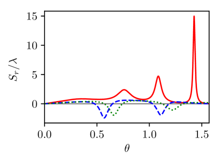
The strength of the microwave drive field depends on magnitude of an external magnetic field (). From steady-state dynamical values (See Eq. (II)), it is evident that all excitation modes strongly depend on the strength of the microwave drive field via . Similarly, the effective magnomechanical coupling coefficient is directly proportional to at fixed . As a result, the output spectrum of the probe field is modified by the strength of the microwave drive field. We recall that, when is kept zero, the intracavity medium becomes transparent to the probe light beam at effective resonance . In order to see this effect on GHS, we plot the GHS as a function of probe light incident angle (in the units of radian) in Fig. 3 at resonance condition. It can be seen from the red curve that GHS shift is always positive in the absence of microwave driving and exhibits three peaks. The peak of GHS gets enhanced at larger incident angle and is maximum at . This means that the group index of the cavity remains positive for each incident angle of the probe light [33].
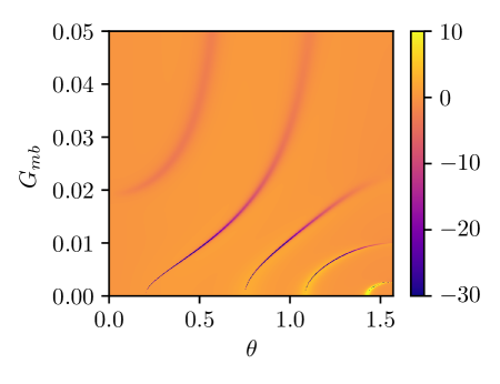
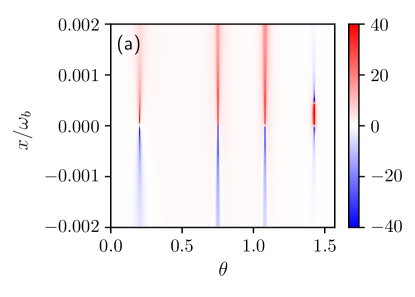
When the effective magnomechanical coupling is turned on through external microwave drive field, the absorption at resonance starts to appear (See Fig. 2). The dashed and dotted curves in Fig. 3 show GHS at MHz and MHz, respectively. The other parameters are the same. We note negative GHS in the reflected probe light beam at certain incident angles . It is already established that the GHS in the reflected beam is negative for absorptive medium [51]. The increase of reduces the amplitude of the negative peaks and peaks gets shifted to higher angle. Therefore, in order to understand this effect more clearly, we present the contour plot of GHS as function of and angle in Fig. 4. The large negative GHS can be obtained at lower values of . Therefore, GHS can be coherently switched from positive to negative via external microwave drive field.
III.2 Effects of Detuning
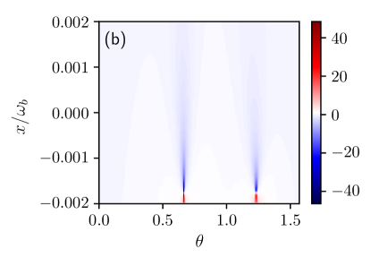
Next, we consider the effect of another control parameter, the effective cavity detuning on the reflected GHS. Figure 5 shows the dependence of the GHS on the effective cavity detuning and incident angles. We observe the manipulation effect on GHS under different strengths of microwave control field. Fig. 5(a) shows the results when is kept zero, which means that there is no influence of the microwave drive field on the cavity. At resonance (), we observe a sharp transition from positive peaks to negative peaks. The magnitude of the GHS is higher at detuning relative to the resonance and eventually gets smaller at larger detuning. These results provide another control-mechanism of the GHS from positive to negative by changing the effective detuning in the absence of microwave drive field. At large incident angle, positive shift appear in a narrow interval of detuning. In Fig. 5(b), we plot the dependence of the GHS on effective cavity detuning and incident angles of the probe light beam in the presence of the microwave control field. We note that the transition point from negative to positive GHS peak moves from resonance to negative effective detuning. As a result, we have negative GHS for a relatively larger range of detuning. Away from the transition point, towards positive detuning, the amplitude of peaks decreases and peaks get broader.
 |
 |
 |
III.3 Effects of weak and strong coupling
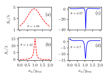
Indeed, our cavity magnomechanical system is a lossy one because the cavity photons have a limited lifetime after which they decay (lose energy) at the cavity decay rate . The cavity decay rate may be different for different microwave cavities depending on its quality factor . Therefore, it may also affect the reflection coefficient as well as the GHS of the reflected probe light beam. Figure 6 shows the behavior of the GHS against the normalized cavity decay rate in units of magnon-phonon coupling at resonance (). The value of ratio defines the coupling regime of the system. For instance, strong coupling regime corresponds to whereas weak coupling regime corresponds to . Figure 6 (a) and (b) shows the results in the absence of microwave drive when at two different angles and , respectively. These two angles correspond to the last two peaks of GHS from Fig. 3 (red curve). We note that the GHS remains positive for the whole range of considered, here. However, it peaks around and decreases symmetrically in the weak and strong coupling regime. This symmetric decrease around becomes very fast, resulting in a narrow spectrum for a larger incident angle (See Fig. 6(b)). Figure 6 (c) and (d) show the results in the presence of microwave drive when MHz and MHz, respectively. We choose the maximum literal shift angle and from the results of Fig. 4. The GHS shift is negative and has dip around . Again, the width of GHS spectrum is narrow at a larger angle.
IV Conclusion
In summary, we have theoretically investigated the GHS in a cavity magnomechanical system where the magnon mode is excited by a coherent microwave control field. We noted the coherent manipulation of the GHS by the control microwave field. The GHS is positive at resonance in the absence of a control field. By turning on the control field, we show that GHS changes from positive to negative. Similarly, by modifying the effective cavity detuning in the absence of a control field, we have shown the behavior of the GHS changing from positive to negative. For instance, positive detuning gives positive GHS while negative detuning gives negative GHS. This symmetric behavior of GHS around resonance, however, can be changed by turning the control field on. We also identify the optimum ratio of microwave photon lifetime to magnon-photon coupling to maximize the GHS. It is shown that the larger incident angles are more sensitive to this optimal ratio as compared to smaller angles. We believe that our proposal and observations may be useful to investigate GHS experimentally in cavity magnomechanical system.
ACKNOWLEDGEMENTS
We acknowledge the fruitful discussions with Dr. Muzammil Shah and Dr. Muhib Ullah.
References
- Zhang et al. [2016] X. Zhang, C.-L. Zou, L. Jiang, and H. X. Tang, Science Advances 2, 1501286 (2016).
- Zhang et al. [2015] D. Zhang, X.-M. Wang, T.-F. Li, X.-Q. Luo, W. Wu, F. Nori, and J. Q. You, npj Quantum Inf 1, 1 (2015).
- Goryachev et al. [2014] M. Goryachev, W. G. Farr, D. L. Creedon, Y. Fan, M. Kostylev, and M. E. Tobar, Phys. Rev. Appl. 2, 054002 (2014).
- Li et al. [2020a] Y. Li, W. Zhang, V. Tyberkevych, W.-K. Kwok, A. Hoffmann, and V. Novosad, Journal of Applied Physics 128, 130902 (2020a).
- Soykal and Flatté [2010] . O. Soykal and M. E. Flatté, Phys. Rev. Lett. 104, 077202 (2010).
- Bai et al. [2015] L. Bai, M. Harder, Y. Chen, X. Fan, J. Xiao, and C.-M. Hu, Phys. Rev. Lett. 114, 227201 (2015).
- Zhang et al. [2014] X. Zhang, C.-L. Zou, L. Jiang, and H. X. Tang, Phys. Rev. Lett. 113, 156401 (2014).
- Li et al. [2018] J. Li, S.-Y. Zhu, and G. Agarwal, Phys. Rev. Lett. 121, 203601 (2018).
- Hussain et al. [2022] B. Hussain, S. Qamar, and M. Irfan, Physical Review A 105, 063704 (2022).
- Li et al. [2019] J. Li, S.-Y. Zhu, and G. S. Agarwal, Phys. Rev. A 99, 021801 (2019).
- Li et al. [2023] J. Li, Y.-P. Wang, J.-Q. You, and S.-Y. Zhu, National Science Review 10, nwac247 (2023).
- Yuan et al. [2020] H. Yuan, P. Yan, S. Zheng, Q. He, K. Xia, and M.-H. Yung, Phys. Rev. Lett. 124, 053602 (2020).
- Li et al. [2020b] X. Li, W.-X. Yang, T. Shui, L. Li, X. Wang, and Z. Wu, Journal of Applied Physics 128, 233101 (2020b).
- Kong et al. [2019] C. Kong, B. Wang, Z.-X. Liu, H. Xiong, and Y. Wu, Opt. Express 27, 5544 (2019).
- Wang et al. [2018a] B. Wang, Z.-X. Liu, C. Kong, H. Xiong, and Y. Wu, Opt. Express 26, 20248 (2018a).
- Liu et al. [2019] Z.-X. Liu, H. Xiong, and Y. Wu, IEEE Access 7, 57047 (2019).
- Wen et al. [2019] F. Wen, B. Guo, Y. Geng, F. Yang, and B. Wu, Appl. Phys. Express 12, 072011 (2019).
- Lu et al. [2021] T.-X. Lu, H. Zhang, Q. Zhang, and H. Jing, Phys. Rev. A 103, 063708 (2021).
- Munir et al. [2023] A. Munir, M. Abbas, Ziauddin, W.-M. Liu, and P. Zhang, J. Opt. Soc. Am. B 40, 1756 (2023).
- Ullah et al. [2020] K. Ullah, M. T. Naseem, and . E. Müstecaplıoğlu, Phys. Rev. A 102, 033721 (2020).
- Hou et al. [2015] B. P. Hou, L. F. Wei, and S. J. Wang, Phys. Rev. A 92, 033829 (2015).
- Zhang et al. [2017] X. Y. Zhang, Y. Q. Guo, P. Pei, and X. X. Yi, Phys. Rev. A 95, 063825 (2017).
- Agarwal and Huang [2010] G. S. Agarwal and S. Huang, Physical Review A 81, 041803 (2010).
- Goos and Hänchen [1947] F. Goos and H. Hänchen, Annalen der Physik 436, 333 (1947).
- Picht [1929] J. Picht, Annalen der Physik 395, 433 (1929).
- Wang et al. [2013] X. Wang, C. Yin, J. Sun, H. Li, M. Sang, W. Yuan, Z. Cao, and M. Huang, Applied Physics Letters 103, 151113 (2013).
- Hsue and Tamir [1985] C. W. Hsue and T. Tamir, J. Opt. Soc. Am. A 2, 978 (1985).
- Wang et al. [2008a] Y. Wang, Z. Cao, H. Li, J. Hao, T. Yu, and Q. Shen, Applied Physics Letters 93, 091103 (2008a).
- Chen et al. [2007] C.-W. Chen, W.-C. Lin, L.-S. Liao, Z.-H. Lin, H.-P. Chiang, P.-T. Leung, E. Sijercic, and W.-S. Tse, Appl. Opt. 46, 5347 (2007).
- Declercq et al. [2004] N. F. Declercq, J. Degrieck, and O. Leroy, Applied Physics Letters 85, 4234 (2004).
- Wang [2015] Z. Wang, Journal of Applied Geophysics 122, 122 (2015).
- White and Pask [1977] I. A. White and C. Pask, Applied Optics 16, 2353 (1977).
- Ziauddin et al. [2010] Ziauddin, S. Qamar, and M. S. Zubairy, Physical Review A 81, 023821 (2010).
- Ziauddin and Qamar [2011] Ziauddin and S. Qamar, Physical Review A 84, 053844 (2011).
- Wang et al. [2008b] L.-G. Wang, M. Ikram, and M. S. Zubairy, Physical Review A 77, 023811 (2008b).
- Idrees et al. [2023] M. Idrees, M. Ullah, and L.-G. Wang, Physical Review A 108, 013701 (2023).
- Darkhosh and Sahandi [2022] A. Darkhosh and R. Sahandi, Laser Physics Letters 19, 055207 (2022).
- Ullah et al. [2019] M. Ullah, A. Abbas, J. Jing, and L.-G. Wang, Physical Review A 100, 063833 (2019).
- Khan et al. [2020] A. A. Khan, M. Abbas, Y.-L. Chaung, I. Ahmed, and Ziauddin, Physical Review A 102, 053718 (2020).
- Ghaisuddin et al. [2021] Ghaisuddin, M. Abbas, A. A. Khan, H. Ali, and Ziauddin, Physica Scripta 96, 125104 (2021).
- Shah [2022] M. Shah, Optical Materials Express 12, 421 (2022).
- Shah et al. [2022] M. Shah, A. Akbar, N. A. Khan, Q. Zaman, S. Iqbal, W. Ali, M. Javed, and M. Shah, JOSA B 39, 1082 (2022).
- Shah et al. [2021] M. Shah, M. Sajid, and M. S. Anwar, Physica E: Low-dimensional Systems and Nanostructures 134, 114819 (2021).
- De Haan et al. [2010] V.-O. De Haan, J. Plomp, T. M. Rekveldt, W. H. Kraan, A. A. Van Well, R. M. Dalgliesh, and S. Langridge, Physical Review Letters 104, 010401 (2010).
- Wang et al. [2018b] Y.-P. Wang, G.-Q. Zhang, D. Zhang, T.-F. Li, C.-M. Hu, and J. You, Physical Review Letters 120, 057202 (2018b), publisher: American Physical Society.
- Artmann [1948] K. Artmann, Annalen der Physik 437, 87 (1948), _eprint: https://onlinelibrary.wiley.com/doi/pdf/10.1002/andp.19484370108.
- Li [2003] C.-F. Li, Physical Review Letters 91, 133903 (2003), publisher: American Physical Society.
- Gardiner and Collett [1985] C. W. Gardiner and M. J. Collett, Physical Review A 31, 3761 (1985).
- Chen [2023] F. Chen, Laser Physics Letters 20, 095206 (2023).
- Li et al. [2016] L. Li, W. Nie, and A. Chen, Scientific Reports 6, 35090 (2016).
- Wild and Giles [1982] W. J. Wild and C. L. Giles, Physical Review A 25, 2099 (1982).