Rydberg atomtronic devices
Abstract
Networks of Rydberg atoms provide a powerful basis for quantum simulators and quantum technologies. Inspired by matter-wave atomtronics, here we engineer switches, diodes and universal logic gates. Our schemes control the Rydberg excitation dynamics via the anti-blockade or facilitation mechanism, allowing for much faster devices compared to cold atom systems. Our approach is robust to noise and can be applied to individually trapped atoms and extensive three-dimensional gases. In analogy to electronics, Rydberg atomtronic devices promise to enhance quantum information processors and quantum simulators.
Introduction.— Electrons in Rydberg atoms can be excited to very large principle quantum number [1, 2, 3]. The resulting large dipole moment and polarisability leads to peculiar effects, such as the dipole blockade: within a specific volume, the excitation of more than one atom to the Rydberg state is inhibited due to the aforementioned dipole interaction [4]. Conversely, when the excitation laser is negatively detuned from resonance, an anti-blockade or facilitation effect occurs: a single initial excitation induces more excitations in neighbouring atoms [5]. Combining blockade and facilitation effects together can provide flexible schemes for coherent manipulation of excitations in networks of Rydberg atoms [6, 7]. The inherent physics and the remarkable know-how in coherent atom manipulations [8, 9, 10], networks of Rydberg atoms provide a fruitful and versatile toolbox for quantum simulators and more widely quantum technologies [1, 3, 11, 12, 13, 14]. Rydberg networks also provide a promising basis for quantum information processors [15, 16, 17].
In our approach, we are inspired by atomtronics, which encapsulates the properties of ultra-cold atoms to create circuits via laser fields of different shapes and intensities [18, 19, 20, 21]. In particular, atomic devices such as atomtronic transistors and switches for cold atoms have been proposed [22, 23, 24] and realised [25]. Another vital building block to perform classical analogue or digital computation is the diode. In the same way as electronics, the atomtronic diode has been proposed by bringing doped conducting cold atom systems together [26, 27, 28].
Here, we demonstrate how the aforementioned control of Rydberg excitations can be exploited to conceive specific atomtronic devices in which, instead of matter, the dynamics involve Rydberg excitations. The transfer and control of excitations are conducted via the facilitation mechanism, where an excited state of an atom induces excitations in neighbouring atoms via the van der Waals interaction combined with appropriately chosen frequency detunings. By applying this idea to different networks, we construct specific Rydberg atomtronic schemes analogous to switches and diodes. Further, we construct logic gates such as AND, NOT and NAND, demonstrating that Rydberg atomtronics provides a universal logic gate set.
A key component for these devices, especially for the diode, is the generation of a non-reciprocal or chiral flow of excitations. When considering interactions within two levels of different Rydberg excitations, chiral currents in ring-shaped networks have been induced via phase shifts [29]. In contrast, here we consider the dynamics of the ground state and excited Rydberg state which lacks a coherent hopping interaction. Nonetheless, we can engineer non-reciprocal behaviour by spatially varying the distance and detuning of atoms to create a one-way facilitation mechanism.
Model.— We investigate a network of Rydberg atoms where we denote the atomic ground state as and Rydberg state as with Hamiltonian [3],
| (1) |
Here, is the Rabi frequency, the detuning of the atom for the -Pauli , the van der Waals interaction coefficient, the excitation number operator and the position of the atom. Coupling with the environment for mixed state is modelled with the Lindblad master equation,
| (2) |
We consider two dissipative mechanisms expressed with Lindblad operators: dephasing with rate as well as decay of excitations with rate , where destroys a Rydberg excitation. In the limit of strong dephasing , the atoms rapidly dephase into mixed states [3] and quantum coherences can be neglected.
In this regime, a classical master equation can be derived via a second-order perturbation theory [30, 31]. The evolution of the probabilities of the basis states is given by
| (3) |
with transition rate
| (4) |
We now review two fundamental phenomena observed in Rydberg atoms. First, we illustrate the Rydberg blockade. Let us assume a Rydberg atom in the ground state and detuning . When there are no other excited atoms nearby, the driving will excite the atom. In contrast, if there is an excited Rydberg state within the Rydberg radius , the atom cannot be excited due to the energy shift induced by the van der Waals interaction.
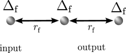
Second, the Rydberg facilitation mechanism induces excitations only when another excitation is present [3]. Let us consider two atoms at the facilitation distance and the facilitation detuning where we choose . When initially none of the atoms are excited, then the detuning will suppress any excitations due to Rabi driving . Now, what happens if the first atom is excited? In this case, the positive van der Waals interaction combined with the negative detuning brings the second atom into resonance, as shown in Fig. 1 and induces its excitation [32]. Repeating this process, the induced excitation can further excite the next atom, effectively creating a facilitation chain of propagating excitations (see Appendix .3) The facilitation mechanism is robust even for strong dephasing noise.
We now apply the blockade and facilitation mechanisms to control the flow of excitations in networks of Rydberg atoms and create various practical devices.
Switch for individually trapped atoms.— A switch is a device that allows current to pass through it whilst it is enabled, however, prevents the transport of current when it is disabled.
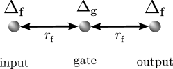
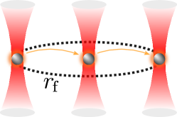
The smallest setup for an atomtronic switch is composed of a one-dimensional chain of atoms with distance , as shown in Fig. 2. We initialise the system with an excitation in the input and all other sites in the ground state. The transport to the output is controlled by a gate atom with variable detuning . When we choose , the gate atom is excited by the input via the facilitation mechanism, while otherwise, the gate atom remains with high probability in the ground state. Hence, if the gate atom is excited, the facilitation mechanism induces excitations in the output.
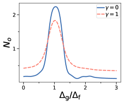
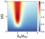
In Fig. 3, we vary the gate detuning and measure the average number of excitations in the output after a specific evolution time (see Appendix .4). We observe that our device behaves like a switch, with a peak in output excitations for , while away from the facilitation regime excitations cannot reach the output. The dynamics are robust against dephasing and decay .
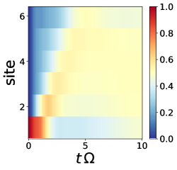
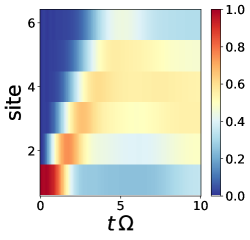
Switch for three-dimensional gas.— Next, we consider Rydberg atoms trapped in a three-dimensional potential without individual control over the position. As shown in Fig. 4, we have a cylindrical trap of length and radius , where the minimal distance between atoms is .
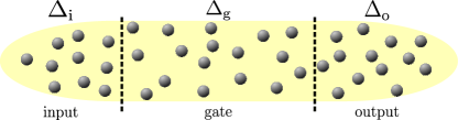
All atoms are subject to the same driving strength and are initialised in the ground state. The system along the direction is split into three regions: input of length , gate of length and output of length . Each region has a different detuning frequency : in the input, we excite Rydberg atoms on resonance with . In the gate, we have either when the switch is on, else we set to block any transport of excitations. In the output, we set the detuning to the facilitation regime . For the gate to block transport, must be larger than the facilitation radius , else excitations in the input can directly excite the output. We simulate the dynamics using the classical approximation Eq. (3) by Monte-Carlo sampling of trajectories where we confirm the validity of the strong dephasing approximation in Appendix .2.
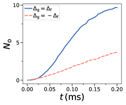

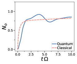
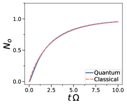
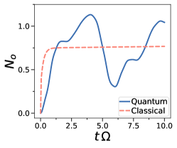
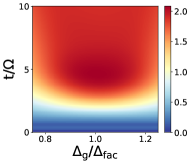
The dynamics of the excitations in the output are shown in Fig. 5. Our simulation parameters are chosen closely to the ones from the Rubidium atom experiment in Ref. [5]. For an enabled switch with we observe twice as many excitations compared to the disabled switch with . This behaviour is robust in the presence of strong dephasing and excitation loss.
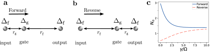
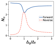
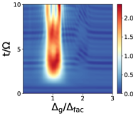
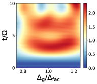
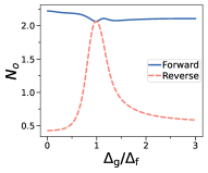
Diode.— The diode is a non-reciprocal device that allows current to pass through from one direction, but blocks transport coming from the reverse direction. To induce non-reciprocal behaviour, we consider a one-dimensional facilitation chain with equal spacing to its neighbours, except for a single gate atom with detuning and distance to either its left or right neighbour (see Fig. 6). First, in Fig. 6a we consider the forward direction operation of the diode. When the gate atom has distance to its left neighbour, an initial excitation in the input can travel via the gate to the output as the facilitation condition is met along the way. In contrast, we consider the reverse direction of the diode in Fig. 6b, where the gate atom has distance to its right neighbour. Then, the facilitation condition is not met between the gate and output atom, blocking any transport. We set the detuning of the gate atom (see Appendix .5) and evolve the system for different values of . Fig. 6c shows the number of excitations in the output at . We find that the forward direction transports a large number of excitations compared to the reverse operation of the diode. The difference between forward and reverse decreases with increasing , but remains relatively large even when is in the same order as the driving frequency .
 a
a
 b
b
 c
c
 d
d

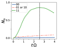
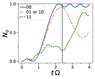
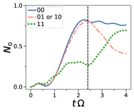
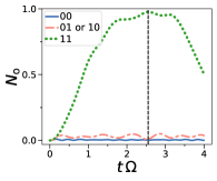
Logic gates.— We now construct different logic gates using the Rydberg interactions. Logic gates return a binary outcome depending on given input bits. For the input, we define logic as a Rydberg atom in the ground state, while corresponds to an excited input atom. We define the logic output as when , while corresponds to , where is a threshold number of excitations.
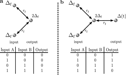
The AND gate returns only when two inputs are , else . We construct the AND gate with three atoms as seen in Fig. 7a. The two input atoms are at a distance to the output atom, while the detuning of the output atom is chosen as , i.e. twice the original facilitation condition. Only when both input atoms are excited, the output atom is on resonance due to the van der Waals interaction.
Next, we consider the NAND gate, which is an inverted AND gate, i.e. it returns only when the two inputs are . We realise the NAND gate by combining the AND gate with a NOT gate (see Fig. 7b). The NOT gate flips to and vice versa. In our setup, we realise the NOT gate by setting the detuning on the output atom to for a time period at , and for all other times. Together with the constant Rabi driving, this realises a pulse which excites the ground state to a Rydberg state and de-excites an initial Rydberg state into the ground state. We create a NAND gate by applying a NOT gate on an additional atom which is at facilitation distance to the output of the AND gate.
We show the AND gate and NAND gate in Fig. 8. We show the average number of excitations in the output against time for different input excitations. We observe that the logic table of the AND (Fig. 8a,b) and NAND gate (Fig. 8c,d) can be realised by reading out . We find that a threshold is sufficient to distinguish between and even in the presence of noise. We find the optimal work time as dashed lines where we find optimal performance for the gates.
Discussion.— We have demonstrated that networks of Rydberg atoms can create atomtronic devices that, instead of matter-wave, are based on a controlled flow of excitations. The flow is controlled by using the blockade and facilitation mechanism of interacting Rydberg atoms. This way, a new platform of atomtronic circuits is proposed. The propagation of matter-wave in typical cold atoms clouds occurs on the millisecond scale, whereas Rydberg excitations can travel in microseconds. Therefore, Rydberg excitations have the potential to provide proof for fast atomtronic quantum devices.
With this approach, we have demonstrated different circuit elements providing the Rydberg atomtronics counterpart of classical electronic devices as switches and diodes. In particular, diodes require non-reciprocal transport which commonly is implemented by breaking time-reversal symmetry via the flux [29]. In contrast, we engineer non-reciprocal transport by using the facilitation mechanism combined with non-uniform atomic distances. Further, by using the facilitation condition involving multiple atoms we implement AND, NOT and NAND classical gates, realising a universal logic gate set. Future work can combine our different gates and devices to create even more complex gadgets such as adders or routers. Our proposed devices use experimentally demonstrated parameter regimes and thus can be realised in state-of-the-art experiments for tweezer arrays of Rydberg atoms and three-dimensional gases.
Note added.— While writing the manuscript, a similar mechanism to engineer non-reciprocal transport via facilitation has been proposed [33].
Acknowledgements.
Acknowledgements.— We thank Leong-Chuan Kwek, Wenhui Li, Francesco Perciavalle, Enrico Domanti, Wayne J. Chetcuti, Davide Rossini and Thibault Vogt for discussions. The Julian Schwinger Foundation grant JSF-18-12-0011 is acknowledged. OM and AL also acknowledge support by the H2020 ITN “MOQS” (grant agreement number 955479) and MUR (Ministero dell’Università e della Ricerca) through the PNRR MUR project PE0000023-NQSTI.References
- Browaeys and Lahaye [2020] A. Browaeys and T. Lahaye, Many-body physics with individually controlled rydberg atoms, Nature Physics 16, 132 (2020).
- Adams et al. [2019] C. S. Adams, J. D. Pritchard, and J. P. Shaffer, Rydberg atom quantum technologies, Journal of Physics B: Atomic, Molecular and Optical Physics 53, 012002 (2019).
- Morsch and Lesanovsky [2018] O. Morsch and I. Lesanovsky, Dissipative many-body physics of cold rydberg atoms, La Rivista del Nuovo Cimento 41, 383 (2018).
- Comparat and Pillet [2010] D. Comparat and P. Pillet, Dipole blockade in a cold rydberg atomic sample, JOSA B 27, A208 (2010).
- Valado et al. [2016] M. Valado, C. Simonelli, M. Hoogerland, I. Lesanovsky, J. P. Garrahan, E. Arimondo, D. Ciampini, and O. Morsch, Experimental observation of controllable kinetic constraints in a cold atomic gas, Physical Review A 93, 040701 (2016).
- Leonhardt et al. [2014] K. Leonhardt, S. Wüster, and J. Rost, Switching exciton pulses through conical intersections, Physical review letters 113, 223001 (2014).
- Gutiérrez et al. [2017] R. Gutiérrez, C. Simonelli, M. Archimi, F. Castellucci, E. Arimondo, D. Ciampini, M. Marcuzzi, I. Lesanovsky, and O. Morsch, Experimental signatures of an absorbing-state phase transition in an open driven many-body quantum system, Physical Review A 96, 041602 (2017).
- Endres et al. [2016] M. Endres, H. Bernien, A. Keesling, H. Levine, E. R. Anschuetz, A. Krajenbrink, C. Senko, V. Vuletic, M. Greiner, and M. D. Lukin, Atom-by-atom assembly of defect-free one-dimensional cold atom arrays, Science 354, 1024 (2016).
- Barredo et al. [2016] D. Barredo, S. De Léséleuc, V. Lienhard, T. Lahaye, and A. Browaeys, An atom-by-atom assembler of defect-free arbitrary two-dimensional atomic arrays, Science 354, 1021 (2016).
- Schymik et al. [2020] K.-N. Schymik, V. Lienhard, D. Barredo, P. Scholl, H. Williams, A. Browaeys, and T. Lahaye, Enhanced atom-by-atom assembly of arbitrary tweezer arrays, Physical Review A 102, 063107 (2020).
- Bluvstein et al. [2021] D. Bluvstein, A. Omran, H. Levine, A. Keesling, G. Semeghini, S. Ebadi, T. T. Wang, A. A. Michailidis, N. Maskara, W. W. Ho, et al., Controlling quantum many-body dynamics in driven rydberg atom arrays, Science 371, 1355 (2021).
- Bernien et al. [2017] H. Bernien, S. Schwartz, A. Keesling, H. Levine, A. Omran, H. Pichler, S. Choi, A. S. Zibrov, M. Endres, M. Greiner, et al., Probing many-body dynamics on a 51-atom quantum simulator, Nature 551, 579 (2017).
- Barredo et al. [2015] D. Barredo, H. Labuhn, S. Ravets, T. Lahaye, A. Browaeys, and C. S. Adams, Coherent excitation transfer in a spin chain of three rydberg atoms, Physical review letters 114, 113002 (2015).
- Chen et al. [2023] C. Chen, G. Bornet, M. Bintz, G. Emperauger, L. Leclerc, V. S. Liu, P. Scholl, D. Barredo, J. Hauschild, S. Chatterjee, et al., Continuous symmetry breaking in a two-dimensional rydberg array, Nature 616, 691 (2023).
- Saffman et al. [2010] M. Saffman, T. G. Walker, and K. Mølmer, Quantum information with rydberg atoms, Reviews of modern physics 82, 2313 (2010).
- Cong et al. [2022] I. Cong, H. Levine, A. Keesling, D. Bluvstein, S.-T. Wang, and M. D. Lukin, Hardware-efficient, fault-tolerant quantum computation with rydberg atoms, Physical Review X 12, 021049 (2022).
- Lukin et al. [2001] M. D. Lukin, M. Fleischhauer, R. Cote, L. Duan, D. Jaksch, J. I. Cirac, and P. Zoller, Dipole blockade and quantum information processing in mesoscopic atomic ensembles, Physical review letters 87, 037901 (2001).
- Seaman et al. [2007a] B. Seaman, M. Krämer, D. Anderson, and M. Holland, Atomtronics: Ultracold-atom analogs of electronic devices, Physical Review A 75, 023615 (2007a).
- Amico et al. [2005] L. Amico, A. Osterloh, and F. Cataliotti, Quantum many particle systems in ring-shaped optical lattices, Physical review letters 95, 063201 (2005).
- Amico et al. [2022] L. Amico, D. Anderson, M. Boshier, J.-P. Brantut, L.-C. Kwek, A. Minguzzi, and W. von Klitzing, Colloquium: Atomtronic circuits: From many-body physics to quantum technologies, Reviews of Modern Physics 94, 041001 (2022).
- Amico et al. [2021] L. Amico, M. Boshier, G. Birkl, A. Minguzzi, C. Miniatura, L.-C. Kwek, D. Aghamalyan, V. Ahufinger, D. Anderson, N. Andrei, et al., Roadmap on atomtronics: State of the art and perspective, AVS Quantum Science 3, 039201 (2021).
- Gajdacz et al. [2014] M. Gajdacz, T. Opatrnỳ, and K. K. Das, An atomtronics transistor for quantum gates, Physics Letters A 378, 1919 (2014).
- Stickney et al. [2007] J. A. Stickney, D. Z. Anderson, and A. A. Zozulya, Transistorlike behavior of a bose-einstein condensate in a triple-well potential, Physical Review A 75, 013608 (2007).
- Wilsmann et al. [2018] K. W. Wilsmann, L. H. Ymai, A. P. Tonel, J. Links, and A. Foerster, Control of tunneling in an atomtronic switching device, Communications physics 1, 91 (2018).
- Caliga et al. [2016] S. C. Caliga, C. J. Straatsma, and D. Z. Anderson, Transport dynamics of ultracold atoms in a triple-well transistor-like potential, New Journal of Physics 18, 025010 (2016).
- Pepino et al. [2009] R. Pepino, J. Cooper, D. Anderson, and M. Holland, Atomtronic circuits of diodes and transistors, Physical review letters 103, 140405 (2009).
- Pepino et al. [2010] R. Pepino, J. Cooper, D. Meiser, D. Anderson, and M. Holland, Open quantum systems approach to atomtronics, Physical Review A 82, 013640 (2010).
- Seaman et al. [2007b] B. Seaman, M. Krämer, D. Anderson, and M. Holland, Atomtronics: Ultracold-atom analogs of electronic devices, Physical Review A 75, 023615 (2007b).
- Perciavalle et al. [2023] F. Perciavalle, D. Rossini, T. Haug, O. Morsch, and L. Amico, Controlled flow of excitations in a ring-shaped network of rydberg atoms, Physical Review A 108, 023305 (2023).
- Lesanovsky and Garrahan [2013] I. Lesanovsky and J. P. Garrahan, Kinetic constraints, hierarchical relaxation, and onset of glassiness in strongly interacting and dissipative rydberg gases, Physical review letters 111, 215305 (2013).
- Marcuzzi et al. [2014] M. Marcuzzi, J. Schick, B. Olmos, and I. Lesanovsky, Effective dynamics of strongly dissipative rydberg gases, Journal of Physics A: Mathematical and Theoretical 47, 482001 (2014).
- Lesanovsky and Garrahan [2014] I. Lesanovsky and J. P. Garrahan, Out-of-equilibrium structures in strongly interacting rydberg gases with dissipation, Physical Review A 90, 011603 (2014).
- Valencia-Tortora et al. [2023] R. J. Valencia-Tortora, N. Pancotti, M. Fleischhauer, H. Bernien, and J. Marino, A rydberg platform for non-ergodic chiral quantum dynamics, arXiv:2309.12392 (2023).
Appendix
.1 Experimental Consideration
Considering the experimental creation, we assume the same experimental procedure that is noted in [3]. Here atoms are excited from the ground to the Rydberg state via a two-photon transition as they share the same parity [31]. The first of which, , a laser with excites the atom to an intermediate state. Then from here, another transition occurs, due to a laser with , this excites the atom from , the Rydberg state.
We chose our simulation parameters in close accordance with experimental work conducted on Rubidium atoms [5, 3]. We select to use parameters with values: MHz, kHz, MHz and GHz. We decide to work in units of and covert the other parameters accordingly. We convert the dephasing, , the decay, . For the interaction, we fix the values of MHz and therefore . We provide these values to a similar range to that of experimental work.
For our systems, we consider detuning with spatial variation. In practice, such conditions can be implemented by suitably shifting the excitation laser frequency (for example through an acousto-optic modulator) and then by exciting specific portions of the Rydberg network with different frequencies.
.2 Classical equation vs full simulation
Here we compare the simulation with the full quantum equations Eq. (2) against the classical approximation Eq. (3), derived for the limit of strong dephasing . For the system in Fig. 9, both the dynamics are represented in Fig. 10. We observe that for , the classical equations are a good approximation to the full quantum dynamic. Beyond this limit, , the quantum coherence between the atoms becomes too large, therefore there is a discrepancy between the two evolutions.
 a
a
 b
b
 c
c


.3 Transport
We study the transport in a linear chain of Rydberg atoms as shown in Fig. 9. We set the inter-atom distance to the facilitation radius and detuning . We evolve the system with an initial excitation in the input.
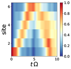
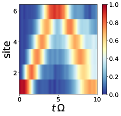
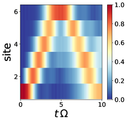
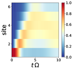
The dynamics of excitations are shown in Fig. 11. In the quantum regime, we consider two cases: and . We observe a propagation of excitation throughout the sites and then a ”back-reflection” towards the input. In this situation, the individual atoms transition between the ground and Rydberg state via the Rabi driving frequency, . The interaction, , plays an additional role in the correlation in the interaction term, resulting in the excitation being back-reflected at every site.
With increasing dephasing , the back reflection is less dominant in the dynamics as the excitation density decreases with increasing propagation distance. We also find that after becoming excited, the atoms are not driven directly to the ground state due to the dephasing destroying the coherence of the state.
 a
a
 b
b
 c
c
 d
d
 e
e
 f
f


.4 Switch
We elaborate on how we determine the optimal time to read out the switch. The goal is to find the time when we have maximal density in the output. We evolve our atom switch via Eq. (2) for and record the density of excitations at each time increment. The results are shown in Fig. 12. We now regard the regime where the switch is on by zooming into dynamics where . We find that the maximum does not vary much with in this regime. We identify the time with maximum density for , which occurs at time and respectively for and .
 a
a
 b
b
 c
c
 d
d


.5 Diode
We now identify a good choice for gate detuning for the individually trapped diode. We evolve the diode with atoms for in both the forward and reverse direction. We measure the number of excitations in the output at () with (without) dephasing. We choose these times as here we find the highest number of excitations for the forward direction as studied previously for the switch. We show against in Fig. 13. Note that the modified distance depends on . For , there is no difference between forward and reverse direction, thus this parameter regime cannot be used for a diode. In contrast, we find a large difference between forward and reverse away from this point. Therefore, we consider the diode with .
 a
a
 b
b