Coded Caching Scheme for Partially Connected Linear Networks Via Multi-antenna Placement Delivery Array ††thanks: M. Cheng, Y. Xie and M. Zhang are with Guangxi Key Lab of Multi-source Information Mining Security, Guangxi Normal University, Guilin 541004, China (e-mail: chengqinshi@hotmail.com, yunxie1022@stu.gxnu.edu.cn, ztw_07@foxmail.com,). ††thanks: Z. Huang and Y. Wu are with the School of Information Science and Technology, ShanghaiTech University, Shanghai 201210, China (e-mail: huangzhh,wuyl1@shanghaitech.edu.cn).
Abstract
In this paper, we study the coded caching scheme for the partially connected linear network, where there are files each of which has an equal size, transmitters and users; each user and transmitter caches at most and files respectively; each user cyclically communicates with transmitters. The goal is to design caching and delivery schemes to reduce the transmission latency measured by the metric normalized delivery time (NDT). By delicately designing the data placement of the transmitters and users according to the topology, we show that a combinatorial structure called multiple-antenna placement delivery array (MAPDA), which was originally proposed for the multiple-input single-output broadcast channels, can be also used to design schemes for the partially connected linear network. Then, based on existing MAPDAs and our constructing approach, we propose new schemes that achieve the optimal NDT when and smaller NDT than that of the existing schemes when (, ) or (). Moreover, our schemes operate in one-shot linear delivery and significantly reduce the subpacketizations compared to the existing scheme, which implies that our schemes have a wider range of applications and lower complexity of implementation.
Index Terms:
Coded caching, Multiple-antenna placement delivery array, normalized delivery time, partially connected linear network.I Introduction
The immense growth of wireless data traffic is putting incredible pressure on the wireless network, especially the high temporal variability of network traffic, resulting in congestion during peak traffic time and under utilization during off-peak time. Coded caching in [1] is an efficient solution to reduce transmission pressure by pre-populating the user’s local cache with content at off-peak time and using coding theory to generate more multicast opportunities during peak traffic time.
A caching system consists of two phases, i.e., the placement phase at off-peak traffic time and the delivery phase at peak traffic time. In the placement phase, the server places content in each user’s cache without knowing future users’ demands. In the delivery phase, each user requests an arbitrary file and the server broadcasts coded packets such that each user can decode its requested file with the help of its caching contents. The first coded caching scheme was proposed by Maddah-Ali and Niesen in [1] for a shared-link broadcast network, where a central server containing files with equal length connects to users, each of which can cache at most files through an error-free shared link. The communication goal is to design a scheme such that the transmission cost is as small as possible. The first coded caching scheme, referred to as the MN scheme, achieves the minimum communication load (i.e., the number of communication bits normalized by the size of the file) within a multiplicative factor of 2[2]. For the uncoded placement where each user stores directly a subset of the bits of files, the MN is exactly optimal [3, 4]. Following the original caching problem, many works have investigated the coded caching problem for a variety of network topologies, such as Device-to-Device (D2D) network [5, 6, 7], hierarchical network [8, 9, 10], combination network [11, 12, 13], and arbitrary multi-server linear network [14], etc.
Recently, coded caching has been widely extended to the wireless network, such as multiple-input single-output (MISO) broadcast channels [15, 16, 17, 18, 19, 20, 21, 22], multiple-input multiple-output (MIMO) broadcast channels [23], single-input-single-output (SISO) interference channels [24, 25, 26, 27, 28, 29], and MIMO interference channels [30, 31], etc. The goal of most existing works on cache-aided wireless network is to jointly design data placement and physical layer delivery to improve the communication efficiency. For instance, [24, 25, 26] proposed schemes that are (order) optimal in the sense of sum DoF for the cache-aided SISO interference channels, and [29] established the optimal normalized delivery efficiency (NDT), a definition first introduced by [32], in certain cache size regions. The work in [28] studied a partially connected linear network where the users can only connect with part of the transmitters, and proposed a coded caching scheme that achieves the optimal NDT when cache memories of transmitters and users are relatively large. In addition, some works take both communication efficiency and computational complexity into consideration. For example, low-subpacketisation coded caching schemes generated by constructing the multiple-antenna placement delivery array (MAPDA)111The authors independently proposed the same combinatorial structure called extended placement delivery array for MISO broadcast channels. were proposed in [17, 18, 21, 22] for MISO broadcast channels, and one-shot linear delivery based on interference zero-forcing was proposed in [24] for SISO interference channels.
In this paper, we revisit the partially connected linear network [28] that models a typical wireless network where some users can only communicate with a subset of transmitters due to pass loss caused by blocking objects. More specifically, we consider a wireless network with linearly aligned users, linearly aligned transmitters, and each user is locally connected to a subset of continuous transmitters. Let and represent the caching memory sizes of each user and transmitter, respectively. In [28], a coded caching scheme based on interference alignment and interference neutralization was proposed by Xu, Tao, and Zheng, namely the XTZ scheme, to achieve the optimal NDT when . Despite the optimality of the scheme in the case , there are still several important and unresolved issues. First, it is unknown whether the optimality still holds for the case , which is a common case when each user and transmitter are equipped with insufficient size of cache memories; if the answer is not, then how can we further improve the communication efficiency? Second, the XTZ scheme involves high coding and computational complexity. More specifically, for the case , the XTZ scheme splits each file into an exponentially large number of subfiles and applies interference alignment, which requires each user to first wait
transmission slots where 222In general, the value should be sufficiently large such that the maximum degree of freedom is achieved. and to decode its desired contents. This would cause unbearable waiting latency and high computational complexity in the transmit beamforming vector design (See detailed discussions in Section III-A.)
In view of the facts above, we aim to find low-complexity and communication-efficient coded caching schemes for the partially connected wireless network, to simultaneously reduce the subpacketisation level, computational complexity, and transmission latency. The contributions of our work can be summarized as follows.
We first prove that MAPDA can also be used to design coded caching schemes for the partially connected wireless network, and then propose new coded caching schemes based on existing MAPDAs, which are listed in Table II. Note that the MAPDA was originally proposed for wireless network where all users connect with all transmitters, and directly applying MAPDA to the partially connected wireless network would lead to the users missing some signals due to disconnecting links. To address this issue, we delicately design the data placement at the transmitters via a cyclic-based MAPDA such that any consecutive transmitters can store and deliver all required contents to their connected users, and then globally design all the users’s placement based on an integral MAPDA. This enables our scheme to simultaneously deliver all desired files to all users and achieve larger multicast opportunities compared to the XTZ scheme.
Compared with the XTZ scheme, our schemes achieve smaller NDTs when 1) , or 2) ; the same NDT as the XTZ scheme when (optimal NDT is achieved) or ; and slightly larger NDTs than the XTZ scheme when and but preserving much lower decoding complexity due to the one-shot delivery strategy (see Table III).
Unlike the XTZ scheme where the subpacketization grows exponentially with , our schemes significantly reduce the subpacketization that linearly increases with . Moreover, our scheme enables independent data placement between the transmitter and user, while the XTZ scheme requires data placements among all nodes to be dependent on each other. Finally, our schemes operate in a one-shot delivery strategy for all cases, while the XTZ scheme needs all users to wait for long transmission slots and then decode the information for some cases (e.g., ). These facts indicate that our schemes have a wider range of applications and lower complexity of implementation (see Section III-A3).
Paper Organization
The rest of this paper is organized as follows. Section II describes the system model. Section III present MAPDA for the partially connected linear network. Some proofs can be found in Section IV and Appendices.
Notations: In this paper, the following notations will be used unless otherwise stated.
and . denotes the cardinality of a set.
We use the notation if is divisible by and otherwise. If is not divisible by , denotes the least non-negative residue of modulo ; otherwise, .
denotes the greatest common divisor of and .
Let be a set with , for any , denotes the smallest element of , i.e., .
For any positive integers and with , let , i.e., is the collection of all -sized subsets of .
Let be a vector with length , for any , denotes the coordinate of . For any subset , denotes a vector with length obtained by taking only the coordinates with subscript .
Given any array , for any integers and , represents the element located in the row and the column of ; represents the subarray generated by the row indices in and the columns indices in . In particular let be shortened by and be shortened by .
II Partially Connected Networks placement Delivery Array
II-A System Model
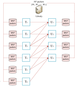
Consider a partially connected linear network (see Fig. 1), where there is a library of files each of -bit length, linearly aligned transmitters denoted by T1, T2, , TK+L-1, linearly aligned users denoted by U1, U2, , UK, and each user Uk is connected to consecutive transmitters Tk, Tk+1, , Tk+L-1 where and . Here, is referred to as user connectivity. Fig. 1 shows an example of the linear network with and where each transmitter is equipped with a cache of finite size and has a single antenna. A coded caching scheme contains two phases.
II-A1 Placement phase
In this paper, we consider the uncoded placement where every node directly caches a subset of the library bits. Each file is divided into packets, i.e., , where each packet for . Here represents the size of each packet. Clearly, we have . Each transmitter and each user caches some packets of with a size of at most packets and packets, respectively. Denote the cached contents at transmitter Tj where and user Uk where as and , respectively.
We assume that the placement is performed without knowing users’ later demands.
II-A2 Delivery phase
Each user Uk requests for an arbitrary file from the library , for . Let denote the demand vector. According to the users’ demands and caches, the server transmits coded packets through antennas. More precisely, the server first uses a code for the Gaussian channel with the rate
| (1) |
to encode each packet to a coded packet as , where is the coding scheme for the Gaussian channel, e.g., random Gaussian coding. Here each coded packet contains complex symbols and carries one degree-of-freedom (DoF). The whole communication process contains blocks, each of which consists of complex symbols (i.e., time slots). In each block , the communication goal is to deliver a subset of the requested packets, denoted by , to a subset of users . Assume that the user U requests the packet for each . In this paper we only consider linear coding schemes in the delivery phase. In each block , each transmitter Tj where sends , which is linear combinations of the coded plackets, i.e.,
where is the complex beam forming coefficient and can be any complex value if the packet is cached by transmitter Tj, otherwise for each . Then each user , can receive the following signal
| (2) |
through the interference channel where denotes the channel coefficient from transmitter Tj to user Uk, which is independent and identically distributed in . User can decode the following coded signal
based on its local caches and received signal . By assuming is large enough, the coded packet can be decoded with an error probability exponentially decreasing to zero. To evaluate the transmission efficiency of the scheme, we adopt the same metric normalized delivery latency (NDT) as in [27, 28], which is defined as
| (3) |
where is the total time slots in the whole communication process. Since each file contains packets, each of which has bits and there are in total time slots, (3) can be written as
| (4) |
From (II-A2), NDT can represent the maximal normalized number of transmitted files over all possible demands in the interference channel and the high signal-to-noise ratio (SNR) regime. We prefer to design a scheme with the optimal NDT defined as
Remark 1:
The first coded caching scheme for the partially connected linear network was proposed in [28], where the following result was given.
Lemma 1 (NDT of the XTZ scheme [28]):
For the cache-aided partially connected linear network, there exists a coded caching scheme with the NDT as follows.
| (12) |
II-B Multi-antenna Placement Delivery Array
The authors in [21] proposed multiple-antenna placement delivery array (MAPDA) to characterize the placement strategy and delivery strategy for the MISO caching system. In this section, we will introduce MAPDA that will be helpful in generating schemes for the partially connected linear network.
Definition 1 ([21]):
For any positive integers , , , and , an array that is composed of and is called multiple-antenna placement delivery array (MAPDA) if it satisfies the following conditions
-
C.
The symbol appears times in each column;
-
C.
Each integer occurs at least once in the array;
-
C.
Each integer appears at most once in each column;
-
C.
For any integer , define to be the subarray of including the rows and columns containing , and let denote the dimensions of . The number of integer entries in each row of is less than or equal to , i.e.,
(13)
If each integer appears times in the , then is a g-regular MAPDA, denoted by - MAPDA.
Example 1:
We can check that the array is a - = - MAPDA.
For instance, when , we have the following sub-array.
It can be seen that each row of contains integer entries and no more than integer entries. Hence, satisfies the condition C of Definition 1.
In a MISO caching system, there is a server containing files with the same size, and users each of which has a cache with the capacity of files through antennas over the interference channel. Given a MAPDA , we can obtain a scheme for MISO caching system in the following two phases.
Placement phase: The columns and rows denote the users and packets of each file, respectively. Specifically, the server divides each file into packets; the entry means that the packets of all files are cached by user . Each user caches files by Condition C of the Definition 1. So, if , for and , is an integer , then the packet of each file is not stored by user . Clearly, the placement strategy of the scheme realized by MAPDA is called uncoded cache placement.
Delivery phase: The integer represents delivery strategy at the block . For any demand vector , at block , the server first chooses a pre-coding matrix for antennas to encode the requested packets indicated by , and then sends coded packets to the users.
| Index | MAPDAs | F | |||||||
| 1 | [24]: | ||||||||
| 2 | [15]: | ||||||||
| 3 | [16]: | ||||||||
| 4 | [17]: | ||||||||
| 5 |
|
|
|||||||
| 6 |
|
||||||||
| 7 | [21]: | ||||||||
| 8 |
|
||||||||
| 9 |
|
||||||||
| 10 |
|
||||||||
| * equals to if , and otherwise. | |||||||||
In [21], the authors pointed out that 1) at each block the server multicasts packets requested by different users by Conditions C2-3 of Definition 1; 2) the condition C of Definition 1 ensures that at each block , the server can always find the pre-coding matrices such that each user can recover its requested packet. So, the delivery strategy of the scheme realized by MAPDA is a one-shot linear delivery. Then we can obtain the following result.
Lemma 2 ([21]):
Given MAPDA , there exists an -division scheme for the multiple antennas coded caching problem with memory ratio , sum-DoF and subpacketization .
Under the constraints of uncoded cache placement and one-shot linear delivery, the maximum sum-DoF is upper bounded by [19], which is also an upper bound on the sum-DoF achieved by the caching schemes from MAPDA.
Lemma 3 ([19, 21, 22]):
For the multiple-antenna coded caching scheme with memory ratio generated by a MAPDA, the sum-DoF is no more than .
In the literature, the schemes in [24, 15, 18, 17, 33] can be represented by MAPDAs. So we summarize all the schemes which achieve the sum-DoF by MAPDAs in Table I.
In Table I, it is not difficult to check that the subpacketizations of the first six MAPDAs are exponent with the number of users; the subpacketizations of the last five MAPDAs are linear with the number of users; the second MAPDA is a special case of the fifth scheme; the subpacketizations of the third and fourth MAPDAs are larger than that of the fifth scheme. So in the following we will only use the fifth, sixth, seventh and eighth MAPDAs in Table I.
The authors in [21] also pointed out that MAPDA can also be used for the SISO cache-aided interference channels by viewing the transmitters as transmit antennas. This is because the channel coefficient between any transmitter and user can be chosen independently and identically distributed (i.i.d) from , which enables us to always find a pre-coding matrix for all the transmitters. However, the MAPDA can not be directly applied to design coding schemes for the partially connected linear network since channel coefficients can be chosen independently and identically from only if the transmitter Tj connects to the user Uk, and otherwise. This means that directly applying MAPDA will lead the users not to receive the signals carrying their desired packets, due to the disconnecting link .
III MAPDA for Partially Connected Linear Interference Networks
In this section, we will show that MAPDA can also be used to generate a coded caching scheme for the partially connected linear network by our novel construction and the Schwartz-Zippel Lemma [34], i.e., the following result which is proved in Section IV.
Theorem 1:
Given a MAPDA, there exists a coded caching scheme for the partially connected linear network achieving the NDT with , , and subpacketization .
By Theorem 1 and the fifth, sixth, seventh and eighth MAPDAs in Table I, we have the following schemes for the partially connected linear network.
Theorem 2:
For any positive integers , , and , there exist four coded caching schemes for the partially connected linear network with , , NDT , subpacketization and their parameter limitations listed in Table II.
III-A Performance Analyses
In this subsection, we will show the advantages of our schemes compared to the XTZ scheme in [28] from the point of view of subpacketization, NDT, and complexity in the delivery phase, respectively. Prior to the comparisons, we first introduce the data placement and the delivery strategies of the scheme in [28].
| Parameter limitations | NDTs | |||
III-A1 The placement strategy for users of XTZ scheme in [28]
Given the data placement in MN scheme (i.e., the scheme for the shared-link network with users each with a cache size of files), each user in a partially connected network consecutively chooses a placement method such that the placement method chosen for any consecutive of users follows exactly the placement strategy of the MN scheme. Here we summarize the subpacketization of XTZ scheme in [28] as follows.
| (14) |
From (14), we observe that the XTZ scheme requires a subpacketization that grows exponentially with .
By Table II, the subpacketization of our schemes is small or linear with the number of users for some parameters, instead of exponentially increasing in the XTZ scheme, which demonstrates the advantage of the small subpacketizations.
Unlike the XTZ scheme that takes consecutive users at a time and uses -user MN data placement, our data placement is determined by the stars in a MAPDA, which implies that our schemes globally design the placement and delivery among all the users. Naturally, our schemes could improve the NDT of the XTZ scheme for some parameters as the global design among all users’ data placement could potentially create larger multicast opportunities. By theoretical comparisons, we have Table III whose proof is included in Appendix B.
By Table III, we can see that our schemes reduce the NDT compared to the XTZ scheme when or and ; when our scheme has the same optimal NDT as the XTZ scheme. Let us also take a numerical comparison to verify our claim in Table III. When , , and , we can obtain the NDTs of our schemes in Theorem 2 and the XTZ scheme respectively, as listed in Fig.2.
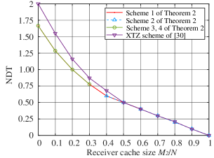
We can see that the NDTs of Scheme 1, Scheme 3, and Scheme 4 are smaller than the NDT of the XTZ scheme when , which is corresponding to the conditions in the second and third row of Table III. Recall that the XTZ scheme already achieves the optimal NDT when for the condition in first row of Table III. Clearly, Scheme 1 and Scheme 2 also have the same NDT which implies that they are also optimal.
Finally, by Table IV we can see that there exist some schemes in Theorem 2 having both smaller NDT and subpacketizations than those of the XTZ schemes.
| subpacketization | NDT | |||||||||
| XTZ scheme | Theorem | XTZ scheme | Theorem | |||||||
| (14) | Scheme 1 | Scheme 2 | Scheme 3 | Scheme 4 | (1) | |||||
| 10 | 0.2 | 0.2 | 5 | 25 | 50 | 25 | 100 | 1.04 | 2 | |
| 10 | 0.33 | 0.33 | 6 | 180 | 300 | 60 | 180 | 1 | 1 | |
| 10 | 0.67 | 0.33 | 6 | 90 | 420 | 60 | 0.6 | 0.6 | ||
| 10 | 0.33 | 0.4 | 6 | 180 | 120 | 60 | 120 | 0.84 | 0.75 | |
| 50 | 0.1 | 0.1 | 10 | 100 | 200 | 100 | 900 | 1.26 | 4.5 | |
| 50 | 0.1 | 0.4 | 10 | 2100 | 200 | 2100 | 900 | 0.66 | 4.5 | |
| 100 | 0.2 | 0.2 | 50 | 8.7E19 | 500 | 2500 | 1000 | 2 | 2 | |
| 100 | 0.4 | 0.2 | 50 | 2.8E22 | 750 | 750 | 1500 | 1.33 | 1.33 | |
| 100 | 0.5 | 0.5 | 100 | 5.1E30 | 400 | 5000 | 0.5 | 0.5 | ||
III-A2 The placement strategy for transmitters of XTZ scheme in [28]
For the placement strategy of the transmitters, when each of every consecutive transmitters caches a distinct part of each file. This is the same as our placement strategy for the transmitters. When the placement strategy for the transmitters relies on the placement strategy for the users. Clearly, our placement strategy for the transmitters is independent to the placement strategy for the users.
III-A3 The delivery strategy of XTZ scheme in [28]
In the delivery phase of the XTZ scheme, the computational complexity mainly comes from the design of the precoding matrices and decoding matrices to align or neutralize the interference in the communication[28]. Specifically, it requires the users to first wait for multiple transmission slots and then compute the decoding matrices, which are the inverse of the multiplication of channel coefficients matrices and the precoding matrices. For example, for the case , the XTZ scheme applies the interference alignment in transmission that requires in total transmission slots where and . On the contrary, there exists no matrix computation in our schemes due to one-shot binary communication, i.e., the user can directly obtain the desired symbol after every transmission.
III-B Sketch of Construction in Theorem 1
Let us consider a partially connected linear network with . We will show how to generate a coded caching scheme based on -- MAPDA in Example 1. Clearly, is an integer, i.e., the condition in Theorem 1 holds.
Our main construction idea is that we first generate a new -- MAPDA based on and an array called transmitter caching array. Then, we propose the placement strategies for the transmitters and users according to the stars in and , respectively. According to the integers in , the delivery strategy is proposed. So, our method contains constructing two arrays and , and realizing a scheme via and .
III-B1 Constructing and
By placing in Example 1 three times vertically and then increasing the integers in by the occurrence orders (from up to down) of , we have a array as follows.
| (18) |
It is not difficult to check that the obtained array is a -- MAPDA.
Now let us construct the array . As illustrated in Fig. 3,
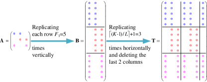
we first construct an square in which each row has cyclic stars, replicate each row of vertically times to obtain , and further replicate horizontally times, and finally delete the last columns to obtain our desired array in Fig. 3.
In order to simplify our introduction, we use the to represent the row label for each and . That is, the arrays and .
III-B2 Generating a scheme via and
Let the columns and rows of in Fig. 3 represent the transmitters and packets of each file, respectively; and let the columns and rows of in (18) represent the users and packets of each file, respectively. Then we can obtain a coded caching scheme for the partially connected network as follows.
Placement phase: We divide each file into packets with equal size, i.e., for any , we have . Each transmitter and user caches the packets according to the stars in array and , respectively. Specifically, each transmitter Tj where caches the packet if the entry , i.e., all the transmitters cache the following packets.
| (19) |
Each user Uk, for , caches the packet if the entry , i.e., all the users cache the following packets.
| (20) |
Delivery phase: Assume that the request vector is . For each block , we send all the packets indexed by the integer in . For instance, when we have
Then, we will let the transmitters send the packets
where denotes the coded version of any subfile , for . Clearly, these packets are required by all users. From (19), transmitters T3 and T6 do not cache any packet of . So the signals transmitted by all the transmitters can be represented as follows.
Here each entry , for , can be chosen from any value of . According to the partially connected topology and from (2), the signals received by all the users are
It is not difficult to check that all the users can decode their requesting packets by their cached packets respectively if
| (26) |
Here , for , can be any complex number in . For instance, given in (26), the user U1 observes the coded signal
From (20), user U1 has cached the packets , , and . So, it can obtain the coded packets , , and . Clearly it can decode the required based on the received and then recover the desired packet .
Recall that the non-zero entry in is independent and identically distributed in . For instance, let
We have is full rank and
From (26) we have
Then, we have the precoding matrix
So, for any give channel matrix , we can always obtain a precoding matrix such that (26) holds. Similarly, we can check the other , , .
Now let us see the performance of the XTZ scheme. By Lemma 1 we have to use the memory sharing to obtain the coded caching scheme for the partially connected linear network generated by the scheme, say Scheme A, where each file has bits, and the scheme, say Scheme B, where each file has bits, in [28] respectively, since
By Lemma 1, we have and . Then, by third statement of Lemma 1, the NDT of Scheme A is
Similarly, we have and . Then, by the second statement of Lemma 1, the NDT of Scheme B is
Thus, the obtained scheme with has the following NDT
and the following Sum-DoF
So, our scheme achieves a smaller NDT and a larger Sum-DoF than that of the XTZ scheme.
IV The proof of Theorem 1
Let us consider the partially connected coded caching problem, where and . Given a MAPDA satisfying , as introduced in Subsection III-B, we first construct a MAPDA and an transmitter caching array , and then generate our desired partially connected coded caching scheme by using these two arrays.
IV-A Constructing MAPDA and Transmitter Cache Array
We can obtain a new array by replicating vertically times and then increasing the integers in by the occurrence orders (from up to down) of , i.e., the array is constructed as
It is easy to check that is a MAPDA. From (IV-A) each entry of can be defined in the following way.
| (31) |
Here the sum for any integer .
Let us introduce the construction of . We first construct a cyclic star placement array that is defined in [20] as follows.
Definition 2:
(Cyclic star placement) An star placement array including stars and null entries, is referred to as a cyclic star placement array, if the stars in each row are placed in a cyclic wrap-around topology, i.e., each entry
For instance, we can check that the following array
is a star placement array which is listed in Fig. 3. As illustrated in Fig. 3, we replicate each row of vertically times to obtain , and further replicate horizontally times and delete the last columns to obtain our desired array . In fact, each entry of the obtained array can be defined as follows.
| (36) |
For instance, when , , , and from (36), we have the transmitter caching array listed in Fig. 3.
IV-B The Scheme Realized by and
Given a MAPDA and a transmitter cache array constructed in the above subsection, we can obtain a -division coded caching scheme for the for the partially connected network in the following way.
Placement phase: Each file where is divided into packets with equal size, i.e., . From (36), each transmitter Tj where caches the following packets.
| (37) | |||||
We can check that transmitter Tj caches exactly packets. Recall that . So we have . From (IV-A), each user Uk caches the following packets.
| (38) | |||||
We can check that user Uk caches exactly packets and .
Delivery phase: For any request vector , the delivery strategy consists of blocks. For each block , we assume that there are entries , , , equal to , where , and for each . The vector of packets to be transmitted in block and the user index set to recover these packets are denoted by
respectively, where denotes the coded version of , for . By the third property C3 of the MAPDA, we have that . Without loss of generality, we assume that and each user U requires the packet where . Then, each transmitter Tj, will transmit
| (39) |
where if by (37) and (36), otherwise can be chosen any complex number. For the users in , all the signals transmitted by transmitters at block are
Recall that each user U can receive the signal consisting of , , , sent from the transmitters T, T, , T, respectively, i.e., the following signal from (39)
| (40) |
In our scheme, we design the beamforming vector to ensure one-shot delivery, i.e., each can be directly decoded by the desired users. We will explain the design of in the following subsection.
IV-C Decodability for Each User
Now let us consider the subarray generated by the rows , , , and columns in . In the following, we will take the column indices in and row indices , , , as the columns indices and row indices of the subarray , respectively. For each , assume that there are columns with indices in containing integers at the row of . The set of these column indices can be written as
| (41) |
Clearly, . By (38) and (41), the demanded packet required by user U is not cached by user U if . So, (40) can be written as
| (42) | ||||
where the packet in the first term of the right side is required by user U; the packets in the second term of the right side are neither required nor cached by user U; the packets in the third term of the right side are not required but cached by user U. Clearly, we only need to consider the packets in the first two terms in (IV-C) since the user U can cancel all the packets in the third term by its cached contents. In order to decode the desired packet , we have to cancel the interfering packets in the second term of (IV-C). Clearly, each user U where can decode its required packet by its received signal and its cached packets if the following condition holds for any two different integers .
| (47) |
It is worth noting that the first equality in (47) means that the user U can decode its desired packet , and the second equality in (47) means that the user U can cancel its un-required and un-cached coded packet . Recall that for any and , each coefficient if , otherwise can be chosen any complex number in i.i.d distribution. Since all the required packets are sent by the transmitters in the whole communication process, each user can decode its required file if (47) holds for all . So, it is sufficient to show that there exists a precoding matrix satisfying (47), for each .
IV-D The Existence of Precoding Matrix Satisfying (47)
Now we will show that we can choose appropriate coefficients for all and such that (47) always holds. Recall that the transmitters cache all the packets in a successive placement from (36). So, there are exactly transmitters in caching each packet where . Without loss of generality, we assume that the index set of the transmitters, each of which caches the , is
| (48) |
By the assumption that each coefficient in (39) for each , there are exactly coefficients that can get any compplex number. So, (47) can be written as follows.
| (49) |
where if and if .
Recall that , i.e., . By the fourth condition in (13) of Definition 1, we have . This implies that the number of rows of is less than or equal to the number of columns of . Furthermore, by Schwartz-Zippel Lemma [34], we obtain the following result whose proof is included in Appendix A.
Lemma 4:
is a full row rank matrix.
V Conclusion
In this paper, we studied the coded caching problem for the partially connected linear network. Firstly, we showed that MAPDA can be also used to design the scheme for the partially connected linear network with a delicate design on the data placement on the transmitters and users. Consequently, by the existing MAPDAs and a delicate construction method, we obtain some new schemes for the partially connected linear network which have smaller NDT than that of the XTZ scheme for many cases. Furthermore, our schemes operate in one-shot linear delivery and can significantly reduce the subpacketizations compared to the XTZ scheme. This implies that our schemes are communication-efficient and have a wider range of applications and lower complexity of implementation.
Appendix A Proof of Lemma 4
First, the following notation and assumption can be used to simplify our introduction. Let . We also use the row indices and column indices of as the row indices and column indices of . That is, . Without loss of generality, we assume that . The main idea is that we first find a non-zero path
where for all different and all different , then select the columns , , , and all the rows to form a square matrix with non-zero diagonal elements, and finally we view the determinant of as a non-zero polynomial of [35], so that is invertible with high probability by Schwartz-Zippel [34] in the following.
Lemma 5 (Schwartz, Zippel lemma [34]):
Let be a non-zero polynomial of total degree over a field . Let be a finite subset of and let , , , be selected at random independently and uniformly from . Then, Pr.
From the above introduction, we now only need to show that we can always find a non-zero path , , , where for all different and all different . From (48), we have that each row of has exactly successive non-zero complex numbers. Recall that , . By the connecting assumption between transmitters and users, let
for each . Clearly, always holds for each by our placement strategy for the transmitters, i.e., (37) and (48). Furthermore, we have that by our assumption that .
From the above discussion, we have that is full row rank.
Appendix B Proof of Table III
B-1
Clearly we have and
This implies that our scheme also achieves the optimal NDT since the NDT in [28] is optimal.
B-2 and
According to the value in Lemma 1, we have to consider the following two subcases, i.e., and . When we have
When , we have
B-3
According to the value in Lemma 1, the operation symbol “” of in Theorem 2, we have to consider the following subcases.
When , we have , then
Hence, we have , and
When and we have
When and we have
References
- [1] M. A. Maddah-Ali and U. Niesen, “Fundamental limits of caching,” IEEE Transactions on Information Theory, vol. 60, no. 5, pp. 2856–2867, 2014.
- [2] Q. Yu, M. A. Maddah-Ali, and A. S. Avestimehr, “Characterizing the rate-memory tradeoff in cache networks within a factor of 2,” IEEE Transactions on Information Theory, vol. 65, no. 1, pp. 647–663, Jan. 2019.
- [3] K. Wan, D. Tuninetti, and P. Piantanida, “An index coding approach to caching with uncoded cache placement,” IEEE Transactions on Information Theory, vol. 66, no. 3, pp. 1318–1332, Mar. 2020.
- [4] Q. Yu, M. A. Maddah-Ali, and A. S. Avestimehr, “The exact rate-memory tradeoff for caching with uncoded prefetching,” IEEE Transactions on Information Theory, vol. 64, no. 2, pp. 1281–1296, Feb. 2018.
- [5] M. Ji, G. Caire, and A. F. Molisch, “Fundamental limits of caching in wireless D2D networks,” IEEE Transactions on Information Theory, vol. 62, no. 2, pp. 849–869, 2016.
- [6] L. Zhang, M. Xiao, G. Wu, and S. Li, “Efficient scheduling and power allocation for d2d-assisted wireless caching networks,” IEEE Transactions on Communications, vol. 64, no. 6, pp. 2438–2452, 2016.
- [7] S.-W. Jeon, S.-N. Hong, M. Ji, G. Caire, and A. F. Molisch, “Wireless multihop device-to-device caching networks,” IEEE Transactions on Information Theory, vol. 63, no. 3, pp. 1662–1676, 2017.
- [8] N. Karamchandani, U. Niesen, M. A. Maddah-Ali, and S. N. Diggavi, “Hierarchical coded caching,” IEEE Transactions on Information Theory, vol. 62, no. 6, pp. 3212–3229, 2016.
- [9] M. Takita, M. Hirotomo, and M. Morii, “Coded caching for hierarchical networks with a different number of layers,” in 2017 Fifth International Symposium on Computing and Networking (CANDAR), 2017, pp. 249–255.
- [10] N. Karamchandani, U. Niesen, M. A. Maddah-Ali, and S. N. Diggavi, “Hierarchical coded caching,” IEEE Transactions on Information Theory, vol. 62, no. 6, pp. 3212–3229, 2016.
- [11] M. Ji, M. F. Wong, A. M. Tulino, J. Llorca, G. Caire, M. Effros, and M. Langberg, “On the fundamental limits of caching in combination networks,” in 2015 IEEE 16th International Workshop on Signal Processing Advances in Wireless Communications (SPAWC), 2015, pp. 695–699.
- [12] A. A. Zewail and A. Yener, “Coded caching for combination networks with cache-aided relays,” in 2017 IEEE International Symposium on Information Theory (ISIT), 2017, pp. 2433–2437.
- [13] K. Wan, M. Jit, P. Piantanida, and D. Tuninetti, “On the benefits of asymmetric coded cache placement in combination networks with end-user caches,” in 2018 IEEE International Symposium on Information Theory (ISIT), 2018, pp. 1550–1554.
- [14] S. P. Shariatpanahi, S. A. Motahari, and B. H. Khalaj, “Multi-server coded caching,” IEEE Transactions on Information Theory, vol. 62, no. 12, pp. 7253–7271, 2016.
- [15] E. Lampiris and P. Elia, “Adding transmitters dramatically boosts coded-caching gains for finite file sizes,” IEEE Journal on Selected Areas in Communications, vol. 36, no. 6, pp. 1176–1188, 2018.
- [16] S. P. Shariatpanahi, G. Caire, and B. Hossein Khalaj, “Physical-layer schemes for wireless coded caching,” IEEE Transactions on Information Theory, vol. 65, no. 5, pp. 2792–2807, 2019.
- [17] S. Mohajer and I. Bergel, “MISO cache-aided communication with reduced subpacketization,” in 2020 IEEE International Conference on Communications (ICC), 2020, pp. 1–6.
- [18] M. J. Salehi, E. Parrinello, S. P. Shariatpanahi, P. Elia, and A. Tölli, “Low-complexity high-performance cyclic caching for large miso systems,” IEEE Transactions on Wireless Communications, pp. 1–1, 2021.
- [19] E. Lampiris, A. Bazco-Nogueras, and P. Elia, “Resolving the feedback bottleneck of multi-antenna coded caching,” IEEE Transactions on Information Theory, vol. 68, no. 4, pp. 2331–2348, 2022.
- [20] K. Wan, M. Cheng, and G. Caire, “Multiple-antenna placement delivery array with cyclic placement,” in 2022 IEEE 23rd International Workshop on Signal Processing Advances in Wireless Communication (SPAWC), 2022, pp. 1–5.
- [21] T. Yang, K. Wan, M. Cheng, R. C. Qiu, and G. Caire, “Multiple-antenna placement delivery array for cache-aided miso systems,” IEEE Transactions on Information Theory, vol. 69, no. 8, pp. 4855–4868, 2023.
- [22] K. K. Krishnan Namboodiri, E. Peter, and B. Sundar Rajan, “Extended placement delivery arrays for multi-antenna coded caching scheme,” IEEE Transactions on Communications, pp. 1–1, 2023.
- [23] Y. Cao and M. Tao, “Treating content delivery in multi-antenna coded caching as general message sets transmission: A dof region perspective,” IEEE Transactions on Wireless Communications, vol. 18, no. 6, pp. 3129–3141, 2019.
- [24] N. Naderializadeh, M. A. Maddah-Ali, and A. S. Avestimehr, “Fundamental limits of cache-aided interference management,” IEEE Transactions on Information Theory, vol. 63, no. 5, pp. 3092–3107, 2017.
- [25] J. Hachem, U. Niesen, and S. N. Diggavi, “Degrees of freedom of cache-aided wireless interference networks,” IEEE Transactions on Information Theory, vol. 64, no. 7, pp. 5359–5380, 2018.
- [26] M. A. Maddah-Ali and U. Niesen, “Cache-aided interference channels,” IEEE Transactions on Information Theory, vol. 65, no. 3, pp. 1714–1724, 2019.
- [27] A. Sengupta, R. Tandon, and O. Simeone, “Fog-aided wireless networks for content delivery: Fundamental latency tradeoffs,” IEEE Transactions on Information Theory, vol. 63, no. 10, pp. 6650–6678, 2017.
- [28] F. Xu, M. Tao, and T. Zheng, “Cache-aided interference management in partially connected linear networks,” IEEE Transactions on Communications, vol. 68, no. 1, pp. 301–316, 2020.
- [29] F. Xu, M. Tao, and K. Liu, “Fundamental tradeoff between storage and latency in cache-aided wireless interference networks,” IEEE Transactions on Information Theory, vol. 63, no. 11, pp. 7464–7491, 2017.
- [30] Y. Cao, M. Tao, F. Xu, and K. Liu, “Fundamental storage-latency tradeoff in cache-aided mimo interference networks,” IEEE Transactions on Wireless Communications, vol. 16, no. 8, pp. 5061–5076, 2017.
- [31] A. M. Girgis, O. Ercetin, M. Nafie, and T. ElBatt, “Fundamental limits of cache-aided mimo wireless networks,” IEEE Transactions on Information Theory, vol. 69, no. 6, pp. 3439–3459, 2023.
- [32] R. Tandon and O. Simeone, “Cloud-aided wireless networks with edge caching: Fundamental latency trade-offs in fog radio access networks,” in IEEE International Symposium on Information Theory (ISIT), 2016, pp. 2029–2033.
- [33] M. Salehi, A. Tölli, S. P. Shariatpanahi, and J. Kaleva, “Subpacketization-rate trade-off in multi-antenna coded caching,” in 2019 IEEE Global Communications Conference (GLOBECOM), 2019, pp. 1–6.
- [34] R. Demillo and R. Lipton, “A probabilistic remark on algebraic program testing,” Information Processing letters, vol. 7, no. 06, pp. 193–195, 1978.
- [35] M. C. Tsakiris, L. Peng, A. Conca, L. Kneip, Y. Shi, and H. Choi, “An algebraic-geometric approach for linear regression without correspondences,” IEEE Transactions on Information Theory, vol. 66, no. 8, pp. 5130–5144, 2020.