Soft Wrist Exosuit Actuated by Fabric Pneumatic Artificial Muscles
Abstract
Recently, soft actuator-based exosuits have gained interest, due to their high strength-to-weight ratio, inherent safety, and low cost. We present a novel wrist exosuit actuated by fabric pneumatic artificial muscles that can move the wrist in flexion/extension and ulnar/radial deviation. We derive a model representing the torque exerted by the exosuit and introduce a model-based optimization methodology for the selection of placement parameters of the exosuit muscles. We evaluate the accuracy of the model by measuring the exosuit torques throughout the full range of wrist flexion/extension. When accounting for the displacement of the mounting points, the model predicts the exosuit torque with a mean absolute error of 0.279 Nm, which is 26.1 of the average measured torque. To explore the capabilities of the exosuit to move the human body, we measure its range of motion on a passive human wrist; the exosuit is able to achieve 55.0 of the active biological range in flexion, 69.1 in extension, 68.6 in ulnar deviation, and 68.4 in radial deviation. Finally, we demonstrate the device controlling the passive human wrist to move to a desired orientation in the flexion/extension plane and along a two-degree-of-freedom trajectory.
Index Terms:
Wrist exosuit, pneumatic artificial muscle, fabric actuators, exosuit torque, model-based design optimization.I Introduction
Upper limb wearable assistive devices can be useful in a variety of scenarios. Healthy people can benefit from physical assistance to avoid fatigue and muscle strain during repetitive tasks or to augment their natural physical abilities [1], and the physically impaired can benefit from assistance for activities of daily living [2], or assistance and resistance during rehabilitation exercises [3]. Especially over the last decade, soft wearable assistive devices, also known as soft exosuits, have attracted much interest from the research community [4]. As compared to their rigid counterparts, soft exosuits have the potential to solve several design and control challenges, including achieving a high strength-to-weight ratio, inherent safety, comfort, and low cost, as well as avoiding joint misalignment between the human body and the wearable device [5].
The wrist joint serves as an advantageous foundation for upper limb exosuit design. The human wrist can move in two degrees of freedom (flexion/extension, and ulnar/radial deviation), with a potential third degree of freedom of forearm pronation/supination depending on how close to the elbow an exosuit may be attached [6]. Also, the range of motion is different along each direction. Devices developed for the wrist could potentially be adapted for the elbow, shoulder, or hand to make a complete upper limb exosuit as needed by the user.
Various soft wrist exosuits have been developed in recent years, targeting various degrees of freedom and using various actuation technologies. While not strictly soft, the two-degree-of-freedom wrist exoskeleton presented in [7] contains some embedded compliance that reduces joint misalignment compared to completely rigid devices, but it lacks other benefits of a fully soft design, such as garment-based anchoring and low profile wearable components. The cable-driven wrist exosuits presented in [8, 9, 10] are low profile, but the friction buildup in the cables makes control challenging. The shape memory alloy-actuated wrist exosuit presented in [11] is also low profile, but it is limited in its torque and range of motion. The McKibben pneumatic artificial muscle-based exosuits presented in [12, 13] and the elastomeric pneumatic actuator-based exosuits presented in [14, 15] are lightweight but require somewhat bulky actuators. The textile pneumatic actuator-based exosuits presented in [16, 17] only consider the pronation-supination degree of freedom.
Fabric pneumatic artificial muscles (fPAMs) [18] are a recently developed class of linear contractile actuator based on textile technology [19] with significant potential for use in soft exosuit applications. These actuators are made of a single layer of woven, bias-cut airtight fabric formed into a tube shape. The bias refers to the tilted orientation of the non-stretchable fibers along the tube. When these actuators are inflated, they expand radially and contract in length due to the stretchability of the fabric along the bias. Due to its simple structure, the fPAM is low-cost and easy to fabricate. Compared to McKibben actuators, fPAMs are lightweight and fully foldable, and they have a near-linear force-contraction relationship, an absence of hysteresis, a high fatigue life, and a quick response to dynamic inputs [18]. Exploring the advantages and limitations of the use of this actuator for exosuits allows us to determine the optimal scenarios and use cases for its implementation.
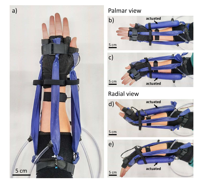
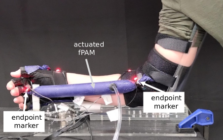
In this paper, we present a novel soft wrist exosuit actuated by fabric pneumatic artificial muscles (Fig. 1). Our research focuses on assessing the capability of this lightweight, low-cost, and soft actuator within the context of an exosuit prototype. We aim to determine its effectiveness in generating sufficient torque similar to biological joints and in moving the wrist along a large range of motion in the two degrees of freedom of flexion/extension and ulnar/radial deviation. Also, the device is designed with a mechanical stop that prevents the wrist from going beyond the natural joint limits, making the device inherently safe. This stop is based on the fact that the fPAM actuator cannot exert force beyond its maximum contraction ratio and has an inherent limit in stretchability. These two properties, however, impose limitations on the exosuit-assisted range of motion and on the applied torque at wrist angles where the actuator is close to its fully contracted state.
We present a model-based methodology for the selection of parameters governing the design of fPAMs and their positioning on the body aiming to attain a prescribed torque profile that spans the entire range of motion of the wrist. Our optimization process selects placement parameters with the objective of closely approximating the peak biological flexion torques exhibited by the human wrist. We also provide experimental validation of the modeled torques throughout the range of wrist flexion/extension, and we compare the biological and exosuit-assisted range of motion in both flexion/extension and ulnar/radial deviation. Finally, we present a demonstration of the device actively controlled to move the wrist to a desired flexion/extension angle with a pair of antagonistic artificial muscles and to follow a desired two-degree-of-freedom trajectory by coordinating the movement of both pairs of actuators.
II Design and Fabrication
This section discusses the considerations which led to the current design of the exosuit. After an overview of the design concept, we introduce the exosuit prototype in detail. We describe the wearable elements, including the mounting methods to connect fPAMs, as well as the off-board components, including the electronics and the parts of the pneumatic system.
II-A Design Overview
The main goals of our study are to design a lightweight, wearable, soft device to assist the mobility of the human wrist and to explore the capabilities of fPAMs for actuating soft exosuits. While there are several criteria for designing wearable devices, such as safety, ergonomics, autonomy, and cost [5], here, we focus on creating the largest possible range of wrist motion and torque application. Because of the properties of the actuator, two other design criteria, safety and low cost of the wearable parts, are automatically satisfied.
Our wrist exosuit design (Fig. 1) consists of four pneumatic artificial muscles arranged radially around the wrist at 90∘ to each other. When each muscle is contracted upon applying positive pressure, it promotes one of the following wrist movements: flexion, extension, ulnar deviation, and radial deviation of the wrist. Due to the described placement of the fPAMs, there are antagonistic pairs of actuators in the sagittal and frontal planes. This actuator configuration allows movement limits to be an inherent part of the physical system. When one muscle inflates, the initially minimal resting force of the opposite side muscle increases while the muscle is stretched. The antagonist muscle acts as a hard stop when it reaches its maximum length change. Also, the limited contraction ratio of the agonist fPAM stops the movement at a given joint angle.
II-B Exosuit Prototype
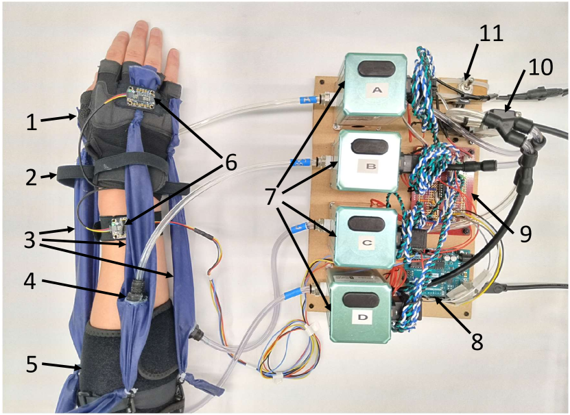
The exosuit prototype is shown in Figs. 2 and 3. The main wearable components are a fabric elbow brace, a fabric glove, the fPAMs, and two inertial measurement units (IMUs) (BNO055, Adafruit) having a total weight of 160 g. One IMU is placed on the dorsal side of the hand, and another is attached to the dorsal side of the forearm in the same orientation when the wrist is straight (Fig. 2). The relative orientation of the IMU sensors provides two-degree-of-freedom wrist angle information for the system.
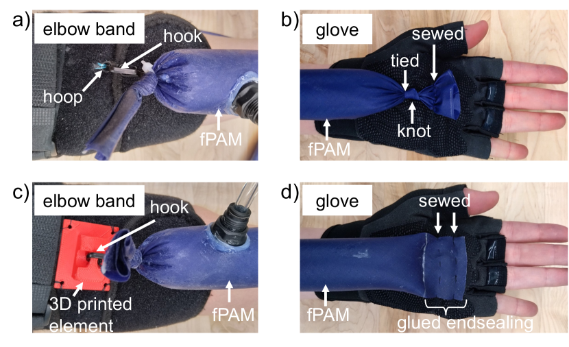
We made the fPAMs out of silicone-coated ripstop nylon fabric (30 Denier Double Wall Ripstop Nylon Silicone Coated Both Sides, Rockywoods) based on the fabrication steps described in [18] with the ends of most muscles sealed by tying a knot and using glue (Sil-Poxy, Smooth-On) to prevent its sliding. We added push-to-connect pneumatic fittings reinforced with glue on the sides of the muscles to attach the air tubes. One end of each fPAM is connected to a metal hook and attached to a ring sewed to the elbow brace (Fig. 3(a)), while the other end is sewed to the glove (Fig. 3(b)). This enables the muscles to be stretched tighter than their deflated resting length by attaching them to the elbow band after the glove and the band are put on. Each fPAM is routed through a restricting elastic band which is attached to the glove to ensure that the fPAMs can not slide off the surface of the wrist when they wrap around it.
An alternative method to connect the end of the fPAM to the elbow band is shown in Fig. 3(c). In this case, a 3D-printed plastic piece is sewed to the band and serves as the structure to which the metal hook can be attached. Incorporating this rigid structure allows us to place the attachment point further away from the body but adds more non-fabric components. An alternative method for attaching the muscle to the glove is to seal the end of the fPAM by gluing the fabric together and then sewing it to the glove (Fig. 3(d)). This method increases the low profile nature of the design, but it was not used here, as it proved to be less durable, and the position of the attachment point was more difficult to define.
Besides the wearable part, the exosuit consists of off-board components. The fPAMs are connected to closed-loop pressure regulators (QB3, Proportion-Air) through air tubes with a 6.35 mm outer diameter. The regulators can maintain the pressure level between 0 and 137 kPa depending on the input voltage. In the current configuration, a pressurized air source of 200 kPa connected to the regulators through a solenoid valve is used to supply air to the system. An Arduino Uno control board is used to set the desired pressure level based on the angle of the wrist obtained by the IMUs using the control scheme described in Section VI. The control signal from the microcontroller goes through a signal conditioning circuit consisting of a low-pass filter and a buffer to set the input voltage to the pressure regulators. The board is supplied by a 15 V DC power source, and it is equipped with a safety switch that controls the solenoid valve to cut off the air supplied to the system.
III Modeling
In this section, we introduce a planar geometric model of our exosuit design that will be used to calculate the torque applied by an fPAM to the wrist. We propose two torque equations, one describing the torque when the fPAM is running in a straight line between the mounting points, and a second describing the torque when the fPAM partially wraps around the wrist (e.g., the flexor fPAM in the fully extended wrist position).
III-A fPAM force modeling
The force that an fPAM can apply at a given level of contraction can be calculated from [18] and is described by Eqn. 1.
| (1) | ||||
| where | ||||
The produced force () of an fPAM with a given length () depends on the internal pressure (), the contraction ratio () defined as the change in length over the original, fully stretched length of the fPAM , the fully stretched fiber orientation of the fabric (), the fully stretched radius of the fPAM (), the fabric thickness (), and the elastic modulus of the fabric (). The equation is composed of two components added together. The first, pressure-dependent component is the ideal McKibben muscle model [20], which represents the contraction force of a pressurized cylinder that reduces its length while its radius increases with the restriction of an unstretchable outer mesh. The second, pressure-independent component models the force that the stretched fabric applies as linear elasticity. The intercept point is denoted by , which corresponds to the contraction ratio where the deflated fPAM starts to apply elastic force when it is stretched. We assign zero elastic force for contraction ratios larger than .
The fPAM reaches its fully contracted length when the applied force becomes zero. Our tensile testing measurements (Section V-A) show that the maximum contraction ratio () varies with pressure, therefore it is important to incorporate this variable into the force equation. To achieve this, we calculate the initial fiber orientation for each pressure by Eqn. 2 [18], so that the force equation implicitly includes .
| (2) |
Tis formula is derived by substituting and into Eqn. 1. At this value of , the elastic, pressure-independent component is zero, and the equation can be rearranged to solve for .
III-B Exosuit torque model
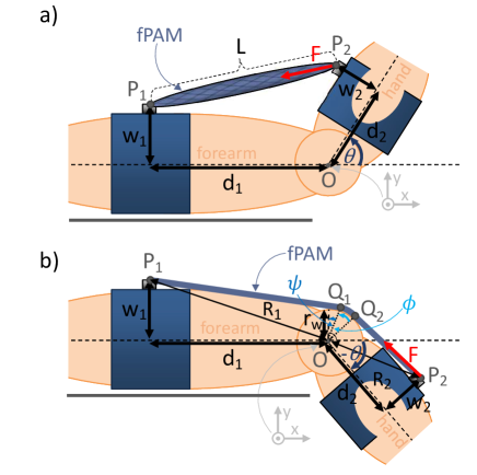
To approximate how much torque a single fPAM can apply to the wrist, we need to know the position of its two endpoints, relative to the center of rotation of the wrist. We used the two-dimensional geometric model (similar to the model used for the cable-driven exosuit in [10]) shown in Fig. 4 to calculate the torque that an actuator producing a given force () can apply to the wrist at a given wrist angle . We use slightly different models for the torque computation at wrist angles where the actuator does not wrap around the wrist (Fig. 4 (a)) and where it does wrap around the wrist (Fig. 4 (b)). In both models, we make the following assumptions regarding the wrist kinematics and fPAM placement. The forearm and the hand are modeled as rigid links connected by a revolute joint. The two mounting points and the center lines of the two links are in the plane perpendicular to the axis of rotation. The axis intersects the plane at point , which is defined as the center of rotation. In this plane, represents the projected length of the vector from the mounting point on the forearm () to the center of rotation () onto the center line of the forearm, and represents the shortest distance between the center line of the forearm and the mounting site on the forearm. The and distances denote the analogous placement parameters for the mounting point on the hand (). The joint angle describing the orientation of the hand relative to the forearm is drawn in the positive direction on Fig. 4(a) given that the reference coordinate frame is defined with the axis aligned with the axis of rotation and the axis parallel to the forearm, pointing in the direction of the hand. The figure illustrates flexion/extension movement, however, this model can be generalized to describe wrist rotation around another rotational axis of the wrist.
III-B1 Straight line model
In the case where the actuator does not wrap around the wrist (Fig. 4(a)), the modeled torque is given by Eqn. 3. This torque is calculated by the cross product between the vector from to and the vector along the fPAM in the direction from to with magnitude . is the current length of the actuator, which is calculated as the Euclidean distance between the mounting points and .
| (3) | ||||
| where | ||||
III-B2 Partially wrapped model
In the case when the actuator partially wraps around the wrist (Fig. 4(b)), an extended geometric model with an approximated radius of curvature of the wrist can be used to calculate the torque. The wrist is assumed to have a circular surface with a constant radius (), which defines the point where the fPAM first touches the wrist () and the length of the segment where the fPAM is in contact with the wrist (from to the last point of wrapping ()). The angle is defined as the angle between the axis and the vector from to , and the angle corresponds to the arc segment where the wrapping occurs (i.e., between and ). The angle is calculated by finding the position of using Thales’s theorem to construct the tangent from to the wrist circle. Also, the and parameters are assigned to denote the distances between the mounting points and the center of rotation. This allows us to define a closed-form expression for as given in Eqn. 4.
| (4) | ||||
| where | ||||
To calculate the torque, first, we need to consider the change in the length of the fPAM. We formulated a new equation (Eqn. 5), where the overall length of the muscle () during wrist wrapping is the sum of the distance between and , the arc length between the wrapping points and and the distance between and . The derived equation for the muscle length will be used to calculate the ideal fully stretched length of each fPAM by substituting the maximum wrist angle in the direction that causes wrapping into the equation.
| (5) |
Once we know the length of the fPAM, the magnitude of the fPAM force () at a given pressure can be computed using Eqn. 1. Compared to calculating the Euclidean distance between the endpoints, as in the case when the actuator does not wrap around the wrist, the length is increased, and therefore the magnitude of the force will be larger. The force will point in the direction from to . Similarly to the previous torque equation, the torque () during wrist wrapping is computed as the cross product of the vector from to and the force vector (Eqn. 6).
| (6) | ||||
| where | ||||
The transition between the straight-line and wrapping model occurs when the fPAM touches the surface of the wrist while the joint extends. For the 2D geometric model, this occurs when the line along the two mounting points changes from being disjoint to becoming tangent to the circle representing the wrist. To decide which model to use for a given joint angle, we examine the number of intersection points between the line along and (assuming the general form of ) and the wrist circle () by solving the system of equations for the and coordinates of the shared points. This leads to a quadratic equation in either or , therefore the discriminant of the quadratic formula () (Eqn. 7) can be used to determine the number of solutions.
| (7) |
The transition between the straight line to the wrapping model happens, when there is one intersection point ().
IV Design Optimization
In this section, we examine how can we design the exosuit to have the strength to fully assist the movement of the human wrist. This corresponds to the challenge of finding the parameters of the exosuit such that it can apply as high torque as the maximum biological torque in any wrist configuration. To solve this task, we conducted a parameter optimization to fit the modeled torque to biological reference data. First, we discuss how the reference biological torque data was selected, then we describe the decision process behind selecting the set of parameters to optimize, and finally, we present the parameter optimization results using our torque model.
IV-A Reference biological torque
Published peak torque data of the biological wrist can be found in the literature [21, 22]. These biomechanical studies state that the measured torque depends on multiple factors including the wrist posture. The effect of wrist posture was investigated by measuring the peak wrist torques in various wrist configurations [22]. The maximum torque values for wrist flexion, extension, radial deviation, and ulnar deviation were reported, along with a range of motion data in these directions. The results in [22] showed that the maximum torques in ulnar and radial deviation (7.14 Nm and 6.33 Nm, respectively) are higher than in flexion and extension (4.42 Nm and 3.41 Nm, respectively) but the range of motion is significantly smaller ( of the flexion/extension range).
Based on the force-contraction ratio relationship of the fPAM [18], this actuator can provide high forces when the contraction ratio is close to zero, but the force approximately linearly decreases to zero as the muscle contracts. Therefore, we expect that it is more difficult for the exosuit to match the biological torques when the torque values follow a uniform distribution over a large joint angle range. We chose the flexion torque over the flexion/extension range to be the reference data, as this torque profile is the closest to the previously described criteria, and thus it is the most challenging for the exosuit to reach. Peak biological wrist force during flexion of the human wrist in the 90∘ extension to 90∘ flexion joint range (with an increment of 15∘) was reported in [21], but the data suggests that the range of motion is larger than the range reported in other sources [6, 22], and it shows that the torque increases as the wrist approaches the fully flexed state, which is not aligned with our observations.
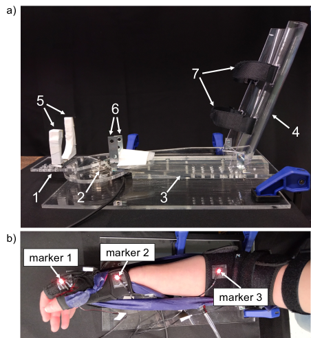
Instead of using data from the literature, we conducted a torque measurement on a single subject using the setup in Fig. 5, which is made of acrylic sheet and tube elements. The hand plate (component 1 in Fig. 5(a)) is connected to the torque sensor (Mini 45, ATI) (component 2), which has a circular plate on the top side and which is fixed to the base plate on the bottom side. The hand plate is directly attached to the circular plate such that the orientation of the hand plate can be changed using screws to fix the angle of the wrist in a desired position between 90∘ extension and 90∘ flexion with an increment of 22.5∘. The forearm plate (component 3) reaches over the circular plate to provide support for the forearm, but it is only attached to the base plate. At the other end of the forearm plate, a tilted half cylinder (component 4) connects to it to secure the position of the upper arm. Additional support structures, i.e., brackets and hook-and-loop tapes (components 5, 6, and 7), prevent the horizontal displacement of the hand, forearm, and upper arm.
Throughout the torque measurement, the wrist angle was monitored by recording the position of three motion capture markers (Impulse X2E, PhaseSpace) on the exosuit. The locations of the markers were defined based on the marker placement in [23] adding some changes due to the measurement setup limiting the available surfaces on the radial side of the arm. The marker at the hand is on the head of the second metacarpal, the marker at the wrist is on the styloid process of the radius, and the marker at the elbow is approximately halfway between the medial and lateral epicondyle of the humerus. Fig. 5(b) illustrates the markers placed on the hand (marker 1), the wrist (marker 2), and the forearm (marker 3). Because the vertical positions of the markers are not the same, the vectors between the markers were projected into the horizontal plane when the angle between them was calculated.
The peak voluntary flexion torque was measured three times (while the fPAMs were not actuated) varying the angle of the hand plate from 67.5∘ extension to 90∘ flexion in steps of 22.5∘.The average biological peak torque is shown in Fig. 6, along with the parameter optimization results described in the next subsection. It is important to note that the measured reference data is not generalized for multiple users, however, the results provide the torque profile of a healthy individual capable of performing activities of daily living. Moving forward, the findings of the paper discuss the results of this case study.
IV-B Parameter optimization
The goal of the parameter optimization is to find the parameters that allow the exosuit to achieve at least as high torque as the biological reference torque at all wrist angles. The collected average biological peak torque data described in the previous section was used for the optimization, with the number of data samples increased from 8 to 140 using “spline” interpolation in MATLAB (continuous grey line in Fig. 6). This made the optimization more independent of the specific angles chosen for the measurement points. We formulated an objective function as the sum of the positive differences between the biological reference torque and the modeled exosuit torque across the full range of joint angles. By minimizing this objective function, a mismatch between the model and reference data is penalized when the modeled exosuit torque is lower than the reference torque.
The exosuit parameters can be divided into two groups. The first group includes the fPAM parameters, which describe the actuator itself as in the modeling equations: the fully stretched radius () and length (), and the internal pressure (). The second group includes the placement parameters, which describe where the fPAMs are attached to the glove and elbow band (, , , and in Fig. 4).
In the first group, the fully stretched radius and the initial length depend on the fabrication process of the fPAM, and the applied pressure can be changed through the operation of the exosuit. Because the torque is proportional to the magnitude of the fPAM force, the force should be maximized for the purpose of optimization. The pressure and the square of the radius are both proportional to the magnitude of the ideal, pressure-dependent force, and the radius is proportional to the elastic force (Eqn. 1), so these parameters should be fixed at their highest value. The highest achievable pressure based on our current physical system is 137 kPa, which corresponds to the maximum output pressure of the pressure regulators. For this optimization, we consider the maximal contraction ratio () to be 0.28, as that corresponds to 137 kPa in [18]. We chose to set the fully stretched radius to 1.23 cm, which corresponds to the widest fPAM (with approximately 5 cm diameter when unstretched and uninflated) that we fabricated and subjectively considered to be low profile in the exosuit. For different design considerations and system properties (e.g., different pressure regulators), the choice of these parameter values is restricted only by the inverse proportional relationship between the maximum pressure and the fully stretched radius [18]. Similarly, the force magnitude is higher if the muscle is less contracted, therefore the initial, fully stretched length of the fPAM should be the shortest length that still allows the user to reach the full range of motion in the direction that stretches the muscle. We computed the initial length using Eqn. 5 with the maximal extension angle to match these criteria. For this optimization, we defined the maximal extension angle as 65.4∘, which corresponds to the largest extension angle where we measured reference peak biological torque. Because we used one specific type of silicone-coated ripstop nylon fabric, the fabric thickness () and the elastic modulus of the fabric () are constant parameters. The reported thickness of the fabric by the manufacturer is 0.08 mm, and the value that we used for elastic modulus is 9.06 MPa based on our discussion with the authors of [18].
The placement parameters determine the moment arm and the required actuator length change, as well as the direction of the actuator force, which changes throughout the range of motion. Therefore, it is not straightforward how they influence the exosuit torque. For example, minimizing seems to be a good choice to maximize torque, because moving the mounting point closer to the wrist center of rotation leads to a smaller required actuator length change, allowing the actuator to operate closer to its maximum force, but the moment arm will simultaneously be reduced, which decreases the torque. Therefore, we conducted a design optimization on the four placement parameters. We defined upper and lower bounds on each parameter based on the dimensions of the arm of the current user and our capability to make a firm attachment point on the glove and the elbow brace. For and , the lower bounds ensure that we can still place a short fPAM across the wrist by keeping a small distance from the center of rotation both on the forearm and the hand. The upper bounds are based on the fact that the lengths of the hand and forearm limit how far away the fPAM can be placed from the wrist. For and , the lower bounds are based on the smallest width measured on the hand and forearm, and the upper bounds are based on increasing these distances by adding an elevating structural component to the exosuit (Fig. 3(c)). Our choices of parameter bounds are shown in Table I.
| Lower bound [cm] | 2.00 | 3.50 | 1.50 | 1.50 |
| Upper bound [cm] | 22.00 | 5.00 | 9.00 | 3.50 |
| Resolution for initial guesses [cm] | 2.00 | 0.50 | 0.50 | 0.50 |
| Optimized values [cm] | 22.00 | 3.50 | 9.00 | 1.50 |
The last parameter that appears in the torque equations is the radius of the wrist. This parameter is independent of the exosuit configuration. The radius was computed as half of the measured width of the human wrist in the sagittal plane, which is 2 cm for the user in this study.
To find the optimal values of these parameters, first, we conducted an exhaustive search on the discretized parameter space with 100 points for and and 50 points for and . Then, we used another method for the optimization to reduce the running time, which was based on using the modified version of the built-in function fminsearch in the MATLAB Optimization Toolbox that allows the definition of upper and lower bounds of the parameters. The running time of a single cycle of the algorithm is on average 0.9 seconds. Because it is not guaranteed to converge to the global minimum, we ran the optimization for a set of initial guesses and chose the resulting values that minimized the objective function. The set of initial guesses contained points of the discretized parameter space with the resolution presented in Table I. The two algorithms gave the same set of parameters, but the running time was significantly shorter, 24 minutes on average for the second method compared to 4 hours and 44 minutes for the first method, therefore it proved to be more efficient for the parameter optimization.
The torque with the optimized parameter values is plotted in Fig. 6 across the flexion/extension wrist angles.
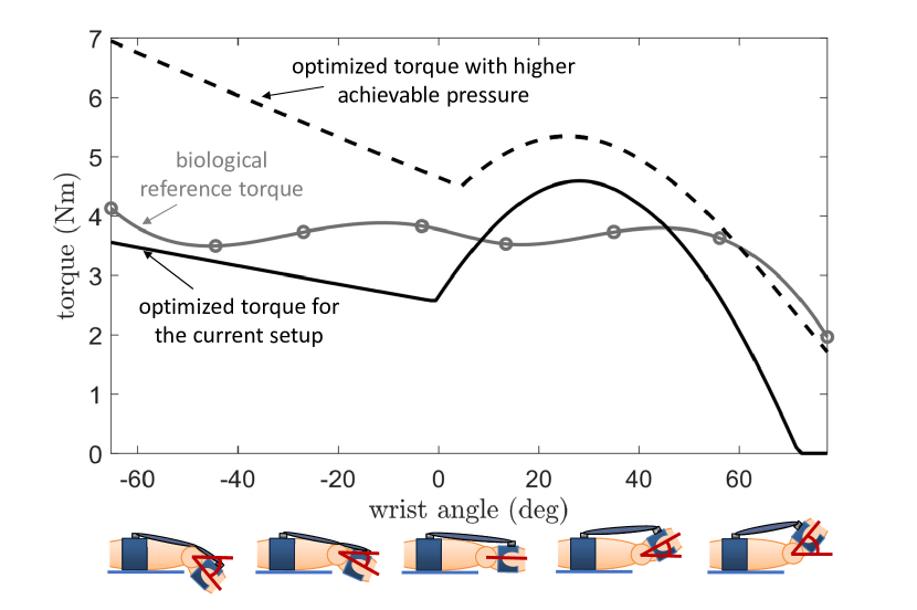
The optimization results show that the optimized exosuit torque (black curve in Fig. 6) is smaller than the biological peak torque (grey curve) for all wrist extension angles, with a value close to the reference torque at full extension but linearly decreasing until reaching 1∘. However, the torque increases at the early stage of wrist flexion and becomes higher than the reference torque for a set of flexion angles starting from 9∘. The exosuit torque becomes lower than the biological peak torque at 46∘ and continues decreasing until it reaches zero at 72∘. When the wrist moves from full extension to 1∘ of extension (close to the neutral position), the model describing the fPAM wrapping around the wrist defines the torque (Eqn. 6). In this range, the moment arm is constant, but the force and thus the torque decreases as the muscle length shortens compared to the fully stretched length. When the wrist is rotated from 1∘ of extension towards full flexion (with torque described by Eqn. 3), the muscle runs in a straight line between the mounting points, and its length monotonically decreases. Although initially the torque increases due to the sudden increase in the moment arm, the torque eventually approaches zero as the moment arm gradually stops rising and the fPAM continues to produce smaller forces. This result indicates that, given the set of constraints we have placed on our design, an fPAM-based exosuit for this specific user cannot reach the same peak torque over the whole range of movement as the human wrist. Note, however, that the typical functional range of human wrist motion (35∘ of flexion/extension [6]) is smaller than the full joint range, and on this smaller range, the exosuit should reach close to the peak biological torque.
Besides the parameter optimization for our current setup, we ran a second optimization to predict the exosuit torques for a system that can provide twice as high pressure (274 kPa) as the current system (137 kPa). This pressure is below the 448 kPa burst pressure of the fPAM with the implemented fully stretched radius of 1.23 cm, which was calculated as described in [18]. The optimal placement parameters remained the same compared to the previous optimization, except was decreased to 3.53 cm, and the predicted torque (dashed black curve in Fig. 6) is higher than or very close to the biological torque over the full flexion/extension range.
IV-C Parameter perturbation
In addition to analyzing the modeled torque with the optimized parameter values, we added perturbations to the optimized parameter set for our current setup to examine how the change in individual parameters influences the modeled torque of the wrist exosuit. We considered parameters outside of the parameter bounds used for the optimization so as to understand the effect of considering new design approaches to change the parameter bounds. This exploration also helps us understand how the physical prototype might behave if its parameters are not exactly as expected or vary during operation.
Fig. 7(a) presents the modeled torques when actuator design parameters ( and ) are perturbed by 0.5 cm and 69 kPa, and the initial length () is perturbed by 1 cm. Here the perturbation means that one parameter value is increased or decreased while the other parameters are unchanged. The fPAM force is proportional to the internal pressure and the square of the radius, so increasing these quantities provides the desired torque for higher joint angles, but the range of motion is not affected by the perturbation of these parameters. However, when the muscle’s initial length gets smaller, the modeled torque reaches zero at a larger flexion angle. This means that the upper limit of the wrist flexion angles, where the biological peak torque is reached, can be increased, but simultaneously, the range of possible extension angles is decreased. Therefore, the range of motion in the flexion/extension plane remains limited, but it can be shifted in favor of the flexion or the extension direction. When is increased, the muscle will be slack at full extension, thus the overall torque magnitude and the maximum flexion angle will be reduced. This can occur on the exosuit when the fPAM is not stretched enough when it is put on.
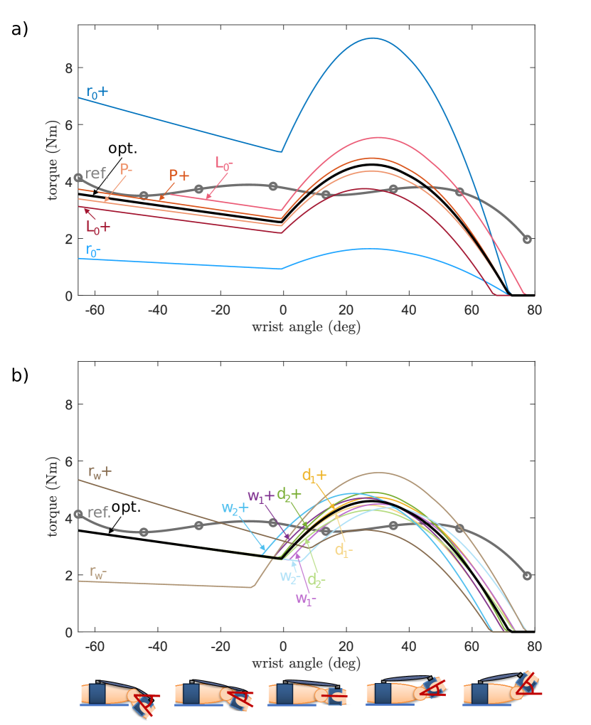
Fig. 7(b) shows the modeled torques when , , , , and are changed by 1 cm and the initial length of the muscle is recalculated accordingly. These perturbations demonstrate how the exosuit torque changes when the positions of the mounting points differ from the optimal placement. Some perturbations correspond to scenarios when the parameters exceed the defined bounds. This indicates how the optimized torque profile would change for users with different arm dimensions. When is increased, the lever arm does not change significantly, but the fPAM becomes longer, which results in a larger capability for absolute length change of the muscle and thus increased torque overall joint angles. For , it depends on the joint angle whether the increase or the decrease of this parameter value results in a higher torque. Moving towards the fully flexed wrist position, increasing leads to first increased and then decreased torque, and decreasing leads to first decreased and then increased torque. This behavior is based on the combined effect of the change of the lever arm and the change of the fPAM force given the formulated muscle length. The perturbation of and follows a similar trend to the perturbation of , but changing makes only a small torque magnitude change, while has a more significant influence on the torque, especially affecting the wrist angle where the torque reaches zero. Additionally, the perturbation of closely corresponds to the distance between the fPAM and the wrist, so it decreases delays, and its increase brings forward, the unwrapping towards wrist flexion. The radius of the wrist () is the only placement parameter that changes the moment arm during wrapping. The perturbation of changes the slope of the torque when the wrapping model applies, the wrist position where the transition to the straight-line model occurs, and the range of motion and the torque magnitude over the wrist flexion angles.
V Model Validation and Experimental Results
As the modeled exosuit torque is based on a two-dimensional geometric model with fixed parameters, it is not guaranteed that the behavior of the soft physical system can be accurately predicted by the described equations. In this section, we describe the procedure and results of the measurement of the torque of the physical exosuit, as well as the process of identifying model parameters. We propose adjustments to the model that increase its accuracy. We also present the results of a measurement to compare the biological and exosuit-actuated range of motion of the human wrist.
V-A Measurement of the fPAM force
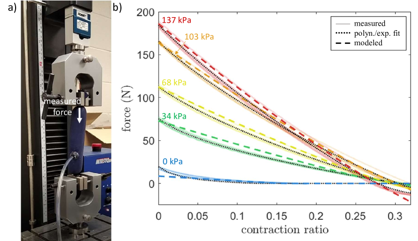
Before attaching the flexor fPAM on the exosuit, we conducted a tensile testing measurement (Fig. 8) to identify the parameters of the modeled force of the actuator. During the measurement process, the fPAM was stretched from its initial, fully contracted state (measured on the inflated fPAM at a given pressure when the force readings approached -10 N) to zero contraction (measured on the deflated fPAM when the applied load was 230 N as in [18]) and then it was returned to its initial state. The linear force of the fPAM was measured by a load cell (SM-1000-961, ADMET) for three cycles of length change. The measurement was repeated for five pressure levels (0 kPa, 34 kPa, 68 kPa, 103 kPa, and 137 kPa). The test setup is shown in Fig. 8(a), and the measurement data is shown in Fig. 8(b).
For each nonzero pressure level, the smoothed and averaged force-contraction ratio plots were approximated by an 8th-order polynomial so that we could sample points at arbitrary contraction ratios. The same polynomial approximation does not work well for the zero-pressure elastic force, which converges to zero when the contraction ratio increases, therefore a piecewise function consisting of an exponential and a constant zero function was used for approximating the fPAM force at zero pressure. The initial length and radius of the fully stretched but uninflated fPAM were measured, and the maximum contraction ratio was derived from the zero crossing of each force curve for each different pressure level. Still, an adjustment of and was required to match the modeled force to the measured data. For the fPAM forces which correspond to nonzero pressure, this was achieved by running an exhaustive search over the discretized parameter space to minimize the difference between the measured and modeled ideal force in the neighborhood of the measured values of these parameters. For the zero pressure elastic force, we used the exhaustive search to get an optimal value for assuming that equals the average of its previously calculated values. Table II contains the derived fPAM parameters with denoted as the value at zero pressure. The angle of the fiber orientation was calculated based on the derived maximum contraction ratio as described in the model of the fPAM (Eqn. 2). The modeled force based on Eqn. 1 is plotted in Fig. 8(b) using the calculated parameter values.
| [kPa] | 0 | 34 | 68 | 103 | 137 |
|---|---|---|---|---|---|
| [cm] (measured) | 34.0 | 34.0 | 34.0 | 34.0 | 34.0 |
| [cm] (measured) | 1.02 | 1.02 | 1.02 | 1.02 | 1.02 |
| [cm] (calculated) | 1.23 | 1.27 | 1.22 | 1.19 | 1.26 |
| (calculated) | 0.153 | 0.303 | 0.296 | 0.301 | 0.277 |
V-B Torque applied by the exosuit
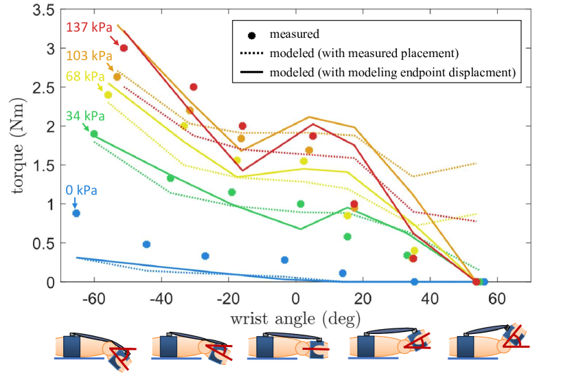
We used a torque sensor (Mini 45, ATI) to measure the torques applied by the flexor muscle of the exosuit to the relaxed wrist over the range of wrist angles from 67.5∘ to 90∘ with an increment of 22.5∘ on the same experimental setup which was used for the measurement of biological peak torques previously presented (Fig. 5). Similarly to that experiment, the measurement was repeated for five pressure levels (0 kPa, 34 kPa, 68 kPa, 103 kPa, and 137 kPa) three times at each wrist angle. The arm of the user was attached to the setup as illustrated in Fig. 9. The attachment point of the fPAM on the hand was placed close to the fingers to leave space for the brackets in the middle of the palm to brace the hand. The other mounting point was placed on the forearm as close to the elbow as possible. As the elbow band and glove that the fPAM connects to are both made of fabric (and the surface of the human arm is soft as well), the positions of the mounting points at the ends of the fPAM change when the muscle is inflated or stretched. For this reason, the positions of the attachment points need to be monitored to accurately model the torque. To track the positions of the endpoints relative to the human arm, motion capture markers were placed on the radial side of the exosuit to measure the current wrist angle (as before), and also on the palmar side of the exosuit right over the knot at the end of the fPAM as shown in Fig. 9. The placement parameters corresponding to the two-dimensional geometric wrist model were derived from the horizontal components of the marker coordinates. The parameters from Table II were used to model the fPAM force, but the initial length of the fPAM was reduced to 32.0 cm to make the actuator more stretched at full wrist flexion given the actual placement. The radius of the wrist () was determined by running an exhaustive search over a range of 1 cm to 7 cm with a resolution of 0.01 cm to minimize the sum of the RMS error between the measured and modeled torques for the two models over all data points.
Fig. 10 shows the measured and modeled torque values based on actuating the flexor fPAM over the defined flexion/extension range. The dots correspond to the average measured exosuit torques at each wrist angle, where the colors indicate the applied pressure going from 0 kPa (blue) to 137 kPa (red). We used two approaches to derive the placement parameters for the exosuit torque model. The first method (dashed lines) used the actuator endpoint position data from the motion capture system at each measurement point. The second method (solid lines) modified the model to predict the exosuit torque without directly using real-time data from the motion capture system.
For the second method, the placement parameters were fixed to be equal to the measured parameters with the actuator deflated and at zero wrist angle (Table III). To model the displacement of the actuator endpoints relative to their initial position on the body, a model in the form of Eqn. 8 was added, which includes the effect of the fabric stretching of the elbow band and the glove, and the translation of the soft tissue of the arm.
| (8) |
The indices differentiate the sites of the actuator endpoints, where corresponds to the forearm and corresponds to the hand. The force () equals the magnitude of the force applied by the fPAM at the endpoints. The denotes the displacement of each endpoint in the direction of the force. Using the endpoint position data, we calculated the force and displacement at each measurement point. The stretching coefficients were computed at each measurement point using Eqn. 8, and these values were averaged to derive a single value for each coefficient (Table III).
As shown in Fig. 10, the second model approximates the torque better when the joint angle approaches the fully flexed position. The mean absolute error (MAE) of the second model’s overall measurement points is 0.279 Nm, which is 26.1% of the average magnitude of the measured torques, while the MAE of the first model is 0.374 Nm, which is 34.9% of the average torque magnitude.
| [cm] | [cm] | [cm] | [cm] | [cm] | [cm] | [] | [] |
|---|---|---|---|---|---|---|---|
| 19.47 | 4.93 | 8.30 | 3.38 | 32.00 | 3.99 | 43.36 | 1097.50 |
V-C Range of motion
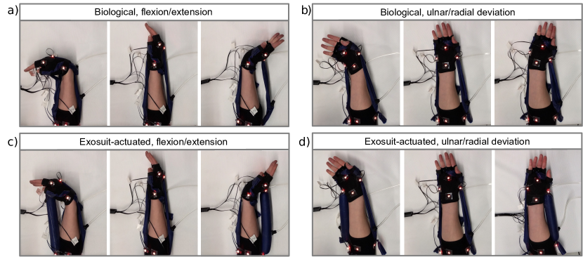
We also conducted a measurement to compare the active biological and the exosuit-actuated range of motion of the human wrist. Motion capture markers were placed on the exosuit similarly as for the torque measurement (Fig. 9), but this time markers were placed on both the radial and the palmar side of the arm to collect angle data along two different planes. The endpoints of the actuated muscle were also tracked. The extensor muscle was attached to the hand just below the head of the third metacarpophalangeal joint. The radial deviation muscle was placed close to the base of the first metacarpal (the base of the thumb) and the ulnar deviation muscle was mounted symmetrically to the opposite side of the hand. The other mounting points for all fPAMs were placed on the forearm as close to the elbow as possible. The measurement process consisted of two parts. First, the exosuit-actuated wrist range was measured when the arm of the user was relaxed and the exosuit was actuated by applying 137 kPa pressure to the corresponding fPAM to passively move the human wrist to maximum flexion/extension (Fig. 11(a)) and ulnar/radial deviation (Fig. 11(b)) while the forearm was placed on the table. Then, the same measurement was repeated when the user of the exosuit voluntarily moved the wrist and the fPAMs on the exosuit were not actuated (Fig. 11(c) and (d)). Table IV contains the average and the standard deviation of three range of motion measurements for both the exosuit-actuated and the voluntarily moved wrist.
To derive the modeled range of motion, the same measurement was repeated once with tracking the endpoints of the actuated muscles at the joint limit. The torque was estimated form 0∘ to 90∘ along the four movement directions using our first torque model with placement parameters derived by the same method as for the torque measurement. We assumed that the fPAM parameters and are the same as for the measured flexor fPAM at 137 kPa for all the muscles and we measured the fully stretched length for all fPAMs separately. The modeled joint limits were defined as the wrist angle where the modeled torque reached zero. The model error was computed by subtracting the measured exosuit angle limits from the modeled angle limits. The modeled limits were higher in all cases and so the computed error values are positive (Table IV).
| flexion | extension | ulnar dev. | radial dev. | |
|---|---|---|---|---|
| exosuit | 44.5∘ (STD 7.5∘) | 38.7∘ (STD 5.2∘) | 26.8∘ (STD 3.4∘) | 15.9∘ (STD 3.3∘) |
| biological | 80.9∘ (STD 6.7∘) | 56.0∘ (STD 6.8∘) | 39.1∘ (STD 1.3∘) | 23.2∘ (STD 2.3∘) |
| model error | 5.3∘ | 20.9∘ | 16.1∘ | 14.0∘ |
VI Control and Demonstration
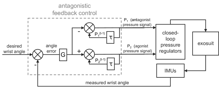
To demonstrate how the prototype of the wrist exosuit functions to move the human wrist, we implemented a control algorithm to automatically position the wrist at a desired joint configuration (Fig. 12). We applied feedback control, as it is easy to implement and only requires input information about the wrist angle, which is measured by the two IMUs on the exosuit. Although this also limits the precision of the control, we successfully used the feedback algorithm for the two trajectory tracking tasks described in this section.
VI-A Wrist angle measurement
Our control system (Fig. 12) is based on the error between the desired and actual wrist angle. The wrist configuration consists of two physical angles that independently represent the flexion/extension angle and the ulnar/radial deviation angle, and these angles can be regulated by two independent controllers. First, we calculated these physical angles from the measurements of two IMUs. One IMU is placed on the dorsal side of the forearm and the second one is placed on the dorsal side of the hand. The wrist orientation is given by the relative orientation of the two IMUs. The quaternion representing this relative orientation (q) is computed based on the formula [24] expressing successive rotations in quaternions. This formula is presented in Eqn. 9 with notation specific to our application.
| (9) |
In the formula, and [ ]T are the scalar and the vector components of q. The same notation is used for the components of the q{f} and q{h} quaternions, which represent the orientation of the IMUs on the forearm and the hand, respectively. After this conversion, the wrist orientation is expressed in the right-handed coordinate frame of the forearm IMU, which is positioned such that the axis is aligned with the forearm and points towards the hand, and the axis lies in the coronal plane and points in the ulnar direction. Using Rodriguez’s formula, the relative orientation is converted into spherical coordinates using Eqn. 10 with defined as the polar angle measured from the polar axis and as the azimuthal angle measured from the axis. Then, from the angles of spherical coordinates, the physical angles are derived using Eqn. 11.
| (10) | ||||
| (11) | ||||
These physical angles correspond to the wrist angle in the flexion/extension () and ulnar and radial deviation () directions.
VI-B Control system
Based on the measured actual wrist angle and the desired wrist angle, the wrist angle error is used to change the pressure of the antagonistic muscles that control each physical angle. To produce antagonistic coordination, the error, scaled by a gain, is added to the current pressure of the agonist muscle that moves the wrist closer to the desired angle and subtracted from the current pressure of the antagonist muscle resisting the movement. We set the value of the gain to kPa/deg (manually tuned based on observing the performance of the controller), which helps to convert the error in degrees to a small change of pressure in kPa at each time step through the control loop, which in our implementation had a timestep of 0.014 s. The pressure is then capped to restrict its value to the assigned operating range from 0 kPa to 68 kPa. The upper limit was set to approximately the smallest pressure value that was not exceeded in any of the fPAMs while completing the defined tasks. Co-contraction of the two muscles causes increased stiffness. The initial stiffness depends on the initial pressures, which were set to 13.8 kPa for all muscles, but the stiffness was not directly regulated during operation. The stiffness, however, can increase during operation when, for example, the wrist movement is restricted and the pressure builds up in one muscle. To be able to decrease this built-up stiffness, we included an additional condition that the pressure of the resisting fPAM should decrease twice as fast if its current pressure exceeds a given threshold. This threshold was set as 13.8 kPa based on observing the operating pressures with simple antagonistic feedback. The desired pressure levels were converted to a voltage signal and sent to the closed-loop pressure regulators connected to the corresponding fPAMs.
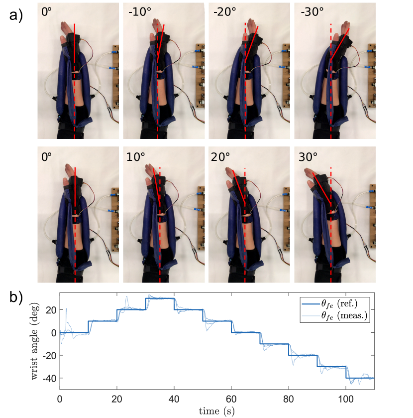
VI-C Planar angle tracking
As a first demonstration of exosuit control, we studied how our antagonistic feedback controller can position the relaxed human wrist along the flexion/extension direction in the horizontal plane by coordinating the operation of two artificial muscles. First, the wrist angle was set to zero when the wrist was in a neutral resting position. When the trajectory tracking started, the wrist was at an angle of 0∘ and the pressure in the muscles was set to 13.8 kPa. The desired wrist position was gradually increased by 10∘ to move the wrist towards the extension direction. The wrist angle remained constant for 10 seconds before moving to the next position. From 30∘ of wrist extension, the desired wrist angle was gradually decreased in the same manner to reach 40∘ of wrist flexion.
Fig. 13 illustrates the exosuit completing the planar positioning task by showing the exosuit at different goal positions (Fig. 13(a)) and showing the desired trajectory and the measured trajectory during three trajectory tracking trials (Fig. 13(b)). The results confirm that the exosuit is able to reach the desired wrist angles, however, we can observe inaccuracies in the tracking when the desired position changes. The step responses of the three actual trajectories when increasing and decreasing the joint angle have an average of 0.84 s and 0.54 s rise time, and 19 and 44 overshoot, respectively.
VI-D Spatial trajectory tracking
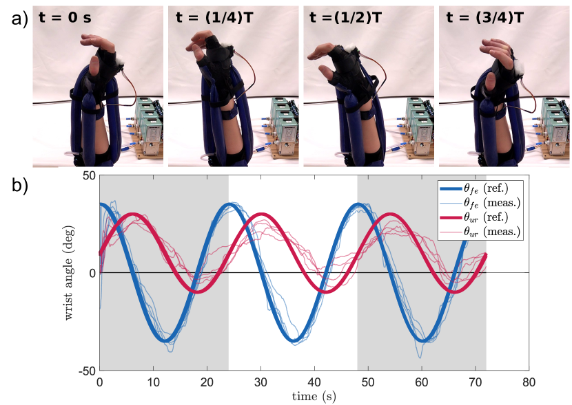
As a second demonstration, we studied how our controller can control the wrist motion along its two degrees of freedom. We defined a sinusoidal desired trajectory in joint space for both flexion/extension () and ulnar/radial deviation () angles to imitate the tracing of a near-elliptic trajectory by the hand. The amplitudes of the sinusoidal trajectories were defined to be within the range of motion such that the flexion/extension angles are between 40∘ and 30∘ and the ulnar/radial deviation angles are between 10∘ and 30∘. Both trajectories have a period of 24 seconds, but there is a 90∘ phase shift between them. Similarly to the other trajectory tracking task, the joint angles were set to zero at a neutral position of the wrist before starting the tracking.
The results of the spatial trajectory tracking are shown in Fig. 14. Fig. 14(a) illustrates the realized motion of the wrist by showing the wrist position on four equally spaced points of the trajectory. Fig. 14(b) shows the desired and four actual trajectories for the duration of three 24-second periods. It takes approximately 3.6 seconds to reach the desired trajectory after the start from the initial, zero position. This results in small disruptions compared to the targeted smooth motion. The root mean square angle error of the tracking (not including the short initial settling phase) is 5.18∘ for flexion/extension and 7.12∘ for ulnar/radial deviation.
VII Discussion
In this section, we discuss the results of the presented work, starting with the modeling of the exosuit-actuated torque, and then focusing on the experimental results and demonstration. We then present proposed movement assistance applications based on the observed properties of the exosuit.
VII-A Torque modeling and parameter optimization
We used a two-dimensional geometric model to describe the torque applied by the exosuit to the wrist at a given joint angle. The model assumes that the fPAM force acts in the plane perpendicular to a fixed rotational axis. For the exosuit prototype, however, the fPAM is not completely aligned to be in this plane, therefore the placement parameters describe the projection of the attachment point positions into this plane, which makes the parameter identification challenging. Additionally, the agonist and antagonist muscles, as well as the two pairs of antagonistic muscles, may interfere with each other when they are assigned to control flexion/extension and radial/ulnar deviation separately.
Another assumption we made is to model the wrist as a circle, which simplifies the geometric model, however, it assigns the same value (the value of ) to two different physical quantities, the distance from the center of rotation to the point where wrapping occurs, and the radius of curvature of the wrist surface. The model accuracy can be improved by modifying the model to assign separate parameters to these physical quantities.
The results of the parameter optimization showed that, at the pressure allowed by the current setup, the optimized placement parameters (Table I) were equal to the upper or lower bounds. When the fPAM force was increased by increasing the value of the pressure (Fig. 6), only changed, which indicates that, for the given user, we reached the optimal torque profile when the mounting points were placed as close as possible to the skin (minimal and ) and as far as possible from the wrist on the forearm (maximal ). Although these optimization results can be different for other users and different fPAM parameters, the current results highlight the importance of finding the right distance between the wrist and the mounting point on the hand () given the constraints on the pressure.
The optimization with doubled maximum pressure and the results of the perturbation of the exosuit parameters show that we can reach higher torque with increased fPAM parameters (Fig. 7(a)) and a larger range of motion when the placement parameters are adjusted (Fig. 7(b)). Therefore, it is advantageous to increase the internal pressure or the diameter of the fPAM. The increase of the diameter is only limited by the fact that the burst pressure decreases with the inverse of diameter, as well as the practical consideration of the increasing bulkiness as a larger fPAM is inflated. The input pressure is limited by the chosen pressure regulators or pressure source.
VII-B Results of the torque measurement
To evaluate the exosuit, we conducted a case study, where we compared the measured and modeled torque for the flexion fPAM with a single set of parameters for a single user. While this study does not give generalized data, it highlights some design challenges and key characteristics of the measured quantities.
The evaluation process, first, highlighted the importance of correctly identifying the fPAM parameters. The modeled force did not match the measured tensile testing data when we used the measured fully stretched radius () value, therefore this parameter had to be adjusted. Also, the force did not scale proportionally with the pressure due to the different maximum contraction ratio () values. For example, the magnitude of the force at 137 kPa pressure was similar to the force at 103 kPa because was smaller for 137 kPa. The tensile testing measurement proved to be a good method to calculate the parameters and, thus, to approximate the fPAM force with the model. However, it is important to conduct a more comprehensive analysis to understand the relationship between pressure and maximum contraction ratio. This relationship should be incorporated into the torque model to enhance its predictive capabilities, providing a more accurate assessment of how torque scales with pressure.
Compared to the measured torque, the modeled torque showed a mismatch especially for high wrist flexion angles when we directly used the actuator endpoint position data from the motion capture system (Fig. 10). One potential source of the model error is the inaccuracy of the endpoint tracking, as it is challenging to attach the markers directly to the end of the fPAM body close to the end-sealing knot. Additionally, another potential source of error is the inaccuracy regarding our method of mapping the 2D model to the human arm, as this mapping (e.g., the identification of the wrist angle) is not straightforward.
The second method of calculating the modeled torque allowed us to use the motion capture data only when the wrist is at the neutral angle by modeling the endpoint stretching. This significantly reduced the modeling error, leading to a better torque estimation through the flexion/extension angles, especially for high wrist flexion angles (Fig. 10). To achieve this accuracy, however, the wrist radius () and the stretching coefficients ( and ) need to be identified (e.g., through a calibration process).
The results of the torque measurement (Fig. 10) additionally show that the torque of the exosuit prototype is smaller than the optimized torque (Fig. 6), which highlights the challenges of fabricating the fPAM with the desired parameters (, , ) and interfacing the exosuit with the human upper limb. Firstly, the mounting points did not follow closely the optimal placement due to the restrictions from the measurement setup (e.g., the mounting point on the hand was moved further away from the wrist to not to be covered by the brackets of the hand plate). Secondly, the position of the mounting points changed due to stretching, which overall reduces the torque magnitude.
VII-C Results of the range of motion measurement
When measuring the biological range of motion, the user did not notice mechanical resistance from the exosuit. In comparison with the biological range of motion, we expected to get a similar exosuit actuated range in each movement direction, except for wrist flexion, as the measured torque profile showed that the flexor fPAM can not apply torque to move the wrist over approximately 50∘ of wrist flexion. The results (Table IV) confirmed the reduced range in wrist flexion, which was 44.5∘ compared to the biological 80.9∘. Similarly, in the case of wrist extension, the exosuit-actuated range was smaller than the biological (38.7∘ compared to 56.0∘), although proportionally it is closer to the biological range than the exosuit-actuated range for flexion. The range was smaller than the biological for ulnar/radial deviation as well (42.7∘ compared to 62.3∘), although not so significantly. This result was unexpected because the reduced range due to the increased distance (compared to the same distance in flexion/extension) was compensated by moving the mounting points closer to the wrist (decreased ).
We also found a mismatch between the measured and the modeled joint limits in all four directions of motion with the smallest error for the flexor fPAM (Table IV). This highlights the need to identify the parameters of the fPAM in use (the parameters used to model all the fPAMs were those of the flexor fPAM) and to conduct further work on refining the model and measurement process to be able to predict the range of motion.
For the current exosuit design, the refinement of the placement on the body and the reinforcement of the material of the glove and elbow band at the mounting points can increase the range of motion in all directions. In the case of wrist flexion, to reach the full biological range of motion, we need to find ways to increase the maximum contraction ratio of the fPAM.
VII-D Results of the control and demonstrations
For completing the trajectory tracking tasks, we used an antagonistic feedback control algorithm. The primary aim of the control system was to effectively demonstrate the exosuit’s capacity for achieving desired wrist configurations. Additionally, we analyzed the accuracy of the trajectory tracking to quantify the performance of the implemented control.
In the case of the planar positioning task (Fig. 13(b)), the actual joint angle reached the increased or decreased desired angles with a significant delay and overshoot. When the joint angle was increased, the desired position was reached with 0.84 s rise time and 19 overshoot. When the angle was decreased, the goal position was reached quicker with 0.54 s rise time, but the overshoot increased to 44. By using pressure feedback, the unit change of pressure causes a different change of the torque depending on the actual wrist angle, so the rate of change in the joint angle is not well regulated. This indicates that the applied feedback control with a constant gain could likely be improved to better adapt to such quick changes. The control algorithm is better suited for the spatial positioning task because the sinusoidal desired wrist angles change more gradually. In general, we observed that the exosuit with the implemented control was able to reach the desired wrist orientations, and it could resist small disturbances (e.g. when the biological hand resists the desired movement), but the accuracy of the trajectory tracking could likely be improved with different control methods.
VII-E Proposed movement assistance applications
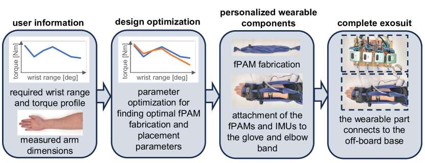
Wearable exosuits have multiple application areas. Based on the evaluation of the proposed exosuit design, our primary proposed application is for conducting rehabilitation exercises at home (e.g., stretching exercises for reducing spasticity). The wearable part of the exosuit is easy to fabricate and personalize for each user with the proposed pipeline shown in Fig. 15. The cost of the wearable part of the exosuit is low (approximately 134). The off-board base components have a significantly higher cost (approximately 3572 including a compressed air source), however, the same base can be used sequentially by multiple users. Also, the cost of all the components can be reduced, especially the pressure regulation components, which are the most expensive part of the base (approximately 3229).
The base is compact enough to bring the device home, along with a portable air compressor or pump, and it can remain stationary when performing the exercises. Due to the limited fPAM stretching and contraction, the exosuit can be designed to have hard-stop limits, which makes it safe to operate without the supervision of a professional. Also, with the introduced simple feedback control, the exosuit is able to perform exercises where the wrist is slowly moved along a pre-defined trajectory. Here, we only demonstrated the use of the exosuit for passively moving the wrist, but it could likely provide assistance and resistance as well. The observed limited torque and movement range in wrist flexion, however, restricts the usefulness of the exosuit for stretching across the full range of motion, therefore, further research should focus on overcoming this limitation (e.g., by increasing the maximum contraction ratio of the fPAM or by finding an alternative routing for the fPAMs).
The application of the exosuit as a movement assistive device for daily activities is currently limited because the base of the exosuit is not portable, so the user must be tethered while wearing the exosuit. Also, the implementation of more advanced control and sensing is necessary for this application. Compared to the currently used algorithm, the control should be improved to better utilize the quick dynamic response of the fPAM [18] and produce a quicker response of the exosuit. The physical capabilities of the device, however, seem to be satisfactory in providing assistance, because people do not use the full range of motion for most activities [6], and the required assistive torque for most activities is also smaller than the peak biological torque which was used as a reference in this work, so the discovered limitations in torque or range of motion might not limit the exosuit’s use.
VIII Conclusion
We presented a novel soft wrist exosuit with a symmetric arrangement of four fabric pneumatic artificial muscles to move the wrist in flexion/extension and ulnar/radial deviation. We introduced a two-dimensional model of the fPAM placement to calculate the torque applied by the exosuit to the wrist, and we developed a parameter optimization method for choosing the placement parameters. We optimized the model parameters to reach the peak torque of the human wrist in flexion/extension for a given user. The results show that, within the defined parameter bounds, the modeled exosuit torques are close to or higher than the biological reference torques, except for high wrist flexion angles over 46∘. To validate the model, we measured the torque that a flexor fPAM applies to the wrist. We derived the parameters of the fPAM by conducting a tensile testing measurement, and we determined the placement parameters by tracking the endpoint positions with a motion capture system. We modeled the torque both by using fixed position parameters and by including a model of fabric stretching at the mounting points. Compared to the former method, the latter method increased the accuracy of the model from 34.9% to 26.1% error. We also measured the biological and exosuit-assisted range of motion along the two degrees of freedom of the wrist, which confirmed the limited range primarily in wrist flexion. Finally, we demonstrated the capability of the exosuit to move the wrist, first, to a desired position in flexion/extension, and then to follow a desired trajectory in two degrees of freedom, using an antagonistic feedback control algorithm. The exosuit with the given control was able to track the desired trajectory with RMSE of 5.18∘ in flexion/extension and 7.12∘ in ulnar/radial deviation.
Our future work will explore how the exosuit can be used for at-home rehabilitation exercises (e.g., stretching) and movement assistance. Additionally, we aim to improve both the exosuit design and control based on the observations in Section VII to enhance the performance of the exosuit for the targeted applications.
IX Acknowledgements
We thank Mark Plecnik for providing access to the laser cutting and tensile testing machines used for experiments. Also, we thank Nicholas Naclerio for useful discussions about fabric pneumatic artificial muscles.
References
- [1] Y. Shen, P. W. Ferguson, and J. Rosen, “Upper limb exoskeleton systems—overview,” in Wearable Robotics, 2020, pp. 1–22.
- [2] H. S. Nam, H. G. Seo, J.-H. Leigh, Y. J. Kim, S. Kim, and M. S. Bang, “External robotic arm vs. upper limb exoskeleton: What do potential users need?” Applied Sciences, vol. 9, no. 12, p. 2471, 2019.
- [3] H. S. Lo and S. Q. Xie, “Exoskeleton robots for upper-limb rehabilitation: State of the art and future prospects,” Medical engineering & physics, vol. 34, no. 3, pp. 261–268, 2012.
- [4] C. Thalman and P. Artemiadis, “A review of soft wearable robots that provide active assistance: Trends, common actuation methods, fabrication, and applications,” Wearable Technologies, vol. 1, 2020.
- [5] A. F. Pérez Vidal, J. Y. Rumbo Morales, G. Ortiz Torres, F. d. J. Sorcia Vázquez, A. Cruz Rojas, J. A. Brizuela Mendoza, and J. C. Rodríguez Cerda, “Soft exoskeletons: Development, requirements, and challenges of the last decade,” Actuators, vol. 10, no. 7, p. 166, 2021.
- [6] A. K. Palmer, F. W. Werner, D. Murphy, and R. Glisson, “Functional wrist motion: a biomechanical study,” The Journal of Hand Surgery, vol. 10, no. 1, pp. 39–46, 1985.
- [7] T. Higuma, K. Kiguchi, and J. Arata, “Low-profile two-degree-of-freedom wrist exoskeleton device using multiple spring blades,” IEEE Robotics and Automation Letters, vol. 3, no. 1, pp. 305–311, 2017.
- [8] H. Choi, B. B. Kang, B.-K. Jung, and K.-J. Cho, “Exo-wrist: a soft tendon-driven wrist-wearable robot with active anchor for dart-throwing motion in hemiplegic patients,” IEEE Robotics and Automation Letters, vol. 4, no. 4, pp. 4499–4506, 2019.
- [9] N. Li, T. Yang, Y. Yang, P. Yu, X. Xue, X. Zhao, G. Song, I. H. Elhajj, W. Wang, N. Xi, and L. Liu, “Bioinspired musculoskeletal model-based soft wrist exoskeleton for stroke rehabilitation,” Journal of Bionic Engineering, vol. 17, no. 6, pp. 1163–1174, 2020.
- [10] D. Chiaradia, L. Tiseni, M. Xiloyannis, M. Solazzi, L. Masia, and A. Frisoli, “An assistive soft wrist exosuit for flexion movements with an ergonomic reinforced glove,” Frontiers in Robotics and AI, p. 182, 2021.
- [11] J. Jeong, I. B. Yasir, J. Han, C. H. Park, S.-K. Bok, and K.-U. Kyung, “Design of shape memory alloy-based soft wearable robot for assisting wrist motion,” Applied Sciences, vol. 9, no. 19, p. 4025, 2019.
- [12] H. Al-Fahaam, S. Davis, and S. Nefti-Meziani, “Wrist rehabilitation exoskeleton robot based on pneumatic soft actuators,” in International Conference for Students on Applied Engineering, 2016, pp. 491–496.
- [13] N. W. Bartlett, V. Lyau, W. A. Raiford, D. Holland, J. B. Gafford, T. D. Ellis, and C. J. Walsh, “A soft robotic orthosis for wrist rehabilitation,” Journal of Medical Devices, vol. 9, no. 3, 2015.
- [14] B. W. Ang and C.-H. Yeow, “Design and characterization of a 3D printed soft robotic wrist sleeve with 2 DoF for stroke rehabilitation,” in IEEE International Conference on Soft Robotics, 2019, pp. 577–582.
- [15] M. Zhu, W. Adams, and P. Polygerinos, “Carpal tunnel syndrome soft relief device for typing applications,” in Frontiers in Biomedical Devices, vol. 40672. American Society of Mechanical Engineers, 2017, p. V001T03A003.
- [16] S.-H. Park, J. Yi, D. Kim, Y. Lee, H. S. Koo, and Y.-L. Park, “A lightweight, soft wearable sleeve for rehabilitation of forearm pronation and supination,” in IEEE International Conference on Soft Robotics, 2019, pp. 636–641.
- [17] J. Realmuto and T. Sanger, “A robotic forearm orthosis using soft fabric-based helical actuators,” in IEEE International Conference on Soft Robotics, 2019, pp. 591–596.
- [18] N. Naclerio and E. W. Hawkes, “Simple, low-hysteresis, foldable, fabric pneumatic artificial muscle,” IEEE Robotics and Automation Letters, vol. 5, no. 2, pp. 3406–3413, 2020.
- [19] V. Sanchez, C. J. Walsh, and R. J. Wood, “Textile technology for soft robotic and autonomous garments,” Advanced Functional Materials, vol. 31, no. 6, p. 2008278, 2021.
- [20] B. Tondu, “Modelling of the mckibben artificial muscle: A review,” Journal of Intelligent Material Systems and Structures, vol. 23, no. 3, pp. 225–253, 2012.
- [21] M. Hallbeck, “Flexion and extension forces generated by wrist-dedicated muscles over the range of motion,” Applied ergonomics, vol. 25, no. 6, pp. 379–385, 1994.
- [22] K. Plewa, J. R. Potvin, and J. P. Dickey, “Wrist rotations about one or two axes affect maximum wrist strength,” Applied ergonomics, vol. 53, pp. 152–160, 2016.
- [23] R. Schmidt, C. Disselhorst-Klug, J. Silny, and G. Rau, “A marker-based measurement procedure for unconstrained wrist and elbow motions,” Journal of biomechanics, vol. 32, no. 6, pp. 615–621, 1999.
- [24] T. R. Kane, P. W. Likins, and D. A. Levinson, Spacecraft dynamics. McGraw‐Hill Book Company, 1983.