The Bragg demagnifier: X-ray imaging with kilometer propagation distance
within a meter
Abstract
We introduce a new X-ray imaging technique to facilitate propagation-based phase contrast of large, centimeter-sized samples. The diffracted X-ray wavefield behind the sample is demagnified by asymmetric Bragg crystal optics, thereby virtually increasing the propagation distance and thus enhancing the image contrast. We demonstrate the significant increase in image contrast compared to conventional phase contrast imaging at the same short physical propagation distance. Additionally, the Bragg demagnifier enables the reduction of image blur caused by the finite X-ray source size. In combination with a subsequent Bragg magnifier, the method will allow for an even higher dose efficiency, rendering this technique a potential candidate for, e.g., low-dose (bio)medical diagnostics.
Conventional X-ray imaging relies on the attenuation of X-rays in a medium and is well suited to highly-absorbing materials, but yields only vanishingly small contrast for soft materials and tissues [1]. Phase contrast imaging can overcome these limitations by uncovering the phase shift that the sample imprints on the X-ray wavefield [1, 2]. In the last decades, multiple phase contrast imaging techniques have been developed [3, 4, 5, 2, 6], finding application in various fields such as materials science [7], natural and cultural heritage [8], biology [9], industrial and medical applications [10, 11, 12, 13].
For phase contrast imaging of large, centimeter-sized samples at moderate resolution, it is essential to attain contrast at low spatial frequencies. This holds in particular for flux-limited applications such as low-dose or fast imaging, where a compromise has to be taken between deposited dose or exposure time on the one hand, and spatial resolution on the other hand.
There exist two main approaches for phase contrast imaging of large samples at moderate resolution above : differential phase contrast, e.g. analyzer- [14, 15], grating- [16, 17, 4] or speckle-based [18, 19], and propagation-based phase contrast imaging (PB-PCI) [20, 21, 22, 23, 24, 25, 26].
PB-PCI utilizes the coherent self-interference of the transmitted wavefield behind the sample, which gradually evolves into intensity contrast with increasing propagation distance.
However, to visualize low spatial frequencies of to , long propagation distances of ideally tens to hundreds of meters are necessary [23, 24, 25, 26, 27, 28, 29, 30]. Recently, a new beamline has been built at the European Synchrotron Radiation Facility (ESRF, Grenoble, France) with a remarkably long experimental hutch of , which facilitates PB-PCI at propagation distances of up to , tailored to the X-ray source size [31, 29, 32].
Here, we describe a new imaging technique that enables PB-PCI at moderate resolution with a physical distance between sample and detector in the sub-meter range, yet allowing for long effective propagation distances of hundreds to thousands of meters. For this purpose, the spatial frequency distribution of the diffracted X-ray wavefield behind the sample is magnified by asymmetric Bragg diffraction, resulting in a strongly increased effective propagation distance and thus increased image contrast. In the following, we outline the basic working principle, describe the realization by Bragg crystal optics and show a first proof-of-concept experiment.
The working principle is best understood in Fresnel diffraction and assuming monochromatic plane wave illumination of the sample. The complex-valued wavefield in the sample exit plane at can be represented by its Fourier transform , where and denote the spatial coordinate and angular spatial frequency, respectively. After free space propagation along a distance , the wavefield in the image plane is given by
| (1) |
where is the angular wave number in vacuum and is denoted as the Fresnel propagator [34]. The argument shows that low spatial frequencies in the wavefield need a large propagation distance to accumulate a certain phase shift, which can be converted into measurable intensity contrast. For imaging large samples at moderate resolution, it would thus be desirable to magnify the spatial frequencies of the sample exit wavefield in order to avoid tens to hundreds of meters physical propagation distance. By magnifying the spatial frequencies by a factor , the resulting wavefield is given by . Substitution of yields the wavefield
| (2) |
in the image plane after propagation of the modified wavefield along the physical distance .
The expansion of the frequency spectrum thus leads to an enhanced effective propagation distance that is quadratic in . The image acquired at the physical distance will therefore exhibit the same contrast as the unaltered wavefield after the propagation distance . By the term in Eq. 2 we recognize that the magnification of the spatial frequencies comes along with a demagnification in real space.
The demagnified image can either be detected by a high-resolution detector, which, however, has a limited detection efficiency, or it can be subsequently re-magnified for being detected with an efficient large-area detector [33], see also Appendix.
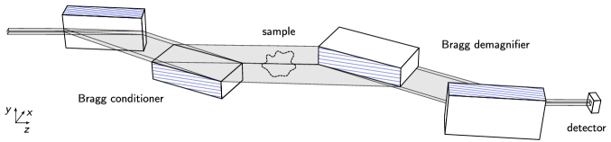
Demagnifying the X-ray wavefield with minimal distortion can be achieved by using a so-called Bragg magnifier with reversed optical path (see Fig. 1, right). A Bragg magnifier magnifies an X-ray wavefield by asymmetric Bragg diffraction [35, 36, 37, 38]. In this case, the asymmetry angle between the crystal surface and the reflecting lattice planes is defined as positive. In contrast, the wavefield is compressed when the asymmetry angle is negative. So far, demagnification by asymmetric Bragg diffraction has been used for focussing and collimating the incident X-ray illumination [39, 40], to achieve a high angular sensitivity in analyzer-based imaging [14] or to fit a large X-ray image onto a smaller detector [41]. Here, we use demagnification to specifically increase image contrast in PB-PCI. In our case, the Bragg demagnifier consists of two crystals for demagnification in - and -direction, respectively. The dependency between the spatial frequencies and of the wavefield in front of and behind the crystals is in general a slightly nonlinear function (see Appendix), causing the image formation to be shift-variant. In good approximation and to keep the discussion simple, we have , restoring the shift-invariance. As for the Bragg magnifier [37], the demagnification factor is given by
Here, is the asymmetry angle, the Bragg angle and and are refraction correcting terms from dynamical diffraction theory for the incident and outgoing wavefield, respectively [42].
Since the two crystals cannot be physically positioned at the same location but have a certain distance to each other, the horizontal and vertical compression of the wavefield occurs at different distances and along the optical axis between the sample and crystal centers. Likewise, the distances and between the crystal centers and the detector are different as well. The demagnified wavefield in the detector plane is given by
| with the propagator | ||||
In we have combined the complex crystal reflection of the diffracted wavefield amplitudes of both crystals [42]. and are the demagnification factors in horizontal and vertical direction, respectively. The different distances and potentially different magnifications lead to different effective propagation distances
in horizontal and vertical direction. For large , the propagation along in front of the crystals, i.e. before demagnification, can be neglected. Lastly, the highest resolvable spatial frequency is restricted by the angular acceptance of the crystals, i.e. the input Darwin width [42]. In accordance to Abbe’s criterion, it holds [43].
A prerequisite for imaging with a Bragg demagnifier is a monochromatic X-ray beam with sufficient transversal coherence and a large beam cross section to illuminate the sample.
In combination with a double-crystal monochromator, synchrotron beamlines of third and fourth generation provide low divergence and high monochromaticity. However, they usually offer only a limited, millimeter-sized beam cross section and finite transversal coherence at the sample position [44, 45, 46].
Here, we magnify the beam cross section in front of the sample by a Bragg magnifier, which we denote as Bragg conditioner (see Fig. 1 left) [47, 48, 49]. In addition, this Bragg conditioner further increases the transversal coherence and reduces the monochromatic beam divergence to well below the incident angular acceptance of the demagnifier.
Besides, such a Bragg conditioner has the ability to counteract energy dispersion effects of the Bragg demagnifier, as we will revisit later.
As a proof-of-concept, we realize a Bragg demagnifier for an energy range of . A schematic of the crystal arrangement is given in Fig. 1. The incident X-ray beam is expanded in two dimensions by a Bragg conditioner, traverses the sample, is demagnified by the Bragg demagnifier and propagates to the detector plane. We detect the final X-ray image with a high-resolution scintillator-based indirect detector (for details see Appendix). The vertical demagnification is performed first since the source size in third-generation synchrotrons is smaller in vertical direction than horizontally, allowing for larger propagation distances before the onset of source blur. The detector is placed at a distance of from the first crystal and from the second crystal. All crystals are composed of silicon (Si) and have an asymmetry angle of between the crystal surface normal and the crystallographic [110] direction. We operate the system at , where the demagnification factor for the Si 220 reflection is , resulting in effective propagation distances of and . The nominal resolution limit as introduced above is . The effective pixel size in the detector amounts to . For comparison to conventional free space propagation at the same physical distance, we acquire images without the demagnifier and using a large area detector of similar pixel size (, see Appendix), placed at from the sample.
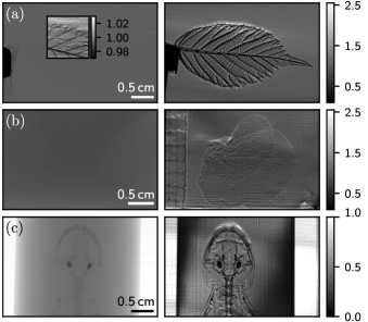
In Fig. 2, we display example images (after flat- and dark-field correction) of a blackberry leaf, a mouse liver lobe in an ethanol bag and a salamander in a tube filled with ethanol. For conventional PB-PCI, the leaf exhibits only very weak contrast caused by absorption in the sample, as shown in the inset, while the leaf veins become well visible with the demagnifier. The liver is not discernible at all in the conventional image. In contrast, the demagnifier brings to light a net of blood vessels due to the strongly increased propagation distance. A similar increase in contrast is observed for the salamander: in the conventional PB-PCI image, only the bones are weakly visible while the demagnifier reveals the internal structures. The stripes that appear mainly in the images of the liver lobe and the salamander result from crystal polishing artifacts in combination with drifts in the flat-field (empty beam).
The mechanical stability of our setup made the operation at an even higher magnification of and thus even larger propagation distances of challenging, since the demagnifier crystals have a very small angular acceptance (). For routine applications, the stability has to be further improved.
The images acquired with the Bragg demagnifier certainly show patterns that are brighter than the background, indicating constructive interference generated by PB-PCI. However, at the edges of the crystals where the background intensity is reduced, we observe also other bright patterns after flat-field correction, e.g. at the upper edge of the leaf and at the mouth of the salamander. These artifacts arise most likely from the curvature of the incident wavefield, which, at the crystal edges, deviates from the center of the crystal reflectivity curve, thereby generating diffraction-enhanced contrast [15]. In a future setup, the curvature may be reduced by collimating the X-ray beam in front of the Bragg conditioner by compound refractive lenses [51]. Further, the presented images partially contain extinction contrast as known from analyzer-based imaging [52], which occurs when X-rays are scattered to angles higher than the crystal’s angular acceptance and are thus not transferred into the image. We attribute for example the dark spots in the salamander, presumably in the otic region, not only to absorption but also to extinction contrast, since their intensity is reduced with the demagnifier. Extinction contrast is also observed in the bones.
Note that even though the angular acceptance of the demagnifier crystals is small and therefore sensitive for extinction contrast, there is no average intensity decrease in the soft tissue regions of the samples (Fig. 2). This implies that valuable information is encoded in low spatial frequencies within the angular acceptance, which are now made visible by the Bragg demagnifier through the enhanced PB-PCI.
In order to prove the presence of interference resulting from the increased effective propagation distance, we imaged a plastic spoon with a rough surface, which acts as a weak phase noise object. For weak phase objects, the contrast formation reduces to a linear process, and the image intensity in Fourier space is given by [53, 54]. Here, denotes the phase shift in Fourier space of the sample exit wavefield. The absorption enters similarly via the real part but is omitted here for clarity. Insertion of the propagator yields
| (3) |
where is a slowly varying correction from the complex crystal reflectivity. The conversion of phase information into image intensity defines the so-called phase contrast transfer function (PCTF). Analogously, replacing the sine by a cosine yields the amplitude contrast transfer function, which, however, only plays a minor role since is typically several orders of magnitude smaller than [55]. As a side note, Eq. 3 emphasizes the need for large propagation distances for imaging low spatial frequencies. As an example, Fig. 3a shows the free space PCTF for (brown). It generates almost no contrast. In contrast, a Bragg demagnifier with a demagnification factor of and a physical distance between crystal and detector of only exhibits high values in the PCTF (green). The PCTF corresponds to conventional free space propagation with a very large distance of , overlayed by the field amplitude reflection of the crystals (black).
In the Fourier spectrum of the plastic spoon so-called Thon rings become visible (Fig. 3b, c) [56]. They correspond to spatial frequencies where the PCTF is close to zero and are an additional evidence for the presence of interference effects. From the position of the Thon rings, we can extract a propagation distance of and , in correspondence with the experimental settings.
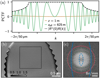
Next, we consider the effect of source blur on the image degradation. The monochromator delivers an energy distribution and a corresponding angular distribution given by the size of the polychromatic source. The virtual source size is typically increased when the X-rays pass through asymmetric crystals [57]. For our conditioner, we calculate a virtual spread by a factor of . Using matched crystals for the conditioner and demagnifier, the increase of the virtual source size can exactly be compensated [57]. This means that the demagnified image experiences the source blur of its physical propagation distance . Since the image was demagnified by a factor of , the source blur is a factor of better compared to the image blur at a physical propagation distance of . This effect is demonstrated in Fig. 3c. Assuming a Gaussian distribution for the source function, standard deviations of and in horizontal and vertical direction, respectively, have been extracted in preceding measurements. The resulting contrast degradation to at the physical propagation distance of and is depicted by the solid blue line. A hypothetical physical propagation distance of without demagnifier would suppress most of the image information, as shown by the dashed blue line. For completeness, we also indicate the degradation by the optical transfer function of the indirect detector system, see [33]. The formation of additional Thon rings in vertical direction may further be suppressed since the spoon does not deliver a white noise power spectrum.
Instead of detecting the demagnified image with a high-resolution detector, the wavefield can also be re-magnified with a Bragg magnifier and detected by a highly-efficient large-area detector [33]. In this way, the Bragg demagnifier would enable imaging at moderate resolution with an even higher dose efficiency. Moreover, the shift-variance is exactly compensated when using the same crystals as for the demagnifier (see Appendix), allowing the image formation to be efficiently modeled in Fourier space.
In summary, we have presented a novel imaging technique to facilitate propagation-based X-ray phase contrast imaging of large, centimeter-sized samples at moderate resolution. By demagnifying the X-ray wavefield behind the sample with a Bragg demagnifier, the effective propagation distance is strongly increased. Thereby, the image contrast is significantly enhanced compared to phase contrast imaging at the same physical propagation distance, as we verified experimentally. Simultaneously, image blur by the finite source size is reduced. For the illumination of the sample, a Bragg conditioner is used in front of the sample to enlarge the beam cross section of the millimeter-sized synchrotron beam, thereby also increasing the monochromatic transversal coherence. By magnifying the propagated wavefield with a Bragg magnifier onto an efficient large-area detector, the technique may find utility for dose-efficient applications, e.g. in medical diagnostics in conjunction with compact X-ray sources [58, 59, 60, 61] for the early detection of breast cancer or other diseases. In future, the mechanical stability has to be further improved before larger crystals and higher energies as well as the combination with an additional Bragg magnifier can be investigated.
I Acknowledgments:
We acknowledge DESY (Hamburg, Germany), a member of the Helmholtz Association HGF, for the provision of experimental facilities. Parts of this research were carried out at P23, PETRA III, in the frame of the KIT-DESY ’Hierarchical Imaging Karlsruhe’ collaboration, and we would like to thank Carlos Sato Baraldi Dias, Mateusz Czyzycki and Dmitri Novikov for assistance at the beamline. We are grateful to Simon Merz, Lea Bornemann (both Miltenyi Biotec) and Quentin Martinez (Stuttgart State Museum of Natural History) for providing the mouse liver lobe and salamander specimen, respectively. Further, we thank Stefan Uhlemann and Tobias Hilvering for technical assistance as well as Stephen Doyle for language revision. The research was funded by the German Federal Ministry of Education and Research via grant 05K2019 (HIGH-LIFE).
References
- Salditt et al. [2017] T. Salditt, T. Aspelmeier, and S. Aeffner, Biomedical Imaging (De Gruyter, Berlin, Germany, 2017) p. 244ff.
- Endrizzi [2018] M. Endrizzi, X-ray phase-contrast imaging, Nuclear instruments and methods in physics research section A: Accelerators, spectrometers, detectors and associated equipment 878, 88 (2018).
- Chapman and Nugent [2010] H. N. Chapman and K. A. Nugent, Coherent lensless X-ray imaging, Nature Photonics 4, 833 (2010).
- Pfeiffer et al. [2013] F. Pfeiffer, J. Herzen, M. Willner, M. Chabior, S. Auweter, M. Reiser, and F. Bamberg, Grating-based X-ray phase contrast for biomedical imaging applications, Z. Med. Phys. 23, 176 (2013).
- Lider and Kovalchuk [2013] V. V. Lider and M. V. Kovalchuk, X-ray phase-contrast methods, Crystallogr. Rep. 58, 769 (2013).
- Tao et al. [2021] S. Tao, C. He, X. Hao, C. Kuang, and X. Liu, Principles of Different X-ray Phase-Contrast Imaging: A Review, Appl. Sci. 11, 2971 (2021).
- Mayo et al. [2012] S. C. Mayo, A. W. Stevenson, and S. W. Wilkins, In-line phase-contrast X-ray imaging and tomography for materials science, Materials 5, 937 (2012).
- Cotte et al. [2019] M. Cotte, P.-O. Autran, C. Berruyer, C. Dejoie, J. Susini, and P. Tafforeau, Cultural and natural heritage at the esrf: Looking back and to the future, Synchrotron Radiation News 32, 34 (2019).
- Betz et al. [2007] O. Betz, U. Wegst, D. Weide, M. Heethoff, L. Helfen, W.-K. Lee, and P. Cloetens, Imaging applications of synchrotron X-ray phase-contrast microtomography in biological morphology and biomaterials science. I. General aspects of the technique and its advantages in the analysis of millimetre-sized arthropod structure, J. Microsc. 227, 51 (2007).
- Kastner et al. [2017] J. Kastner, C. Heinzl, B. Plank, D. Salaberger, C. Gusenbauer, and S. Senck, New X-ray computed tomography methods for research and industry, in 7th Conference on Industrial Computed Tomography (iCT2017) (2017).
- Lewis [2004] R. A. Lewis, Medical phase contrast X-ray imaging: current status and future prospects, Physics in medicine & biology 49, 3573 (2004).
- Bravin et al. [2012] A. Bravin, P. Coan, and P. Suortti, X-ray phase-contrast imaging: from pre-clinical applications towards clinics, Phys. Med. Biol. 58, R1 (2012).
- Taba et al. [2018] S. T. Taba, T. E. Gureyev, M. Alakhras, S. Lewis, D. Lockie, and P. C. Brennan, X-ray Phase-Contrast Technology in Breast Imaging: Principles, Options, and Clinical Application, American Journal of Roentgenology 211, 133 (2018).
- Davis et al. [1995a] T. J. Davis, D. Gao, T. Gureyev, A. Stevenson, and S. Wilkins, Phase-contrast imaging of weakly absorbing materials using hard X-rays, Nature 373, 595 (1995a).
- Chapman et al. [1997] D. Chapman, W. Thomlinson, R. Johnston, D. Washburn, E. Pisano, N. Gmür, Z. Zhong, R. Menk, F. Arfelli, and D. Sayers, Diffraction enhanced X-ray imaging, Physics in Medicine & Biology 42, 2015 (1997).
- David et al. [2002] C. David, B. Nöhammer, H. H. Solak, and E. Ziegler, Differential X-ray phase contrast imaging using a shearing interferometer, Appl. Phys. Lett. 81, 3287 (2002).
- Momose et al. [2003] A. Momose, S. Kawamoto, I. Koyama, Y. Hamaishi, K. Takai, and Y. Suzuki, Demonstration of X-ray talbot interferometry, Japanese Journal of Applied Physics 42, L866 (2003).
- Morgan et al. [2012] K. S. Morgan, D. M. Paganin, and K. K. W. Siu, X-ray phase imaging with a paper analyzer, Appl. Phys. Lett. 100, 10.1063/1.3694918 (2012).
- Zdora [2018] M.-C. Zdora, State of the Art of X-ray Speckle-Based Phase-Contrast and Dark-Field Imaging, J. Imaging 4, 60 (2018).
- Snigirev et al. [1995] A. Snigirev, I. Snigireva, V. Kohn, S. Kuznetsov, and I. Schelokov, On the possibilities of X-ray phase contrast microimaging by coherent high-energy synchrotron radiation, Review of Scientific Instruments 66, 5486 (1995).
- Wilkins et al. [1996] S. W. Wilkins, T. E. Gureyev, D. Gao, A. Pogany, and A. W. Stevenson, Phase-contrast imaging using polychromatic hard X-rays, Nature 384, 335 (1996).
- Cloetens et al. [1999] P. Cloetens, W. Ludwig, J. Baruchel, D. Van Dyck, J. Van Landuyt, J. Guigay, and M. Schlenker, Holotomography: Quantitative phase tomography with micrometer resolution using hard synchrotron radiation X rays, Applied Physics Letters 75, 2912 (1999).
- Zamir et al. [2016] A. Zamir, O. J. Arthurs, C. K. Hagen, P. C. Diemoz, T. Brochard, A. Bravin, N. J. Sebire, and A. Olivo, X-ray phase contrast tomography; proof of principle for post-mortem imaging, The British Journal of Radiology 89, 20150565 (2016).
- Wagner et al. [2018] W. L. Wagner, F. Wuennemann, S. Pacilé, J. Albers, F. Arfelli, D. Dreossi, J. Biederer, P. Konietzke, W. Stiller, M. O. Wielpütz, et al., Towards synchrotron phase-contrast lung imaging in patients - a proof-of-concept study on porcine lungs in a human-scale chest phantom, Journal of Synchrotron Radiation 25, 1827 (2018).
- Donnelley et al. [2019] M. Donnelley, K. S. Morgan, R. Gradl, M. Klein, D. Hausermann, C. Hall, A. Maksimenko, and D. W. Parsons, Live-pig-airway surface imaging and whole-pig CT at the Australian Synchrotron Imaging and Medical Beamline, Journal of Synchrotron Radiation 26, 175 (2019).
- Walsh et al. [2021] C. Walsh, P. Tafforeau, W. Wagner, D. Jafree, A. Bellier, C. Werlein, M. Kühnel, E. Boller, S. Walker-Samuel, J. Robertus, et al., Imaging intact human organs with local resolution of cellular structures using hierarchical phase-contrast tomography, Nature Methods 18, 1532 (2021).
- Tavakoli et al. [2021] C. Tavakoli, E. Cuccione, C. Dumot, D. Cormode, M. Wiart, H. Elleaume, and E. Brun, Tracking cells in the brain of small animals using synchrotron multi-spectral phase contrast imaging, in Medical Imaging 2021: Physics of Medical Imaging, Vol. 11595 (SPIE, 2021) pp. 1218–1224.
- Arhatari et al. [2021] B. D. Arhatari, A. W. Stevenson, B. Abbey, Y. I. Nesterets, A. Maksimenko, C. J. Hall, D. Thompson, S. C. Mayo, T. Fiala, H. M. Quiney, et al., X-ray phase-contrast computed tomography for soft tissue imaging at the imaging and medical beamline (IMBL) of the Australian Synchrotron, Applied Sciences 11, 4120 (2021).
- Cotte et al. [2022] M. Cotte, K. Dollman, V. Fernandez, V. Gonzalez, F. Vanmeert, L. Monico, C. Dejoie, M. Burghammer, L. Huder, S. Fisher, et al., New Opportunities Offered by the ESRF to the Cultural and Natural Heritage Communities, Synchrotron Radiation News 35, 3 (2022).
- Häggmark et al. [2023] I. Häggmark, K. Shaker, S. Nyrén, B. Al-Amiry, E. Abadi, W. P. Segars, E. Samei, and H. M. Hertz, Phase-contrast virtual chest radiography, Proceedings of the National Academy of Sciences 120, e2210214120 (2023).
- Cianciosi et al. [2021] F. Cianciosi, A.-L. Buisson, P. Tafforeau, and P. Van Vaerenbergh, BM18, the New ESRF-EBS Beamline for Hierarchical Phase-Contrast Tomography (JACOW Publishing, Geneva, Switzerland, 2021).
- Lang et al. [2023] T. Lang, N. Saeidnezhad, K. Dremel, D. Weller, M. Diez, A. M. Stock, T. Sauer, F. Cianciosi, C. Jarnias, P. Tafforeau, and S. Zabler, Multiscale Phase-Contrast Tomography at BM18, e-Journal of Nondestructive Testing 28 (2023).
- Spiecker et al. [2023] R. Spiecker, P. Pfeiffer, A. Biswal, M. Shcherbinin, M. Spiecker, H. Hessdorfer, M. Hurst, Y. Zharov, V. Bellucci, T. Farago, M. Zuber, A. Herz, A. Cecilia, M. Czyzycki, C. Dias, D. Novikov, L. Krogmann, E. Hamann, T. van de Kamp, and T. Baumbach, Dose-efficient in vivo X-ray phase contrast imaging at micrometer resolution, Optica 10.1364/OPTICA.500978 (2023).
- Cowley [1978] J. M. Cowley, Electron Microdiffraction, in Advances in Electronics and Electron Physics, Vol. 46 (Academic Press, Cambridge, MA, USA, 1978) pp. 1–53.
- Boettinger et al. [1979] W. J. Boettinger, H. E. Burdette, and M. Kuriyama, X-ray magnifier, Review of Scientific Instruments 50, 26 (1979).
- Kobayashi et al. [2001] K. Kobayashi, K. Izumi, H. Kimura, S. Kimura, T. Ibuki, Y. Yokoyama, Y. Tsusaka, Y. Kagoshima, and J. Matsui, X-ray phase-contrast imaging with submicron resolution by using extremely asymmetric Bragg diffractions, Applied Physics Letters 78, 132 (2001).
- Stampanoni et al. [2002] M. Stampanoni, G. Borchert, R. Abela, and P. Rüegsegger, Bragg magnifier: A detector for submicrometer X-ray computer tomography, Journal of Applied Physics 92, 7630 (2002).
- Modregger et al. [2006] P. Modregger, D. Lübbert, P. Schäfer, and R. Köhler, Magnified X-ray phase imaging using asymmetric Bragg reflection: Experiment and theory, Physical Review B 74, 054107 (2006).
- Watanabe et al. [1999] N. Watanabe, M. Suzuki, Y. Higashi, and N. Sakabe, Rotated-inclined focusing monochromator with simultaneous tuning of asymmetry factor and radius of curvature over a wide wavelength range, Journal of Synchrotron Radiation 6, 64 (1999).
- Tsusaka et al. [2000] Y. Tsusaka, K. Yokoyama, S. Takeda, M. Urakawa, Y. Kagoshima, J. Matsui, S. Kimura, H. Kimura, K. Kobayashi, and K. Izumi, Formation of parallel X-ray microbeam and its application, Japanese Journal of Applied Physics 39, L635 (2000).
- Hirano and Takahashi [2013] K. Hirano and Y. Takahashi, Applications of X-ray magnifier and demagnifier to angle-resolved X-ray computed tomography, in Journal of Physics: Conference Series, Vol. 425 (IOP Publishing, 2013) p. 192004.
- Authier [2004] A. Authier, Dynamical theory of X-ray diffraction, Vol. 11 (Oxford University Press Inc., New York, United States, 2004) p. 189ff.
- Abbe [1873] E. Abbe, Beiträge zur Theorie des Mikroskops und der mikroskopischen Wahrnehmung, Archiv für mikroskopische Anatomie 9, 413 (1873).
- Martinson et al. [2015] M. Martinson, N. Samadi, B. Bassey, A. Gomez, and D. Chapman, Phase-preserving beam expander for biomedical X-ray imaging, J. Synchrotron Radiat. 22, 801 (2015), 25931100 .
- Márkus et al. [2018] O. Márkus, I. Greving, E. Kornemann, M. Storm, F. Beckmann, J. Mohr, and A. Last, Optimizing illumination for full field imaging at high brilliance hard X-ray synchrotron sources, Optics express 26, 30435 (2018).
- Reinhard et al. [2021] C. Reinhard, M. Drakopoulos, S. I. Ahmed, H. Deyhle, A. James, C. M. Charlesworth, M. Burt, J. Sutter, S. Alexander, P. Garland, et al., Beamline K11 DIAD: A new instrument for dual imaging and diffraction at Diamond Light Source, Journal of Synchrotron Radiation 28, 1985 (2021).
- Matsushita and Hashizume [1983] T. Matsushita and H. Hashizume, Handbook on Synchrotron Radiation, edited by E. Koch, Vol. 1 (North Holland Publishing Company, 1983) Chap. 4.
- Christensen et al. [1994] F. E. Christensen, A. Hornstrup, P. K. Frederiksen, S. Abdali, P. Grundsoe, H. W. Schnopper, R. A. Lewis, C. J. Hall, and K. N. Borozdin, Expanded beam X-ray optics calibration facility at the Daresbury Synchrotron, in Multilayer and Grazing Incidence X-ray/EUV Optics II, Vol. 2011 (SPIE, 1994) pp. 540–548.
- Kamezawa et al. [2023] C. Kamezawa, K. Hyodo, C. Tokunaga, T. Tsukada, and S. Matushita, Large-view X-ray imaging for medical applications using the world’s only vertically polarized synchrotron radiation beam and a single asymmetric Si crystal, Phys. Med. Biol. 68, 195010 (2023).
- Davis et al. [1995b] T. J. Davis, T. E. Gureyev, D. Gao, A. W. Stevenson, and S. W. Wilkins, X-ray Image Contrast from a Simple Phase Object, Phys. Rev. Lett. 74, 3173 (1995b).
- Shastri [2004] S. D. Shastri, Combining flat crystals, bent crystals and compound refractive lenses for high-energy X-ray optics, Journal of Synchrotron Radiatiation 11, 150 (2004).
- Bravin [2003] A. Bravin, Exploiting the X-ray refraction contrast with an analyser: the state of the art, Journal of Physics D: Applied Physics 36, A24 (2003).
- Lenz and Scheffels [1958] F. Lenz and W. Scheffels, Das Zusammenwirken von Phasen- und Amplitudenkontrast in der elektronenmikroskopischen Abbildung, Zeitschrift für Naturforschung A 13, 226 (1958).
- Kirkland [2020] E. J. Kirkland, Some Image Approximations, in Advanced Computing in Electron Microscopy (Springer, Cham, Switzerland, 2020) pp. 37–80.
- Momose and Fukuda [1995] A. Momose and J. Fukuda, Phase-contrast radiographs of nonstained rat cerebellar specimen, Medical Physics 22, 375 (1995).
- Thon [1966] F. Thon, Zur Defokussierungsabhängigkeit des Phasenkontrastes bei der elektronenmikroskopischen Abbildung, Zeitschrift für Naturforschung A 21, 476 (1966).
- Huang et al. [2012] X. Huang, A. Macrander, M. Honnicke, Y. Cai, and P. Fernandez, Dispersive spread of virtual sources by asymmetric X-ray monochromators, Journal of Applied Crystallography 45, 255 (2012).
- Huang and Ruth [1998] Z. Huang and R. D. Ruth, Laser-electron storage ring, Physical Review Letters 80, 976 (1998).
- Bech et al. [2009] M. Bech, O. Bunk, C. David, R. Ruth, J. Rifkin, R. Loewen, R. Feidenhans’l, and F. Pfeiffer, Hard X-ray phase-contrast imaging with the Compact Light Source based on inverse Compton X-rays, Journal of Synchrotron Radiation 16, 43 (2009).
- Günther et al. [2020] B. Günther, R. Gradl, C. Jud, E. Eggl, J. Huang, S. Kulpe, K. Achterhold, B. Gleich, M. Dierolf, and F. Pfeiffer, The versatile X-ray beamline of the Munich Compact Light Source: design, instrumentation and applications, Journal of Synchrotron Radiation 27, 1395 (2020).
- Hornberger et al. [2021] B. Hornberger, J. Kasahara, R. Ruth, R. Loewen, and J. Khaydarov, Inverse compton scattering X-ray source for research, industry and medical applications, in International Conference on X-ray Lasers 2020, Vol. 11886 (SPIE, 2021) pp. 51–60.
- Modregger et al. [2008] P. Modregger, D. Lübbert, P. Schäfer, R. Köhler, T. Weitkamp, M. Hanke, and T. Baumbach, Fresnel diffraction in the case of an inclined image plane, Opt. Express 16, 5141 (2008).
- Hrivňak et al. [2018] S. Hrivňak, J. Uličnỳ, and P. Vagovič, Fast Fresnel propagation through a set of inclined reflecting planes applicable for X-ray imaging, Optics Express 26, 34569 (2018).
- Vagovič et al. [2014] P. Vagovič, L. Švéda, A. Cecilia, E. Hamann, D. Pelliccia, E. Gimenez, D. Korytár, K. M. Pavlov, Z. Zápražnỳ, M. Zuber, et al., X-ray bragg magnifier microscope as a linear shift invariant imaging system: image formation and phase retrieval, Optics Express 22, 21508 (2014).
- Hrivňak et al. [2016] S. Hrivňak, J. Uličnỳ, L. Mikeš, A. Cecilia, E. Hamann, T. Baumbach, L. Švéda, Z. Zápražnỳ, D. Korytár, E. Gimenez-Navarro, et al., Single-distance phase retrieval algorithm for bragg magnifier microscope, Optics Express 24, 27753 (2016).
- [66] R. Spiecker, Dissertation, in preparation, 10.5445/IR/1000162889.
- Douissard et al. [2012] P.-A. Douissard, A. Cecilia, X. Rochet, X. Chapel, T. Martin, T. van de Kamp, L. Helfen, T. Baumbach, L. Luquot, X. Xiao, et al., A versatile indirect detector design for hard X-ray microimaging, Journal of Instrumentation 7 (09), P09016.
- Vogelgesang et al. [2016] M. Vogelgesang, T. Farago, T. F. Morgeneyer, L. Helfen, T. dos Santos Rolo, A. Myagotin, and T. Baumbach, Real-time image-content-based beamline control for smart 4D X-ray imaging, Journal of Synchrotron Radiation 23, 1254 (2016).
Supplementary Material
Appendix A Shift (in)variance
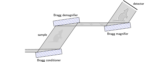
In a shift-invariant imaging system, a translation of the object yields the same image, besides a displacement. In contrast, Bragg crystal optics are in general shift-variant imaging systems [62, 63]. Due to asymmetric reflection a lateral translation of the wavefield leads to different propagation distances, which is a complication for phase retrieval [64, 65]. For coplanar diffraction of a plane wave on a crystal surface, the relation between the incident and outgoing spatial frequencies and is given by [66]
where and are the angles between the crystal surface and the incident or outgoing optical axis, respectively. These angles can be computed from dynamical diffraction theory [42]. As mentioned in the main text, the shift-invariance of the demagnifier can be restored by adding a matched Bragg magnifier downstream (see Fig. S1). This can be best understood in Fourier space. A plane wave with spatial frequency incident on the demagnifier results in a plane wave with the same spatial frequency behind the magnifier. Only the phase and amplitude are altered by the crystals and the free space propagation. Consequently, the modulation of the propagated wavefield can be described by a transfer function, i.e. the propagated wavefield is given by a convolution of the incident wavefield with a coherent point-spread function.
Appendix B Details on the experimental setup
The experimental data were acquired at the beamline P23 at PETRA III, DESY, Hamburg. All four Si crystals used in the experiment have dimensions of x x and a nominal asymmetry angle of . The calculated imaging parameters of the Bragg demagnifier crystals are given in Table S1 for energies between to . Each crystal was mounted on a high-precision hexapod (Physik Instrumente (PI) GmbH & Co. KG, 76228 Karlsruhe, Germany). For acquiring images with the Bragg demagnifier, we used an indirect detector system with a thick LSO:Tb scintillator, a diffraction-limited optical microscope (Optique Peter, 69210 Lentilly, France), a 5x objective lens with a numerical aperture of 0.14 (model 378-803-3, Mitutoyo Deutschland GmbH, 41469 Neuss, Germany), a tubus lens resulting in 4.5x total optical magnification [67], and a pco.edge 5.5 CMOS camera (PCO AG, 93309 Kelheim, Germany) with an exposure time of and a physical pixel size of x , yielding an effective pixel size of in the image plane. Combined with the demagnification factor of at , the pixel size amounts to in the object plane. For the conventional PB-PCI acquisitions, a Shad-o-Box 1K HS (Teledyne Dalsa, Waterloo, Canada) was placed downstream of the sample. To prevent saturation of the camera, we had to attenuate the beam by a factor of 500. The presented images for conventional PB-PCI were acquired with an exposure time of averaged over 20 acquisitions. For data acquisition and motor control, we used the control system Concert [68]. The tiger salamander (Ambystoma tigrinum) utilized in the experiment is a museum specimen that was loaned for our experiment. The mouse liver was obtained from The Jackson Laboratory, US. Both specimens were fixed in PFA and subsequently stored in ethanol.
| energy (keV) | resolution limit () | demagnification | gain factor |
|---|---|---|---|
| 29.0 | 68 | 25.7 | 660 |
| 30.0 | 91 | 45.4 | 2061 |
| 30.5 | 116 | 71.4 | 5098 |
| 31.0 | 190 | 144.7 | 20938 |