Femtosecond laser fabricated nitinol living hinges for millimeter-sized robots
Abstract
Nitinol is a smart material that can be used as an actuator, a sensor, or a structural element, and has the potential to significantly enhance the capabilities of microrobots. Femtosecond laser technology can be used to process nitinol while avoiding heat-affected zones (HAZ), thus retaining superelastic properties. In this work, we manufacture living hinges of arbitrary cross-sections from nitinol using a femtosecond laser micromachining process. We first determined the laser cutting parameters, fluence with passes for ablation, by varying laser power level and number of passes. Next, we modeled the hinges using an analytical model as well as creating an Abaqus finite element method, and showed the accuracy of the models by comparing them to the torque produced by eight different hinges, four with a rectangular cross-section and four with an arc cross-section. Finally, we manufactured three prototype miniature devices to illustrate the usefulness of these nitinol hinges: a sample spherical 5-bar mechanism, a sarrus linkage, and a piezoelectric actuated robotic wing mechanism.
I Introduction
Miniature robots are becoming increasingly relevant for a variety of real world applications including search-and-rescue [1], high-value asset inspection and maintenance [2], environmental monitoring [3] and healthcare [4]. While tremendous progress has been made in the rapid prototyping of millimeter-scale devices, especially with respect to 3D printing [5] and laminate stack manufacturing [6], both have significant issues currently limiting wider adoption. 3D printing is limited by choice of materials and scale of printing, trading off resolution of fine features with overall build volume [5]. On the other hand, laminate stack manufacturing allows combining multiple materials, but the typical design process is often complex and is limited to the planar processing of thin films [7]. For example, to make a symmetrically bending hinge, one typically needs to combine at least five layers - two structural, two adhesive, and one flexible [8]. Moreover, the flexible layer may contain through-hole features but cannot support 3D contouring. This creates bidirectional flexures which are ideal for bending about a single axis but have off-axis compliance that cannot be tuned easily, resulting in less than ideal robot dynamics. For example, flexures of climbing [2], high speed running [9], and flying robots have a small elastic deflection range (0.8% elastic strain limit for polyimide Kapton compared to 4-10% for nitinol [10]) and limited lifetime (100s for the flying robot from Kim, et al. [11]) resulting in poor overall performance. Therefore, addressing the grand challenge of developing novel materials and new fabrication schemes [12] which increase the available choices to robotic designers is instrumental in realizing the next generation of highly capable robots [13].
Our group [14, 15] is specifically interested in exploring the potential of using nitinol for microrobotics [16, 17]. Nitinol, a nickel-titanium alloy, has a wide variety of unique properties that make it useful for many different applications at larger scales. Some of these properties include superelasticity, shape memory, high kink and fatigue resistance, non-linear stiffness, and biocompatibility. These properties, especially biocompatibility, have led to nitinol becoming increasingly used in medical devices, such as for stents, filters, scissors, grabbers, and more [18, 19]. Additionally, nitinol can be used as an actuator (shape memory) or high-deformation flexure (superelasticity) in various applications in the robotics [20], precision medicine [21], aerospace [22], and automotive [23] industries. We believe a custom-machined three-dimensional nitinol flexure fabricated at millimeter sizes can potentially address many of the concerns described previously to enable further miniaturization of insect-scale devices beyond their current sizes [24]. So far, nitinol has been demonstrated to be effectively used as a structural material [25, 26], an actuator [27, 28] and/or a sensor [29, 30] in miniature designs. Such multifunctionality makes it particularly attractive for monolithic fabrication and miniaturization of microscale devices.
However, nitinol is a notoriously difficult material to machine. Rapid work hardening can grind down mechanical tools or require a manufacturer to anneal the material, a time-consuming process [31]. Applying heat shaping techniques to process nitinol is a possibility, but often expensive and complex [31]. Typical laser cutting machines for photomicromachining utilize micro- or nano- second laser pulses which create heat-affected zones (HAZ). HAZ negatively affects the superelasticity and/or shape memory of the bulk material thus making the material unusable for high-performance applications [32]. Abrasive jet machining is an effective manufacturing technique for this material as recently demonstrated, but it cannot yet accurately produce the high-resolution (e.g. few microns) complex features (e.g. geometries with varying cross-sections) essential for microrobotic devices [33]. Furthermore, nitinol has a relatively small critical crack size, so fatigue life is driven by crack initiation instead of crack propagation. Thus, increased care must be taken to reduce the likelihood of crack formation while working with nitinol [34].
Femtosecond laser technology has recently emerged as a rapid manufacturing technique to process nitinol accurately while avoiding HAZ [32, 35, 36, 37]. Due to the incredibly short laser pulse width ( fs), the material is ’cold ablated’ rather than melted away resulting in machined material retaining its bulk properties for the most part [37]. Despite the benefits of machining nitinol with a femtosecond laser, few examples of this manufacturing method exist in the literature [35, 37], primarily due to the expensive cost of femtosecond lasers and associated optics. However, with this technology becoming significantly cheaper in the last five years, femtosecond laser micromachines are starting to become commercially available (e.g. 6D Laser, LLC111www.6dlasers.com).
In this work, we explore the idea of creating nitinol living hinges using a custom femtosecond laser micromachine. This motivation is driven by the knowledge that living hinges are one of the fundamental building blocks of compliant mechanisms and in general reduce the size, part count, and energy losses compared to traditional mechanisms [38, 39, 40]. We demonstrate laser manufacturing of nitinol living hinges with arbitrary cross-sections. We then characterize these hinges by measuring their torque-angle relationship. We model the fabricated living hinges using theory and finite element analysis and show that our experimental data match these models. Finally, we design and test a miniature robotic wing mechanism as a demonstration of our process and highlight its potential in the rapid prototyping of insect-scale flying robots. We conclude by presenting future development, as we expect to further improve the manufacturing process for the nitinol hinges and integrate them into millimeter-scale robot and medical devices that would benefit from hinges with high displacement.
II Femtosecond Laser Micromachining
In this section, we detail the fabrication process used to manufacture nitinol living hinges. We fabricated our hinges using a thick superelastic nitinol sheet with a transition temperature of (Nexmetal Corp.).
II-A Laser Micromachining Setup
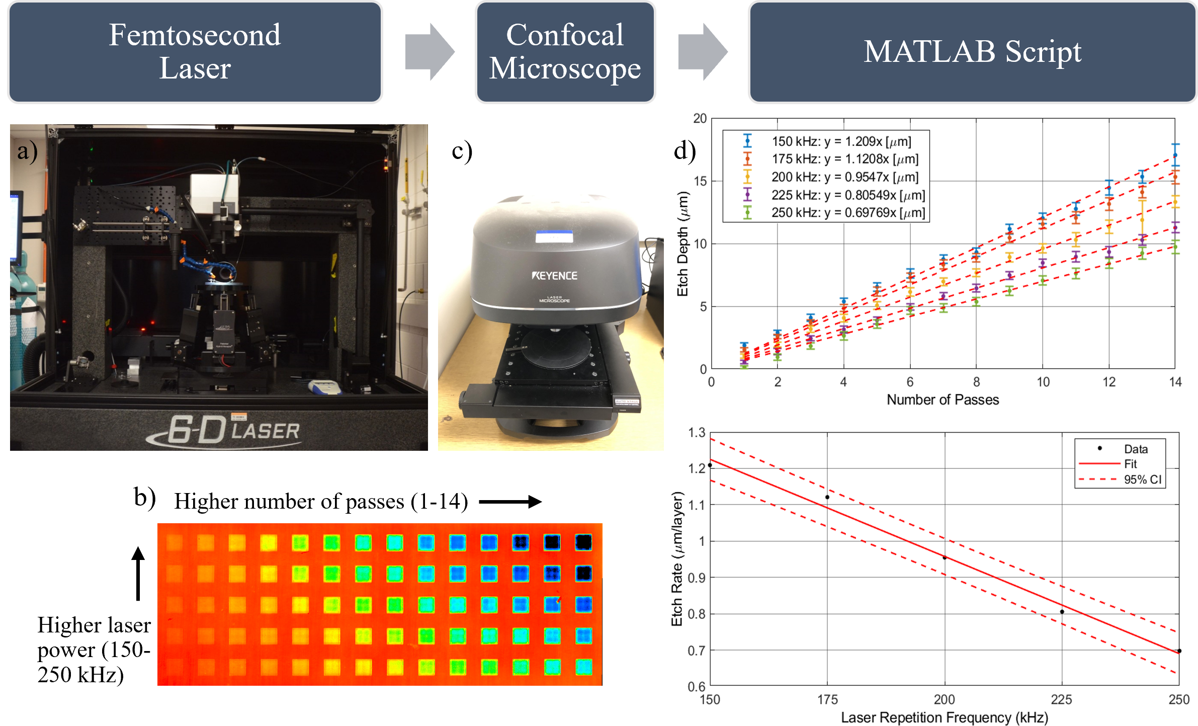
Our custom laser micromachine (6D Laser), shown in Fig. 2a, features a Light Conversion CARBIDE-CB5 Femtosecond laser cutter with UV harmonics. The setup has an ALIO 6-D Hybrid Hexapod stage with sub-micron precision and an integrated SCANLAB excelliSCAN galvo positioning system. With standard optical settings, our spot size is and our field of view is , but can be easily tuned (i.e. trading off smaller spot for smaller field of view). To machine samples, we mount them onto an adhesive (Gel-Pak x8 WF Film) to ensure a flat surface while laser cutting. Custom software (Direct Machining Control) reads our drawings (as DXFs or STLs) and generates control signals to drive the galvanometer and stage height for laser rastering or marking as desired.
II-B Processing Parameters
To create living hinges, we rastered away excess material from the nitinol base substrate. To obtain accurate rastering parameters, we build on the procedure detailed in our earlier work [41]. To summarize, we first ran a custom recipe to create an array of squares with varying laser power levels (repetition frequency) and a number of passes. After ablation, we characterized the sample in a confocal microscope (Keyence VK-X 3D Surface Profiler) set to 0.5 m tolerance and measured the etch depth as a function of repetition frequency and passes. Fig. 2b shows a sample output from the profiler, and Fig. 2c shows the profiler itself.
We compiled the characterization data from the above tests as a scatter plot with lines of best fit in Fig. 2d (top). Using this plot, we computed the etch rate () as a function of the repetition frequency and 95% confidence bound (bottom). Based on these data, we determined our ”strong ablation range” [35] to be 200 kHz (equivalent to a fluence of ) and 5 passes resulting in 5 m thick ablations per layer. We used this as our ideal parameter combination for the rest of the manuscript unless mentioned otherwise.
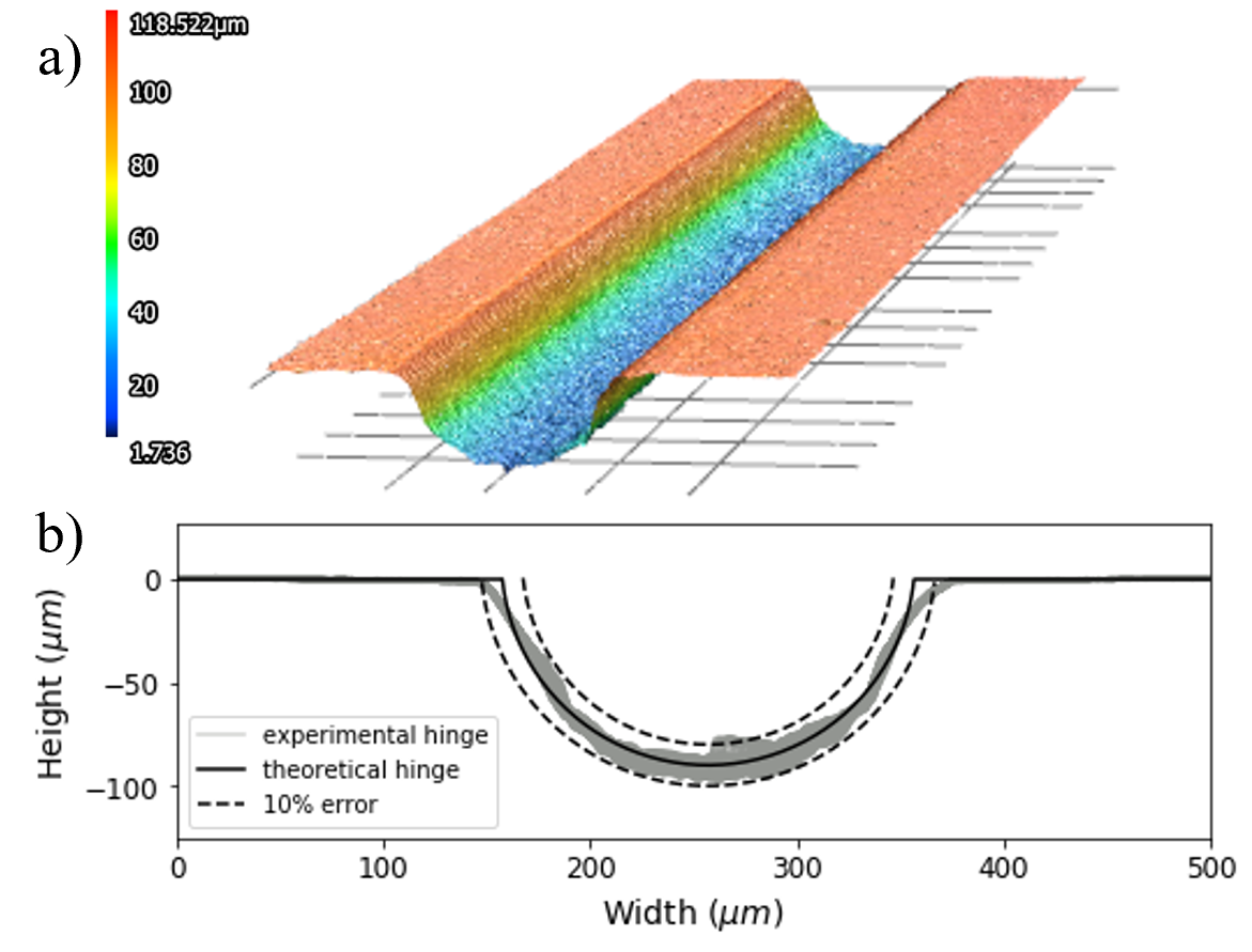
To confirm our characterization results, we fabricated a circular cross-section living hinge (depth of 90 m) with the ideal parameters as determined above using the confocal microscope described previously. Fig. 3b plots the expected cross-section with the manufactured one over the hinge width of 2 mm. This figure shows our ability to create hinges with a tolerance below 10% of the depth of the cut, and, excluding a few outliers, the large majority of the hinge is within m of the designed cut. In Section V, we discuss methods for reducing this tolerance even further using additional laser processing.
III Hinge Design and Characterization
III-A Design
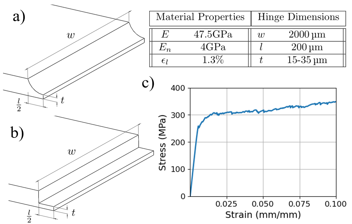
We decided to manufacture and test hinges with two different hinge cross sections of varying thickness: rectangular, shown in Fig. 4a and circular, shown in Fig. 4b. The table in Fig. 4 shows the dimensions and material properties of the hinges. Ease of fabrication and modeling motivated our decision to create rectangular hinges, and the high prevalence of arc-shaped living hinges in existing compliant mechanisms motivated the circular hinges.
III-B Analytical Model from Mechanics Theory
Nitinol’s stress as a function of strain is often described using a ”bilinear” model due to its phase change from austinite to a mixture of austinite and martensite at strains above the critical strain: . Above the elastic modulus of the mixed phase, is lower than the modulus of pure austinite, . We provide the values we used in the table in Fig. 4. We experimentally quantified the stress-strain curve for our material in Fig. 4c. In order to model the hinges with rectangular cross-section, we use the existing model described in York et al., [33]. In this model, we compute the strain energy over the full hinge using stress and strain as a function of the hinge angle. We then use Castigliano’s Theorem to compute the torque of the hinge from strain energy. Fig. 5 shows the results from this model compared to physical torque tests.
III-C Computational Model in Abaqus
While the analytical model above works well for rectangular cross sections, it is difficult to adapt for hinges with arbitrary cross sections. Therefore, we designed a numerical model in Abaqus to determine the torque produced by hinges with arbitrary shapes. We used the experimentally determined bilinear stress-strain relationship as the material model. Fig. 5 shows the results from this model compared to physical torque tests on hinges with both rectangular and circular cross sections. This model will be incredibly useful for designing hinges with more complex cross sections, which is essential for high-performance devices like the wing mechanism discussed in Section IV.
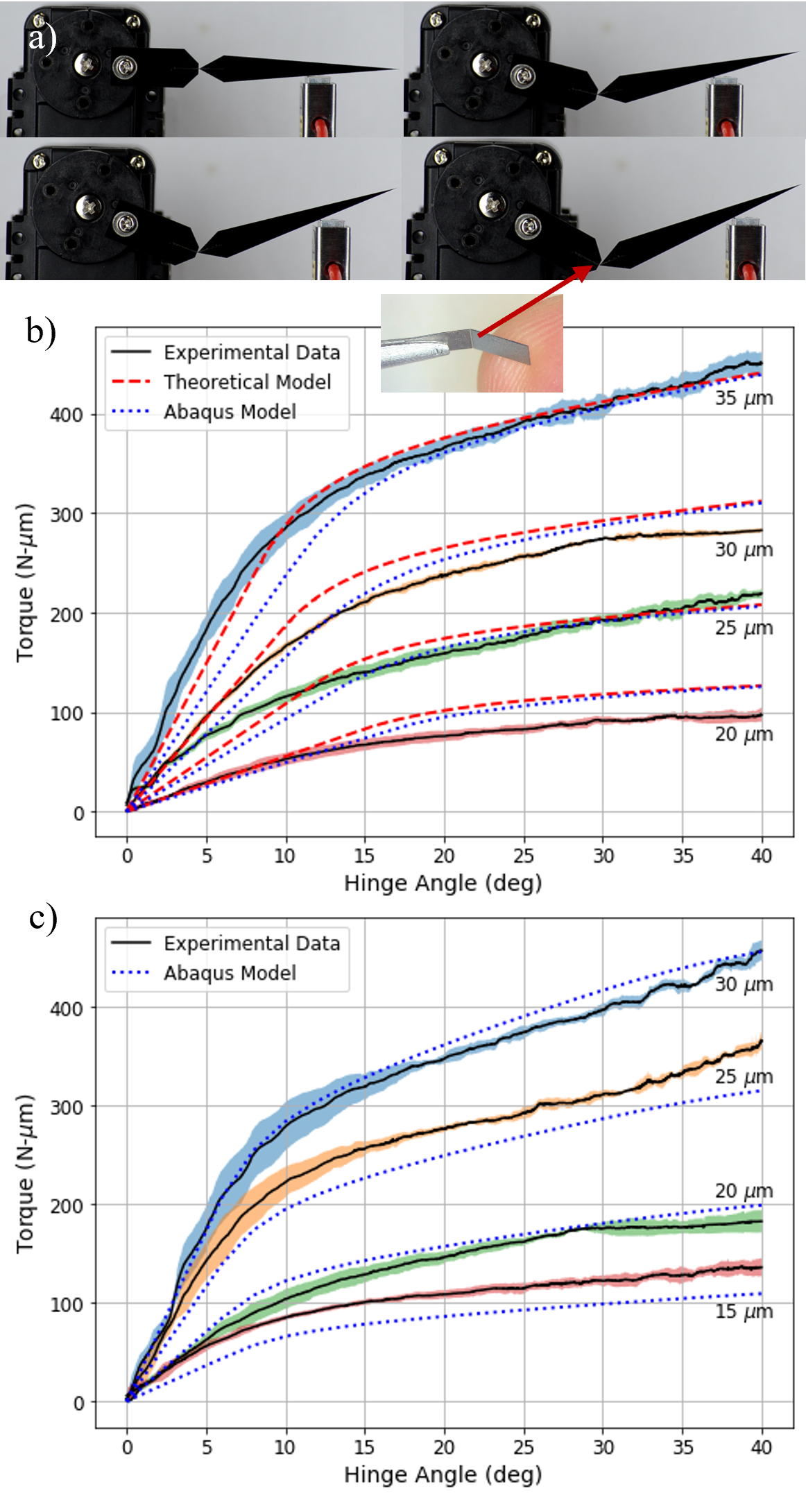
III-D Experimental Characterization
In order to experimentally validate the theoretical and finite element models for our hinges, we performed a quasi-static test measuring the flexure’s torque as a function of angle. The experimental setup, shown in Fig. 5a, includes a servo motor (Dynamixel AX-12A) and a S-Beam type load cell (Futek LSB200) with suitable range for measuring our hinges’ torque. We performed 5 trials each for 4 rectangular hinges with thicknesses 35, 30, 25, 20 m and 4 circular hinges with thicknesses 30, 25, 20, and 15 m, bending each hinge to a 40° angle. We passed the data through a 101 order median filter to smooth the noise and took the average and standard deviation of the 5 trials for each thickness.
Fig. 5b displays the results from the torque experiment for the rectangular hinges and 5c for the circular hinges. These experimentally obtained torque profiles show a good agreement with both the theoretical model and the finite element model predictions. We suspect the differences between the experiment and theory are due to minor manufacturing discrepancies, and we discuss ways to reduce these discrepancies in Section V. Having validated the models successfully, we use them for designing living hinges with specifically tuned torque profiles as dictated by the application needs. We explore one such application, a robotic wing, in the next section.
IV Applications
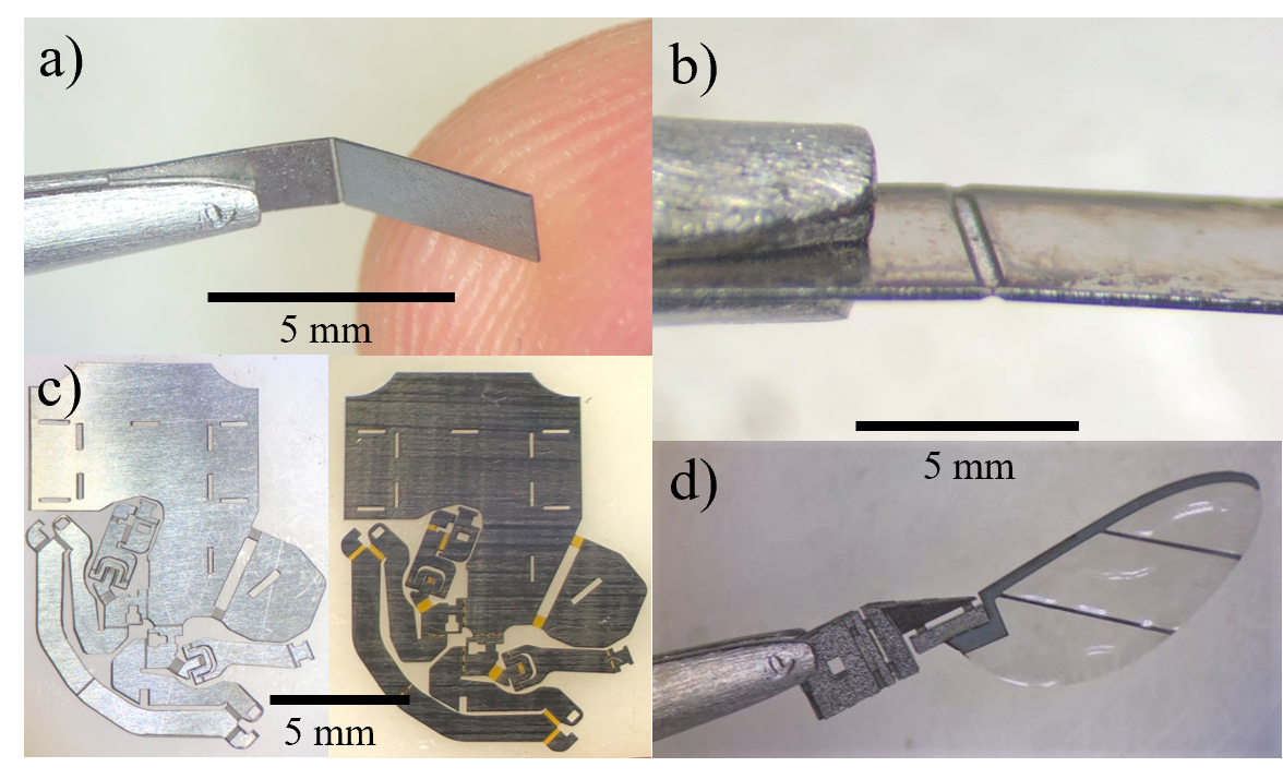
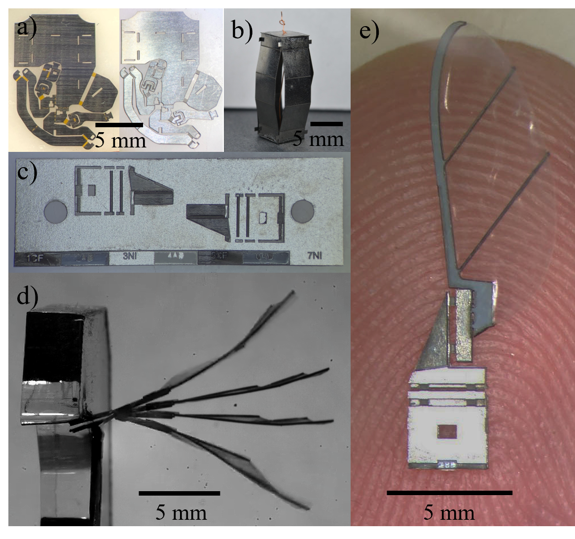
For our first prototype, we made a spherical 5-bar mechanism, originally designed as a 2-DOF leg mechanism for a milli-robot made of carbon fiber and Kapton [14]. Fig. 6a compares the unfolded nitinol mechanism (right) with the carbon fiber and Kapton mechanism (left). The carbon fiber and Kapton mechanism was manufactured using a multilayer laminate laser micromachining process. As stated in the Introduction, this process involves many steps including cutting multiple different layers, heat pressing, release cutting, and folding. However, we manufactured the monolithic nitinol leg using a single cut in the laser, reducing manufacturing time from around 4-5 hours to about 30 minutes. Therefore, using our model to design hinge stiffness, we can obtain appropriate hinge dimensions to develop this design into a legged millirobot. For our second prototype, we made a sarrus linkage, shown in Fig. 6b.
For our final prototype device, we chose to make a 4-bar wing transmission mechanism to illustrate the usefulness of strong, high-displacement hinges for certain milli-robot applications. This design is inspired from the RoboBee wing transmission [42, 43]. However, our design has about half as many layers because nitinol can be used as a structural material as well as a flexural material. The typical operating wing pitch angle for the passive hinge in the mechanism is 50°, past the elastic range of the traditional material used for these hinges: Kapton [44]. However, this angle is within the elastic range for nitinol hinges with a thickness of 22 m or less, assuming a elastic strain limit of 6%. Furthermore, the original mechanism has 15 total layers and 2 different adhesive curing processes. For these reasons, this wing mechanism is ideal for testing our nitinol hinges because we have the potential to greatly increase the mechanism’s lifespan while reducing manufacturing time. Using nitinol as both a flexural and structural material in the wing allowed us to reduce the stack to only 7 layers (2 carbon fiber, 2 nitinol, 3 adhesive) and 1 adhesive curing process.
Fig. 6c shows a stackup of the mechanism’s 7-layer design. We cut these 7 layers separately in the laser and aligned them using vertical alignment pins. Next, we heat-pressed them all together in a single cycle. Finally, we performed a cut on the laser to release the mechanism from its supports. The entire manufacturing process takes about three and a half hours. Fig. 6d shows the manufactured wing mechanism resting on a fingertip. We built a small test fixture to hold the wing transmission in place while we actuated it with a piezo-electric actuator. Fig. 6e shows a composite image of the wing during a test in which we drove the piezo-electric actuator at 200 Hz and 200 V. The wing mechanism reached a peak-to-peak stroke amplitude of 50°, surpassing the elastic range of Kapton. However, since this value is within the elastic range for nitinol, we hypothesize that after optimizing the transmissions, they would have a much longer lifespan and demonstrate superior mechanical performance than transmissions made with Kapton as the flexural material.
V Discussion and Future Work
Accurately manufacturing 2.5D hinge cross-sections with nitinol, while retaining superelastic properties, is essential for nitinol-based applications in micro-robots and medical devices. We have demonstrated that this is possible using femtosecond laser technology. In future projects, we plan to test the fatigue life and elastic deformation of different hinge shapes and thicknesses in order to optimize hinge geometry. These tests will be vital for future applications of these hinges which we will actively actuate and control using piezoelectrics or other milli-device compatible actuation methods. Furthermore, due to the accuracy of the manufacturing process, we will attempt to prototype monolithic 2-DOF flexures. Multi-DOF flexures have the potential to further reduce size, weight, and complexity of future devices.
Finally, we believe we can reduce the tolerance for 2.5D hinge cuts from to below by varying the laser’s attenuation settings. By dialing in exact power settings using the confocal microscope to get even more accurate cut settings, we can slice the hinge with smaller step sizes, allowing for tighter tolerances.
In conclusion, we proposed a new process for manufacturing nitinol living hinges: femtosecond laser machining. We characterized this process in order to accurately manufacture complex 2.5D hinge shapes. We then tested the hinge torque, compared the results to a theoretical model, and built a prototype device. With future supplementary research into optimal hinge cross sections, these versatile hinges will be useful in a wide number of applications across multiple fields of mechanical engineering including microrobotics.
Acknowledgments
The authors would like to thank William McDonnell for his assistance with the various test setups and Brandon Hayes for help obtaining the confocal microscope images.
References
- [1] K. Jayaram and R. J. Full, “Cockroaches traverse crevices, crawl rapidly in confined spaces, and inspire a soft, legged robot,” Proceedings of the National Academy of Sciences, vol. 113, no. 8, 2016.
- [2] S. D. De Rivaz, B. Goldberg, N. Doshi, K. Jayaram, J. Zhou, and R. J. Wood, “Inverted and vertical climbing of a quadrupedal microrobot using electroadhesion,” Science Robotics, vol. 3, no. 25, 2018.
- [3] W. Hu, G. Z. Lum, M. Mastrangeli, and M. Sitti, “Small-scale soft-bodied robot with multimodal locomotion,” Nature, vol. 554, no. 7690, pp. 81–85, 2018.
- [4] B. J. Nelson, I. K. Kaliakatsos, and J. J. Abbott, “Microrobots for minimally invasive medicine,” Annual review of biomedical engineering, vol. 12, pp. 55–85, 2010.
- [5] T. Wallin, J. Pikul, and R. F. Shepherd, “3d printing of soft robotic systems,” Nature Reviews Materials, vol. 3, no. 6, pp. 84–100, 2018.
- [6] K.-J. Cho, J.-S. Koh, S. Kim, W.-S. Chu, Y. Hong, and S.-H. Ahn, “Review of manufacturing processes for soft biomimetic robots,” International Journal of Precision Engineering and Manufacturing, vol. 10, pp. 171–181, 2009.
- [7] R. J. Wood, S. Avadhanula, R. Sahai, E. Steltz, and R. S. Fearing, “Microrobot design using fiber reinforced composites,” 2008.
- [8] P. S. Sreetharan, J. P. Whitney, M. D. Strauss, and R. J. Wood, “Monolithic fabrication of millimeter-scale machines,” Journal of Micromechanics and Microengineering, vol. 22, no. 5, 2012.
- [9] N. Doshi, K. Jayaram, S. Castellanos, S. Kuindersma, and R. J. Wood, “Effective locomotion at multiple stride frequencies using proprioceptive feedback on a legged microrobot,” Bioinspiration & biomimetics, vol. 14, no. 5, 2019.
- [10] D. Yu and F. Spaepen, “The yield strength of thin copper films on kapton,” Journal of Applied Physics - J APPL PHYS, vol. 95, 03 2004.
- [11] S. Kim, Y.-H. Hsiao, Y. Lee, W. Zhu, Z. Ren, F. Niroui, and Y. Chen, “Laser-assisted failure recovery for dielectric elastomer actuators in aerial robots,” Science Robotics, vol. 8, no. 76, Mar. 2023, publisher: American Association for the Advancement of Science.
- [12] G.-Z. Yang, J. Bellingham, P. E. Dupont, P. Fischer, L. Floridi, R. Full, N. Jacobstein, V. Kumar, M. McNutt, R. Merrifield, et al., “The grand challenges of science robotics,” Science robotics, vol. 3, no. 14, 2018.
- [13] D. Zhang, T. E. Gorochowski, L. Marucci, H.-T. Lee, B. Gil, B. Li, S. Hauert, and E. Yeatman, “Advanced medical micro-robotics for early diagnosis and therapeutic interventions,” Frontiers in Robotics and AI, vol. 9, 2023.
- [14] H. Kabutz and K. Jayaram, “Design of clari: A miniature modular origami passive shape-morphing robot,” Advanced Intelligent Systems, 2023.
- [15] H. Kabutz, A. Hedrick, P. McDonnell, and K. Jayaram, “mclari: a shape-morphing insect-scale robot capable of omnidirectional terrain-adaptive locomotion in laterally confined spaces,” arXiv preprint arXiv:2310.04538, 2023.
- [16] S. Palagi and P. Fischer, “Bioinspired microrobots,” Nature Reviews Materials, vol. 3, no. 6, pp. 113–124, 2018.
- [17] F. Soto, E. Karshalev, F. Zhang, B. Esteban Fernandez de Avila, A. Nourhani, and J. Wang, “Smart materials for microrobots,” Chemical Reviews, vol. 122, no. 5, pp. 5365–5403, 2021.
- [18] D. Stöckel, “Nitinol - A material with unusual properties.”
- [19] T. Duerig, A. Pelton, and D. Stöckel, “An overview of nitinol medical applications,” Materials Science and Engineering: A, vol. 273-275, pp. 149–160, Dec. 1999.
- [20] X. Yang, L. Chang, and N. O. Pérez-Arancibia, “An 88-milligram insect-scale autonomous crawling robot driven by a catalytic artificial muscle,” Science Robotics, vol. 5, no. 45, Aug. 2020, publisher: American Association for the Advancement of Science.
- [21] P. A. York, R. Peña, D. Kent, and R. J. Wood, “Microrobotic laser steering for minimally invasive surgery,” Science Robotics, vol. 6, no. 50, Jan. 2021, publisher: American Association for the Advancement of Science.
- [22] R. Chaudhari, J. J. Vora, and D. M. Parikh, “A Review on Applications of Nitinol Shape Memory Alloy,” in Recent Advances in Mechanical Infrastructure, ser. Lecture Notes in Intelligent Transportation and Infrastructure, A. K. Parwani, P. Ramkumar, K. Abhishek, and S. K. Yadav, Eds. Singapore: Springer, 2021, pp. 123–132.
- [23] M. Mertmann, “Non‐medical applications of NiTinol,” Minimally Invasive Therapy & Allied Technologies, vol. 13, no. 4, pp. 254–260, Jan. 2004.
- [24] K. Jayaram, J. Shum, S. Castellanos, E. F. Helbling, and R. J. Wood, “Scaling down an insect-size microrobot, hamr-vi into hamr-jr,” in 2020 IEEE International Conference on Robotics and Automation (ICRA). IEEE, 2020, pp. 10 305–10 311.
- [25] J. Liu, B. Hall, M. Frecker, and E. W. Reutzel, “Compliant articulation structure using superelastic nitinol,” Smart materials and structures, vol. 22, no. 9, 2013.
- [26] C. Haberland, M. Elahinia, J. Walker, and H. Meier, “Visions, concepts and strategies for smart nitinol actuators and complex nitinol structures produced by additive manufacturing,” in Smart Materials, Adaptive Structures and Intelligent Systems, vol. 56031. American Society of Mechanical Engineers, 2013.
- [27] M. Mertmann and G. Vergani, “Design and application of shape memory actuators,” The European Physical Journal Special Topics, vol. 158, no. 1, pp. 221–230, 2008.
- [28] G. Costanza, M. Tata, and C. Calisti, “Nitinol one-way shape memory springs: Thermomechanical characterization and actuator design,” Sensors and Actuators A: Physical, vol. 157, no. 1, pp. 113–117, 2010.
- [29] A. Srivastava, R. Xu, A. Escoto, C. Ward, and R. V. Patel, “Design of an ultra thin strain sensor using superelastic nitinol for applications in minimally invasive surgery,” in 2016 IEEE International Conference on Advanced Intelligent Mechatronics (AIM). IEEE, 2016, pp. 794–799.
- [30] D. J. S. Ruth, “Design concepts for nitinol wires to function as a sensor,” Transactions of the Indian National Academy of Engineering, vol. 6, no. 2, pp. 523–531, 2021.
- [31] D. Hodgson and S. Russell, “Nitinol melting, manufacture and fabrication,” Minimally Invasive Therapy & Allied Technologies, vol. 9, no. 2, pp. 61–65, Jan. 2000, publisher: Taylor & Francis _eprint: https://doi.org/10.3109/13645700009063051.
- [32] J. W. Mwangi, L. T. Nguyen, V. D. Bui, T. Berger, H. Zeidler, and A. Schubert, “Nitinol manufacturing and micromachining: A review of processes and their suitability in processing medical-grade nitinol,” Journal of Manufacturing Processes, vol. 38, pp. 355–369, Feb. 2019.
- [33] P. A. York and R. J. Wood, “Nitinol living hinges for millimeter-sized robots and medical devices,” in 2019 International Conference on Robotics and Automation (ICRA), May 2019, pp. 889–893, iSSN: 2577-087X.
- [34] M. J. Mahtabi, N. Shamsaei, and M. R. Mitchell, “Fatigue of Nitinol: The state-of-the-art and ongoing challenges,” Journal of the Mechanical Behavior of Biomedical Materials, vol. 50, pp. 228–254, Oct. 2015.
- [35] N. Uppal and P. S. Shiakolas, “Micromachining Characteristics of NiTi Based Shape Memory Alloy Using Femtosecond Laser,” Journal of Manufacturing Science and Engineering, vol. 130, no. 3, June 2008.
- [36] H. Huang, H. Y. Zheng, and G. C. Lim, “Femtosecond laser machining characteristics of Nitinol,” Applied Surface Science, vol. 228, no. 1, pp. 201–206, Apr. 2004.
- [37] M. J. Pfeifenberger, M. Mangang, S. Wurster, J. Reiser, A. Hohenwarter, W. Pfleging, D. Kiener, and R. Pippan, “The use of femtosecond laser ablation as a novel tool for rapid micro-mechanical sample preparation,” Materials & Design, vol. 121, pp. 109–118, 2017.
- [38] J. B. Hopkins, “Design of parallel flexure systems via freedom and constraint topologies (fact),” Ph.D. dissertation, Massachusetts Institute of Technology, 2007.
- [39] L. A. Shaw, F. Sun, C. M. Portela, R. I. Barranco, J. R. Greer, and J. B. Hopkins, “Computationally efficient design of directionally compliant metamaterials,” Nature communications, vol. 10, no. 1, p. 291, 2019.
- [40] B. McCarthy, E. Nail, A. Nagarajan, J. McCullough, and J. B. Hopkins, “Design of configuration indifferent compliant building blocks,” Precision Engineering, 2023.
- [41] B. Hayes, L. Smith, H. Kabutz, A. C. Hayes, G. L. Whiting, K. Jayaram, and R. MacCurdy, “Rapid fabrication of low-cost thermal bubble-driven micro-pumps,” Micromachines, vol. 13, no. 10, p. 1634, 2022.
- [42] R. Wood, “Design, fabrication, and analysis of a 3DOF, 3cm flapping-wing MAV,” in 2007 IEEE/RSJ International Conference on Intelligent Robots and Systems, Oct. 2007, pp. 1576–1581, iSSN: 2153-0866.
- [43] W. Salem, B. Cellini, H. Kabutz, H. K. Hari Prasad, B. Cheng, K. Jayaram, and J.-M. Mongeau, “Flies trade off stability and performance via adaptive compensation to wing damage,” Science Advances, vol. 8, no. 46, 2022.
- [44] N. Gravish and R. J. Wood, “Anomalous yaw torque generation from passively pitching wings,” in 2016 IEEE International Conference on Robotics and Automation (ICRA), May 2016, pp. 3282–3287.