Ultrafast Optical Modulation by Virtual Interband Transitions.
Abstract
A new frontier in optics research has been opened by the recent developments in non-perturbative optical modulation in both time and space that creates temporal boundaries generating “time-reflection” and “time-refraction” of light in the medium. The resulting formation of a Photonic Time Crystal within the modulated optical material leads to a broad range new phenomena with a potential for practical applications, from non-resonant light amplification and tunable lasing, to the new regime of quantum light-matter interactions. However, the formation of the temporal boundary for light relies on optical modulation of the refractive index that is both strong and fast even on the time scale of a single optical cycle. Both of these two problems are extremely challenging even when addressed independently, leading to conflicting requirements for all existing methods of optical modulation. However, as we show in the present work, an alternative approach based on virtual interband transition excitation, solves this seemingly insurmountable problem. Being fundamentally dissipation-free, optical modulation by virtual excitation does not face the problem of heat accumulation and dissipation in the material, while the transient nature of the excited virtual population that modifies the material response only on the time scale of a single optical cycle, ensures that the resulting change in the refractive index is inherently ultrafast. Here we develop the theoretical description of the proposed modulation approach, and demonstrate that it can be readily implemented using already existing optical materials and technology.
I Introduction
A large change in the refractive index of an optical material generally relies on introducing a substantial change in the energies of its electrons, whether bound or free.BornWolf ; Boyd ; Khurgin-index While this can be achieved in many different ways, from mechanical strain strain and acousto-optics acousto-optics to thermal effects thermal to carrier density modulation, electrooptics it is generally followed by the relatively slow dissipation (or recycling) of the resulting increase of the energy density (on the order of J/cm3).Khurgin-index The corresponding relaxation times (such as e.g. heat diffusion time, electron-hole recombination time, hot carrier recombination time, etc.) generally exceed sub-picosecond time scale, Khurgin-index and do not enter the few femtoseconds range necessary for the formation of an optical Photonic Time Crystal.PTC1 ; PTC2 ; VSMotiR1 ; VSMotiR2 This situation is however dramatically reversed when free carriers undergo virtual interband transitions, induced by a strong optical pump pulse at the frequency just below the interband absorption range of the material, with only a few optical cycles in its duration . While having insufficient energy to allow for a real transition of a free carrier to another band, the inherent energy uncertainty in the pump photons,
| (1) |
may provide the required “excess energy” to promote the interband transition and ensure the formation of virtual populations, that necessarily modify the refractive index of the material. Note that this is an inherently transient response, as such virtual populations are only manifest in the presence of the pump pulse – leading to nearly-instantaneous “turn-on” and “turn-off” of the refractive index modulation.
As virtual transitions are generally dissipation-free,LLQM the proposed approach is free from the energy dissipation/recycling bottleneck, that limits the electromagnetic energy density used to change the dielectric permittivity of the material and thus magnitude of refractive index variation in the conventional methods.Khurgin-index Without the need to allow for the slow relaxation of the refractive index, it can be periodically modulated with the period that is comparable to that of a single optical pump pulse duration – which therefore offers a clear and immediate solution of the problem of ultrahigh frequency periodic modulation of the refractive index, that in necessary for the band formation in the elusive optical Photonic Time Crystal.VSMotiR1
II The Concept
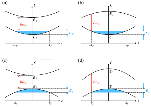
The proposed approach to ultrafast optical modulation only relies on the presence of a sufficient number of free carriers in either the conduction or valence band of the optical material, and it equally applicable to all band topologies (see Fig. 1). While it may be advantageous to choose the operating frequency above the free carrier plasma frequency (to ensure relative transparency of the material) or close to (for the operation in the epsilon-near-zero regime when a given absolute variation in the refractive index turns into a higher relative change), these are neither essential nor necessarily advantageous for the implementation of the present concept of ultrafast refractive index modulation.
In the proposed approach, the material is optically pumped with the ultra-short pulse (of duration that is on the order of few of its optical cycles) at the frequency below the interband absorption edge (see Fig. 1), with
| (2) |
In this regime, the pump photon energy uncertainty is comparable to the energy difference between the band offset and the pump photon energy , leading to a substantial virtual carrier population formation in different bands. This excited carrier population is inherently transient, and can only exist for no longer that few optical cycles, while the pump pulse is present. The pump-induced virtual populations are therefore only manifest for the duration of the ultra-short pump pulse, regardless of the mechanism of the band-to-band relaxation/recombination in the materials and its corresponding time scale . This inherently ultrafast and dissipation-free nature of the virtual interband transitions – the capability that’s essential for formation of the photonic time crystals VSMotiR1 – is an essential feature of the proposed refractive index modulation approach.
The proposed concept of the strong modulation of the dielectric permittivity due to the formation of transient populations, relies on the material response where virtual carriers contribute to the electromagnetic response of the medium in essentially the same manner as real electrons (albeit without relaxation). While possibly counter-intuitive, this behavior has been firmly established for nearly half a century, since it was discovered in mid-1980s in the ultrashort pulse generation experiments with GaAs quantum wells, where intense optical interaction below the optical absorption threshold induced substantial virtual populations with measurable consequences.Yamanishi-PRL-1987 , In particular, measurements of ac Stark effect in GaAs quantum wells showed clear evidence of unharmonic interactions of virtually created electrons and holes.Mysyrowicz-PRL-1986 ,VLCZH-OL-1986 Furthermore, the resulting screening of the virtual carrier populations was essential for the generation of ultrashort electrical pulses in biased quantum wells.CMSR-PRL-1987 This well established experimental evidence firmly justifies the proposed mechanism where the virtual carriers respond to the electromagnetic field as if they are real electrons and holes, leading to the strong and fast modulation of the dielectric permittivity.
Furthermore, it has also been demonstrated that while virtual carrier populations produce exactly the same physical effect as the real ones, they do not participate in any relaxation process SRC-PRL-1986 – which is the key for our proposed ultrafast modulation scheme.
III The Model
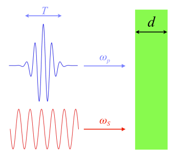
We consider a parallel slab of an optical material that is simultaneously illuminated with with a high-intensity “pump” pulse at the central frequency with only a few optical cycles in its duration , while the signal at the frequency operates in the linear response regime – see Fig. 2. The material supports a sizable free-carrier population, characterized by the corresponding plasma frequency that is comparable to (see Fig. 2) but is well below the pump frequency , that is in turn below interband absorption edge (indicated in Fig. 1 for various band topologies):
| (3) |
With the same order of magnitude for the operating frequency and the free carrier plasma frequency , a noticeable material absorption is unavoidable, which precludes the use of optically thick materials. We therefore assume the regime of subwavelength thickness of the optical material,
| (4) |
which allows to neglect the retardation within the modulated material for both the “pump” and the “probe” .
IV The Theory
For the free carriers in the optical material subject to both pump and probe/signal fields, the corresponding von Neumann density function equations Boyd take the form
| (5) | |||||
where is the free-electron density matrix operator with the equilibrium value , is the matrix of the corresponding (phenomenological) relaxation coefficients, and are the free electron band index and Bloch momentum, while and are the effective Hamiltonians of electron interaction with the (time-dependent) “pump” and “signal” electromagnetic fields.
Note that, even within the assumptions of Eqn. (4), one may still be tempted to “fully” account for the electromagnetic field spatial variation in the direction of propagation within the optical material (where is the electromagnetic wavenumber), leading to the corresponding spatial dispersion corrections in the resulting theory.LLECM However, from plasmonic metals ( is the UV range SCai ) to transparent conducting oxides ( in near-infrared TCOs ) to highly doped semiconductors ( in mid-IR nmat ), the free carrier mean free path does not exceed a small fraction of the operating optical wavelength. Therefore, on the scale of the free electron wavefunctions in the scattering environment, the acting field in the matrix element for electronic interband transitions should be treated as uniform, leading to the selection rule for the “vertical” interband transitions , for ,
| (6) |
Here is the effective Hamiltonian of light-matter interactions for the (time-dependent) “pump field”
| (7) |
is the (Kronecker’s) delta-function, is the unit vector that represents the field polarization, and the interband matrix element
| (8) |
where is the band index, is the free carrier Bloch wavefunction, and is the volume of the material unit cell.
On the other hand, for the corresponding intra-band () matrix element, the free-carrier Bloch functions can be adequately approximated by their values at the band energy extremum,Ziman leading to
| (9) |
As the amplitude of the “signal” is small to ensure the linear-response regime operation, and the corresponding frequency is well below the inter-band absorption edge ( – see Eqn. (2)), the solution of (5) in terms of can be obtained using the standard perturbative approach,Boyd leading to the effective dielectric permittivity
| (10) | |||||
where is the free carrier effective mass in the band , is the free carrier relaxation rate averaged over the volume of the Fermi surface of the conduction band, and the transient population density is defined in terms of the diagonal elements of density matrix of the free carriers strongly coupled to the pump pulse
| (11) |
where with “vertical transition” selection rule of Eqn. (6) the reduced density matrix satisfies the (infinite) system of coupled nonlinear differential equations
| (12) | |||||
with the effective dipole matrix element again defined in terms of the reciprocal space average over the volume of the Fermi surface of the conduction band.
The requirement of strong coupling between the optical pump pulse and the free carriers in the material,
| (13) |
can be only satisfied for a single pair of electronic bands (which will be represented by the indices and , for the occupied and unoccupied bands respectively – see Fig. 1), which allows to neglect all other interband transitions in Eqn. (12). The system (12) then effectively separates into a set of uncoupled pairs of equations for and the “population inversion” :
| (14) | |||||
| (15) |
where and are the electronic band edge energies (see Fig. 2), the (-dependent) detuning factor
| (16) |
and we’ve used the standard notation Boyd for the population relaxation time and the dephasing time .
In the limit of (2) which is the focus of the present work, Eqns. (14),(15) can be solved analytically, which for thermal energy well below and yields
| (17) | |||||
where is the optical pump intensity, and . Substituting
| (18) | |||||
| (19) |
into (11), for we obtain
| (20) |
where is the virtual induced population
| (21) |
and
| (22) |
Here is the equilibirum free carrier density, and
| (23) |
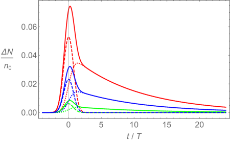
As expected, the virtual transitions lead to the formation of the transient population for the duration of the optical pump pulse, while the multi-photon absorption yields the “real” population change that persists for a much longer duration defined by the relaxation time . This behavior is illustrated in Fig. 3.
For the dielectric permittivity at the signal frequency we then obtain
| (24) |
where is the background permittivity due to the contributions of the bound electrons in the material, the effective time-dependent plasma frequency
| (25) |
where is the original plasma frequency in the medium before the activation of the optical pump, and the effective loss rate
| (26) |
Here, the contribution represents the relative change of the plasma frequency due to the formation of the virtual carrier population in the high-energy band at the expense of the carrier density in the conduction band for the duration of the optical pump . As expected, the modulation of the effective plasma frequency due to is only present on the time scale of the optical pump pulse . In contrast to this behavior, “real” population change accounted for by that is induced by the multi-photon absorption in the medium, persists for the duration of subsequent carrier relaxation time . We find
| (27) |
and
| (28) | |||||
while
| (29) | |||||
Note that the signs of and depend on the difference between the free carrier effective masses in the bands.
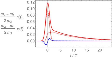
In Fig. 4, we show the time dependence of the relative changes in the effective plasma frequency and in the effective loss rate. Note the expected two-stage evolution in both of these parameters – a rapid change for the duration of the pump pulse due to the virtual interband transitions, followed by effect of multi-photon absorption that persist on the time scale of the interband relaxation time .
V Ultrafast virtual modulation in transparent conducting oxides
With the plasma frequency in the near-infrared, and absorption edge at the higher frequency end or even beyond the visible range,TCOs transparent conducting oxides offer a convenient platform for the implementation of the proposed approach to ultrafast optical modulation by virtual interband transitions. In particular, for the indium-tin oxide (ITO) the absorption edge corresponds to the blue portion of the visible spectrum, while the plasma frequency is in the infrared range.ITO The necessary requirements for the implementation of our approach (3) can therefore be satisfied with the use of a few-cycle pump pulse at lower visible frequencies and the signal in the near-infrared range.
As the bandstructure of the ITO Julia corresponds to the case (b) of Fig. 1, with the effective masses and Eqns. (24)-(28) imply that the the dielectric permittivity of the ITO will increase with the arrival of the optical pump pulse, and decrease at its departure. If another optical signal is simultaneously propagating in the modulated material (see Fig. 2), it will then experience red frequency shift when the permittivity goes up, and blue shift when it goes down.
This physical mechanism explains the origin of such behavior recently found in the experiments of Ref. VSMoti , where ITO thin film was simultaneously illuminated by high-intensity femtosecond pulses at the (central) wavelength of 800 nm, and slowly varying “probe” beam at nm wavelength – leading to the observation of red frequency shift immediately followed by the blue frequency shift. As the experimental parameters in Ref. VSMoti are well within the constraints of the inequality (3), that work should be considered as the world’s first experimental implementation of the proposed ultrafast optical modulation by virtual interband transitions.
We however emphasize, that our approach is not in any way special to ITO or even to the whole group of transparent conducting oxides, but with the proper choice of experimentally controlled parameters (optical pump pulse duration and central frequency , and the signal frequency ) it can be applied to any optical material supporting free carriers.
VI Conclusions
We have introduced a new approach to ultrafast optical modulation, based on the virtual interband transition excitation. Being inherently ultrafast and relaxation-free, it offers a direct and practical way to create “temporal boundaries” for light, in already existing materials and with a straightforward implementation using only the standard toolbox of modern ultra-fast optics – thus finally opening the route to the elusive Photonic Time Crystal at optical frequencies.
VII Acknowledgements
The author would like to thank Profs. Sasha Boltasseva and Vlad Shalaev for helpful discussions.
References
- (1) M. Born and E. Wolf, Principles of Optics: Electromagnetic Theory of Propagation, Interference and Diffraction of Light, 7th ed. (Cambridge, Cambridge University Press, 1999).
- (2) R. Boyd, Nonlinear Optics (Academic Press; 2nd edition, 2002).
- (3) J. B. Khurgin, “Energy and Power requirements for alteration of the refractive index,” preprint arXiv:2308.16011 (2023).
- (4) C. E. Campanella, A. Cuccovillo, C. Campanella, A. Yurt, and V. M. Passaro, “Fibre Bragg grating based strain sensors: Review of technology and applications,” Sensors 18, 3115 (2018).
- (5) A. Korpel, “Acousto-optics?a review of fundamentals,” Proceedings of the IEEE 69, 48 - 53 (1981).
- (6) J. Komma, C. Schwarz, G. Hofmann, D. Heinert, and R. Nawrodt, ”Thermo-optic coefficient of silicon at 1550 nm and cryogenic temperatures,” Applied Physics Letters 101, 041905 (2012).
- (7) R. Soref and B. Bennett, “Electrooptical effects in silicon,” IEEE Journal of Quantum Electronics 23, 123 - 129 (1987).
- (8) J. R. Zurita-Sánchez, J. H. Abundis-Patiño, and P. Halevi, “Pulse propagation through a slab with time-periodic dielectric function ,” Opt. Express 20, 5586 - 5600 (2012).
- (9) E. Lustig, Y. Sharabi, and M. Segev,“Topological aspects of photonic time crystals,” Optica 5, 1390 (2018).
- (10) E. Lustig, O. Segal, S. Saha, C. Fruhling, V. M. Shalaev, A. Boltasseva, and M. Segev, “Photonic time-crystals - fundamental concepts,” Opt. Express 31, 9165 - 9170 (2023).
- (11) S. Saha, O. Segal, C. Fruhling, E. Lustig, M. Segev, A. Boltasseva, and V. M. Shalaev, “Photonic time crystals: a materials perspective,” Opt. Express 31, 8267 - 8273 (2023).
- (12) L. D. Landau and L. M. Lifshitz, Quantum Mechanics, (Butterworth-Heinemann; 3rd edition, 1981).
- (13) L. D. Landau, L. P. Pitaevskii, and E. M. Lifshitz, Electrodynamics of Continuous Media (Butterworth-Heinemann; 2nd edition, 1984).
- (14) W. Cai and V. Shalaev, Optical metamaterials: fundamentals and applications (Springer Science & Business Media, 2009).
- (15) W. Jaffray, S. Saha, V. M. Shalaev, A. Boltasseva, and M. Ferrera, “Transparent conducting oxides: from all-dielectric plasmonics to a new paradigm in integrated photonics,” Advances in Optics and Photonics 14 (2), 148 - 208 (2022).
- (16) A. J. Hoffman, L. Alekseyev, S. S. Howard, K. J. Franz, D. M. Wasserman, V. A. Podolskiy, E. E. Narimanov, D. L. Sivco, C. Gmachl, ”Negative refraction in semiconductor metamaterials,” Nature Materials 6, 948 (2007).
- (17) M. Yamanishi, “Field-Induced Nonlinearity Due to Virtual Transitions in Semiconductor Quantum-Well Structures,” Phys. Rev. Lett. 59 (9), 1014 - 1017 (1987).
- (18) S. Schmitt-Rink and D. S. Chemla, “Collective Excitations and the Dynamical Stark Effect in a Coherently Driven Exciton System,” Phys. Rev Lett. 57, 2752 (1986).
- (19) D. S. Chemla, D. A. B. Miller, and S. Schmitt-Rink, “Generation of Ultrashort Electrical Pulses through Screening by Virtual Populations in Biased Quantum Wells,” Phys. Rev Lett. 59, 1018 (1987).
- (20) A. Mysyrowicz, D. Hulin, A. Antonetti, A. Migus, W. T. Masselink, and H. Morkoc, “Dressed Excitons” in a Multiple-Quantum-Well Structure: Evidence for an Optical Stark Effect with Femtosecond Response Time,” Phys. Rev. Lett. 56, 2748 (1986).
- (21) A. Von Lehmen, D. S. Chemla, J. E. Zucker, and J. P. Heritage “Optical Stark effect on excitons in GaAs quantum wells,” Opt. Lett. 11 (10), 609 - 611 (1986).
- (22) J. M. Ziman, “Electrons and Phonons: The Theory of Transport Phenomena in Solids,” Oxford University Press, Reprint edition, 2001.
- (23) A. Sihvola, S. Saastamoinen and K. Heiska, Remote Sensing Reviews 9, 35 (1994).
- (24) J.E. Medvedeva, “Magnetically Mediated Transparent Conductors: In2O3 doped with Molybdenum,” Phys. Rev. Lett. 97, 086401 (2006).
- (25) T. S. Kim, C. H. Choi, T. S. Jeong and K. H. Shim, “Influence of Substrate Temperature and O2 Flow on the Properties of RF-Magnetron-Sputtered Indium-Tin-Oxide Thin Films,” Journal of the Korean Physical Society 51 (2), 534 - 538 (2007).
- (26) E. Lustig, O. Segal, S. Saha, E. Bordo, S. N. Chowdhury, Y. Sharabi , A. Fleischer , A. Boltasseva, O. Cohen , V. M. Shalaev and M. Segev, “Time-refraction optics with single cycle modulation,” Nanophotonics 12 (12), 2221 - 2230 (2023).