Indoor Geometry Generator (IGG)
Abstract
The Indoor Geometry Generator (IGG) is able to generate automatically simplified indoor geometry and its associated unstructured mesh for Computational Fluid Dynamics (CFD) simulations purposes given very simple user inputs. A large number of indoor features are supported by IGG such as (non-exhaustive list): shelves, tills, tables, chairs, seats… Smaller features such as laptops, computer towers and screens can also be included. In addition, doors/windows as well as ventilation inlet and outlet can be taken into account. Finally, the adding of simplified shape of humans standing, sitting or lying are also supported by IGG. IGG allows the user to generate without much effort indoor geometries such that shop, train, bus, plane, school, open spaces…, while being fully consistent with CFD requirements. The geometry and the mesh are outputted in GMSH format supported by both Fluidity and IC-FERST open-source finite-element CFD software.
Chapter 1 Generalities
1.1 Brief description
The Indoor Geometry Generator (IGG) is able to generate automatically simplified indoor geometry and its associated unstructured mesh for Computational Fluid Dynamics (CFD) simulations purposes given very simple user inputs. IGG supports a large number of features allowing the user to generate without much effort indoor geometries such that supermarket, train, bus, plane, school, open spaces…, while being fully consistent with CFD requirements. The geometry and the mesh are outputted in GMSH format supported by both Fluidity and IC-FERST open-source finite-element CFD software [1]. IGG is designed such that different IDs are assigned to different surfaces to allow the user to specify various boundary conditions if wanted such as thermal fluxes for example.
1.2 Getting and running IGG
IGG is available on GitHub under request, just send an email to Dr Laetitia Mottet - laetitia.mottet@gmail.com. Python3, shapely, numpy, descartes, Fluidity (or IC-FERST) and GMSH need to be installed on the machine as detailed in the following sections. Fluidity is (in some cases) optional if the tool checkmesh is not used.
1.2.1 External libraries and software
IGG is written in python v3 - it is therefore required to have python3 install on your machine. In addition, the three following python libraries are needed:
-
•
numpy mathematical library
-
•
shapely manipulation and analysis of geometric objects
-
•
descartes plot using matplotlib of shapely objects (for debug mode in IGG)
To install them using pip:
In addition, it is assumed that the CFD software Fluidity as well as the mesh generator GMSH are installed.
-
•
Fluidity an open-source finite-element mesh-adaptive CFD software available at
https://github.com/FluidityProject/fluidity -
•
GMSH an open source 3D finite element mesh generator available at gmsh.info/
To install them use:
Remark about GMSH versions: It is highly recommended to use GMSH v3.x to enjoy all the capabilities of IGG, especially concerning the mesh refinement and more particularly the sphere and box options (see Section 6) which are only supported from GMSH v3.x and higher. GMSH v2.x will work but the mesh refinement constraint specified by the user will be ignored (see Section 6 and Section 2.6). GMSH v4.x will also work (the mesh will be well outputted), however the migration of Fluidity to GMSH v4.x is not completed yet (at the time of the manual is written!), hence it is not recommended to use it neither.
To test if all the dependencies are correctly installed, in the folder IGG/code/, the user can run:
1.2.2 Running IGG
The main code is IGG.py and the functions are in the src/ forder. To use IGG from anywhere in your machine without copy/paste the code all the time, it is recommended to add an alias in your /.bashrc:
The following 6 input files need to be in the folder the user wants to work in:
-
1.
IGG_Numerics.dat
-
2.
IGG_Domain.dat
-
3.
IGG_Furniture.dat
-
4.
IGG_Accessories.dat
-
5.
IGG_Humans.dat
-
6.
IGG_Mesh.dat
Examples of the input files can be found in the folder examples/. In addition, they are detailed in Section 2.
Finally, in a terminal, where the input files are located - here for example MyFolder/ -, assuming the alias has been added into /.bashrc, run the command IGG:
1.3 Geometry and convention
In this document and in IGG more generally, the word “feature” is used to refer to furniture, accessories, windows, doors, inlet and outlet of ventilation.
The features into IGG can be either 2D or 3D:
-
•
2D features are planar rectangles (ex: inlet and outlet of ventilation, windows…);
-
•
3D features are a compound of one or several rectangular boxes (ex: shelf, chair…).
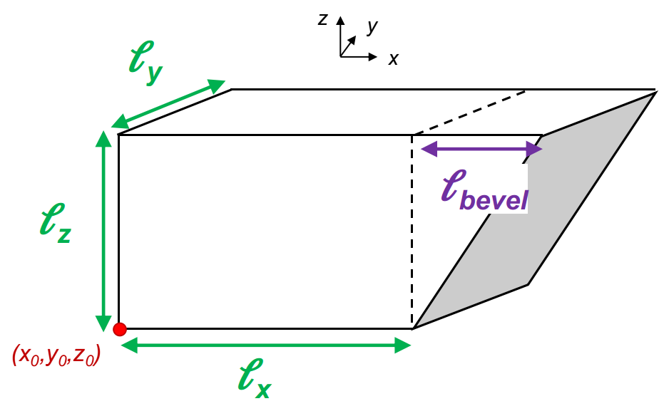
All 3D features are a compound of one or several rectangular boxes, with the exception of “Bevel” which has one of its surface with an inclination that meets the other surfaces at any angle but 90°(see Section 4.2.11 for more details). Moreover, humans are 3D feature made by rectangular boxes and one bevel for the nose.
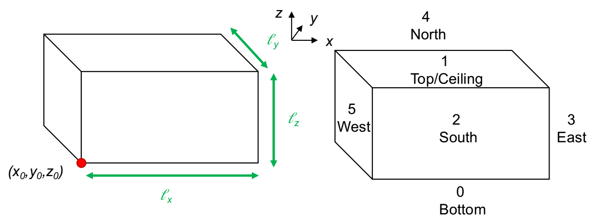
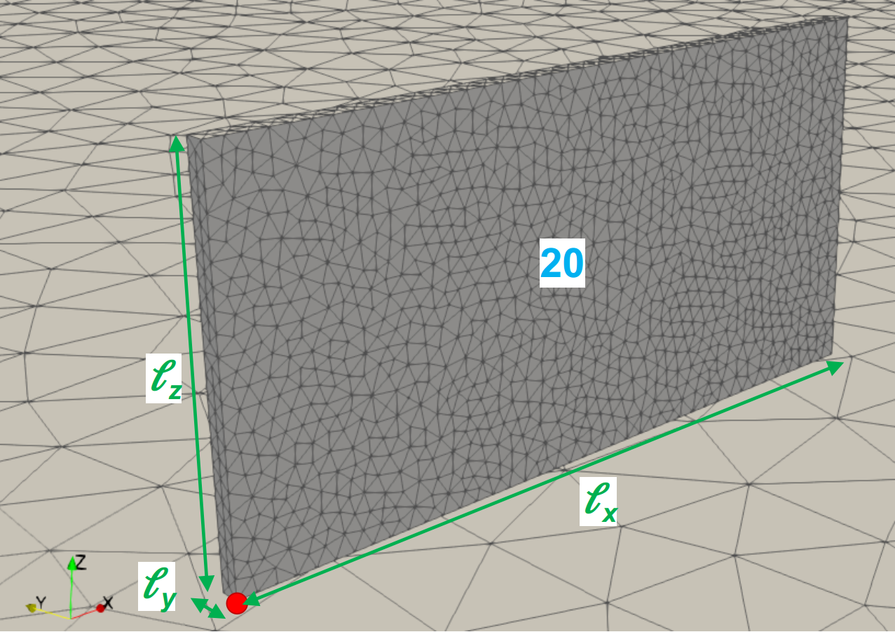
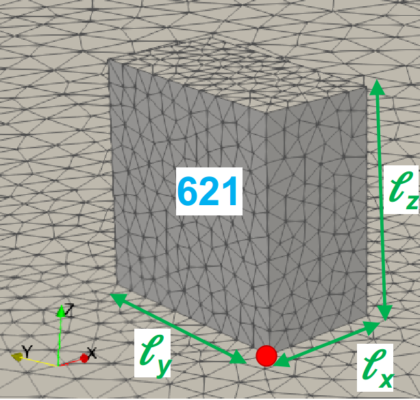
The 3D feature surfaces are named Bottom (id 0), Top/Ceiling (id 1), South (id 2), East (id 3), North (id 4) and West (id 5) as shown in Figure 1.1. Each rectangular box is defined by its size and its reference point as shown in Figure 1.1. By convention, the reference point is chosen to be always the minimum , and of the feature.
Remark: The reference point of the domain itself is . This implies that all the reference points of features are 3-tuples of positive values.
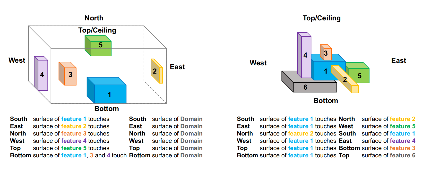
All these conventions imply that features will always touch each others following the same rules as summarised in Figure 1.2
1.4 Capabilities of IGG
1.4.1 What IGG can do…
By combining 2D features, generic rectangular boxes and bevels, furniture, accessories and humans, it is possible to generate very complex and realistic indoor environments: just be imaginative!
The 2D features supported by IGG are (Section 4.1):
-
•
Inlet of ventilation/heating
-
•
Outlet of ventilation/heating
-
•
Doors
-
•
Windows
The furniture (3D features) supported by IGG are (Section 4.2):
-
•
Box: rectangular box shape
-
•
Normal Shelf: rectangular box shape
-
•
Refrigerated Shelf: L-shape
-
•
Manual Till: rectangular box shape
-
•
Automatic Till: L-shape
-
•
Chair: complex shape
-
•
Seat: L-shape
-
•
Stool: complex shape
-
•
Table: complex shape
-
•
Bed: complex shape
-
•
Bevel: rectangular box shape with one inclined surface
The accessories (3D features) supported by IGG are (Section 4.3):
-
•
Screen separator: rectangular shape
-
•
Laptop: L-shape
-
•
Computer screen: complex shape
-
•
Computer tower: rectangular shape
-
•
Ceiling diffuser (exception: 2D feature)
-
•
Ceiling extractor (exception: 2D feature)
In addition, humans can be added into the geometry - see Section 5 for more details.
Finally, the mesh generated can be refined or coarsen in specific area if required (Section 6).
1.4.2 … and cannot do (limitations)
The limitations and known issues of IGG are the followings:
-
•
The geometry can only be based on rectangular or bevel shapes. Curved surfaces are not supported.
-
•
Features need to be aligned with cartesian coordinates: they cannot be rotated, i.e. rotated by an angle .
-
•
The output of IGG is the geometry and the mesh in GMSH format (*.geo and *.msh) suitable to run the CFD software Fluidity. *.stl format can be also generated if wanted by running gmsh -2 MyGeom.geo -o MyGeom.stl where MyGeom.geo is the output of IGG. Indeed, most of the commercial CFD software support *.stl format as mesh input.
-
•
If two features have only one edge in common (one single line - features attached by a corner): Fluidity mesh adaptivity capabilities will complain and most of the time crash. Even though this situation is supported and can be generated by IGG, it is recommended to avoid it to avoid future issues with Fluidity.
Chapter 2 Input files
The user needs to define the following 6 input files:
2.1 IGG_Numerics.dat: general options
The input file IGG_Numerics.dat (see Code 1) allows the user to specify:
-
•
Numerical variables To avoid rounded errors Round and Epsilon are used into IGG. Round is the number of digits kept after rounded a number and Epsilon is the tolerance used when comparing numbers (equality). It is recommended to keep them equal to 7 and , respectively as shown in Code 1.
-
•
File name is the root name the output files (geometry, mesh…) will have. In the example shown in Code 1, the root filename will be MyGeom.
-
•
GMSH path The user can specify where GMSH is located on the machine. gmsh will call the version installed by default. In case of several GMSH versions, the absolute path can be specified. It is re-called that GMSH v3.x is recommended.
-
•
Checkmesh path The user can specify where the checkmesh tool is located on the machine. checkmesh will use the checkmesh version installed by default on your machine (this should have been installed alongside Fluidity), otherwise its absolute path can be specified.
-
•
Outputs The user can choose to output or not the Mesh in GMSH format (*.msh) and/or the geometry/mesh in ParaView vtk format (*.vtk). T stands for True (they are outputted) and F for False (they are not). IGG always outputs the geometry in GMSH format (*.geo). If the mesh is outputted, the ParaView file *.vtk will show the 3D mesh, otherwise it will show the 2D mesh.
-
•
Check mesh consistency Once the mesh is created, the user can use two tools to check if the mesh is consistent to run CFD simulations. A tool coming alongside Fluidity ToolFluidity - checkmesh - and a tool coming alongside GMSH ToolGmsh. T stands for True (the mesh consistency is checked) and F for False (the mesh consistency is not checked).
-
•
Debug mode can be used if wanted - this can be useful for IGG developers only: if turned on, it is plotting each 2D surfaces of every feature. It is recommended to let it turned off.
2.2 IGG_Domain.dat: setup of the domain
The input file IGG_Domain.dat (see Code 1) allows the user to specify:
-
•
Domain size is specified by a 3-tuple . In the example Code 1, the domain is 20 m 20 m 3 m.
-
•
Periodicity can be used in (PerioX) and (PerioY) direction if wanted. T stands for True (periodicity) and F for False (no periodicity). If PerioX is T, the East and West surface of the domain are the “same”. If PerioY is T, the North and South surface of the domain are the “same”.
-
•
Inlets, outlets, doors and windows need to be specified in this order. For each feature type, the number of the feature should be given first: in the example in Code 1, there are 2 inlets, 1 outlet, 1 door and 2 windows. Then, the location and the size of each feature is given.
Remark: The inlets, outlets, doors and windows are 2D features: this implies that one of their three size is equal to . In Code 1 for example, the size of Inlet 1 is : its size along , i.e. , is equal to zero, i.e. Inlet 1 is on a -plane.
2.3 IGG_Furniture.dat: furniture into the domain
The input file IGG_Furniture.dat (see Code 1) allows the user to specify the number, the type, the location and the size of the furniture into the domain.
-
•
The total number of furniture into the domain is given at the first line. In Code 1 for example, there is 10 furniture.
-
•
Each Furniture is then defined: the first line specifies the furniture type, then following lines provide the position and the size of the furniture. The furniture type keywords list is: Box, NShelf, RShelf, MTill, ATill, Bed, Stool, Table, Seat, Chair, Bevel. See Section 4.2 for more details about how to define each furniture type.
2.4 IGG_Accessories.dat: accessories into the domain
The input file IGG_Accessories.dat (see Code 1) allows the user to specify the number, the type, the location and the size of the accessories into the domain.
-
•
The total number of accessories into the domain is given at the first line. In Code 1 for example, there is 4 accessories.
-
•
Each Accessories is then defined: the first line specifies the furniture type, then following lines provide the position and the size of the accessory. The accessory keywords list is: Tower, Screen, Laptop, Separator, Diffuser, Extractor. See Section 4.3 for more details about how to define each accessories type. NB: Note that Diffuser and Extractor are 2D features.
2.5 IGG_Humans.dat: people into the domain
The input file IGG_Humans.dat (see Code 1) allows the user to specify the number, the height, the weight profile, the activity, the location… of people into the domain.
-
•
The total number of humans is given at the first line. In Code 1 for example, there are 3 humans.
-
•
Human details allow the user to specify which part of the human is being represented into the geometry. Humans are divided into 10 parts: Head, Neck, Arms, Forearms, Hands, Trunk, Pelvis, Thighs, Legs and Feet. T stands for True and F for False.
-
•
Each Human is then defined. The keywords list defining a human is (no specific order required): Activity (mandatory), Height (optional), Weight (optional), Forearm (optional), FaceDirection (optional), Centre (mandatory if Activity is Standing, optional otherwise), Furniture (mandatory if Activity is Sitting or Lying), LyingPosition (mandatory if Activity is Lying), NoseModel (optional), MouthModel (optional), NoseArea (optional), MouthArea (optional), NoseAngle (optional), HeatingPart (optional). See Section 5 for more details about how to define humans.
2.6 IGG_Mesh.dat: mesh characteristics
The input file IGG_Mesh.dat (see Code 1) allows the user to specify the mesh characteristics.
-
•
General mesh sizes are firstly defined. NMinElement is the minimum number of elements on one surface. MinLength and MaxLength are the minimum and maximum edge length of the mesh, respectively.
-
•
Constraints can be added to the mesh. First, the number of constraints is defined, e.g. 7 constraints are specified in Code 1; then the constraints are specified. See Section 6 for more details.
-
–
Feature-specific constraint: the feature type to refine is specified, then the edge length wanted given.
-
–
Non-feature-specific constraint: the user can refined/coarsen the mesh in some areas if wanted. The area to be refined/coarsen can be defined by a box or a sphere.
-
–
Chapter 3 Output files
Assuming that the File Name defined in IGG_Numerics.dat is MyGeom, the output files generated are:
3.1 *.geo file: GMSH geometry
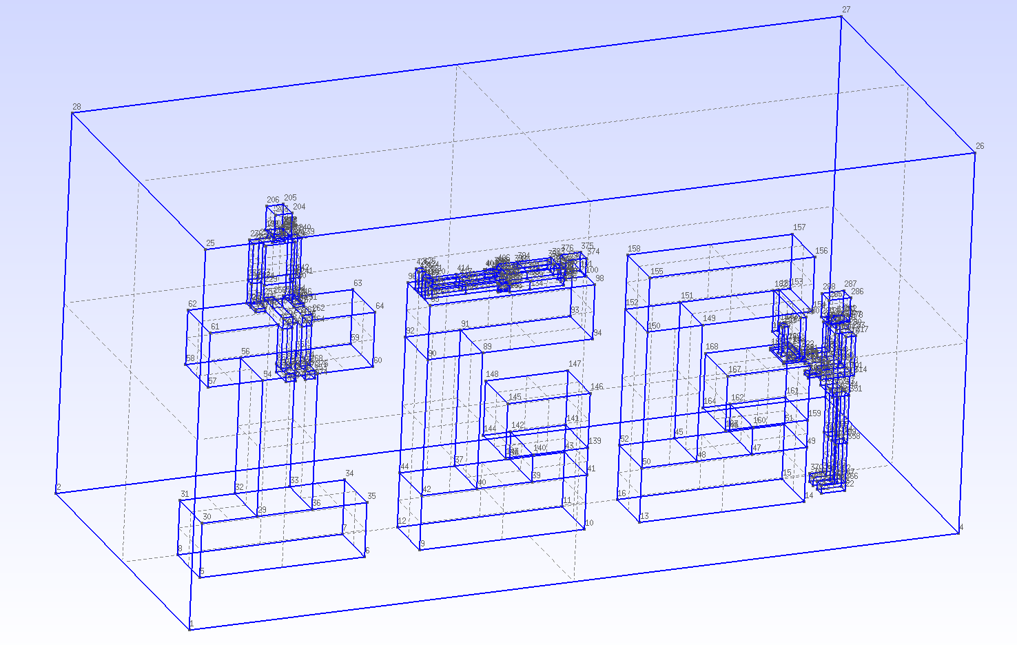
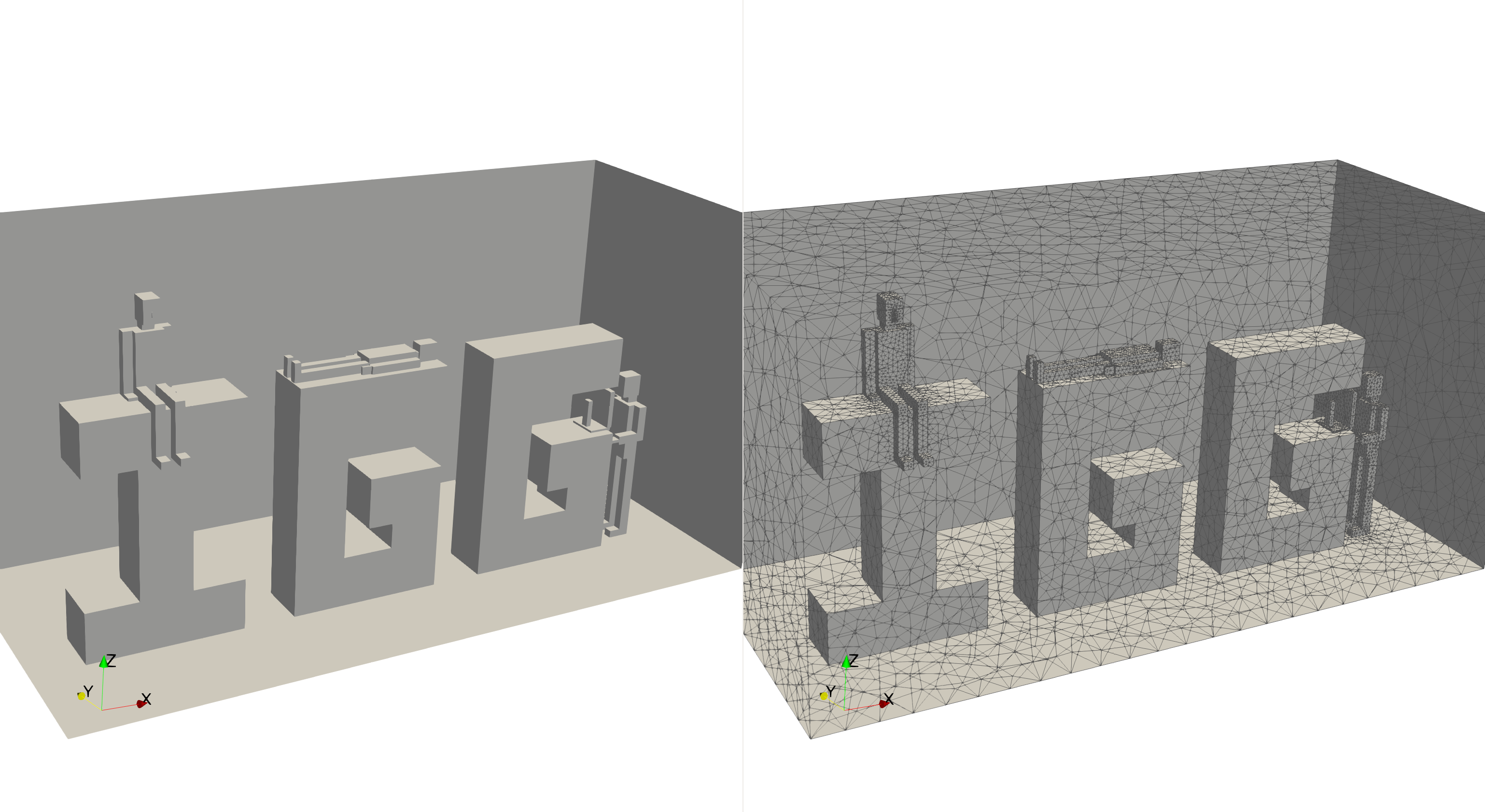
Assuming that the File Name defined in IGG_Numerics.dat is MyGeom, the geometry in GMSH format outputted is MyGeom.geo and can be visualised using the graphical interface of GMSH by running Command 1 in a terminal. The IDs of points, lines, surfaces… can be seen on the graphical interface of GMSH for convenience. In GMSH, under Tools/Options/Geometry/Visibility/, the Point labels, Line labels and Surface labels can be easily displayed. An example of *.geo file visualisation in GMSH is shown in Figure 3.1.
3.2 *.msh file: GMSH mesh
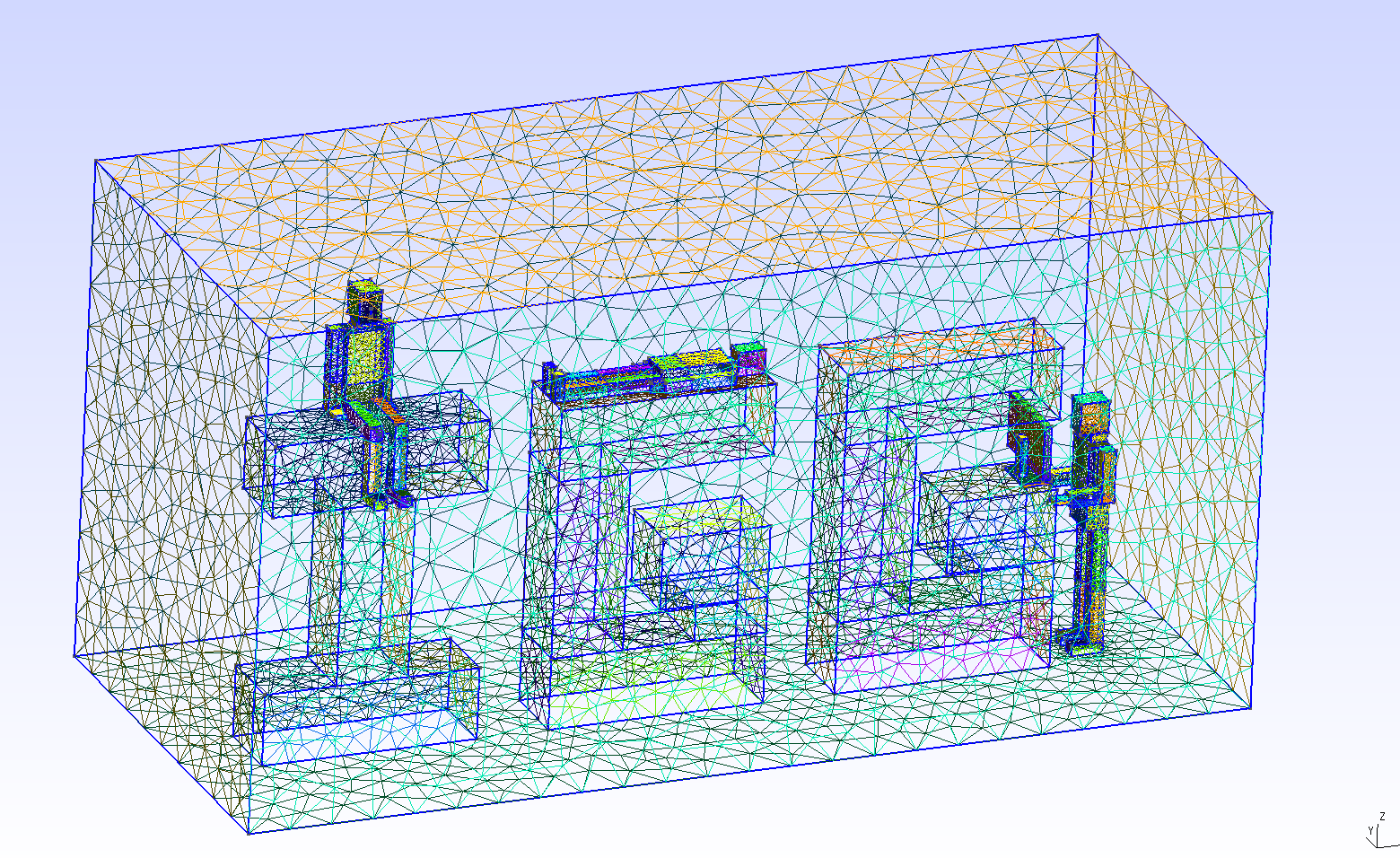
The mesh is outputted if the option Mesh in IGG_Numerics.dat is True T. Assuming that the File Name defined in IGG_Numerics.dat is MyGeom, the mesh in GMSH format outputted is MyGeom.msh and can be visualised using the graphical interface of GMSH by running Command 2 in a terminal. An example of *.msh file visualisation in GMSH is shown in Figure 3.2.
3.3 *vtk: ParaView file
The ParaView file is outputted if the option vtk in IGG_Numerics.dat is True T. If Mesh is True T, the user will be able to see the 3D mesh into the ParaView file, if Mesh is False F, the user will be able to see the 2D mesh only into the vtk file.
Assuming that the File Name defined in IGG_Numerics.dat is MyGeom, the geometry/mesh in ParaView format outputted is MyGeom.vtk and can be visualised using the graphical interface of ParaView by running Command 3 in a terminal. An example of *.vtk file visualisation in ParaView is shown in Figure 3.3
3.4 *_HumansStates.dat: summary of humans state
Assuming that the File Name defined in IGG_Numerics.dat is MyGeom, a summary of the human state is given in MyGeom_HumansStates.dat and can be open with a text editor. It consists in 3 part:
-
•
At the beginning of the file, it is re-called how the physical IDs of humans are defined. This is also explained in this manual in Section 7.1.2.
-
•
As the user can let IGG uses the default values for, amongst other, the Height, the Weight…, MyGeom_HumansStates.dat summarises the values and characteristics used for each human.
-
•
The area of each body part are summarised at the end of MyGeom_HumansStates.dat.
3.5 *_PhysicalIDs.dat: summary of the physical IDs
Assuming that File Name defined in IGG_Numerics.dat is MyGeom, MyGeom_PhysicalIDs.dat summarises the Physical IDs assigned to surfaces. These Physical IDs are needed by Fluidity to apply boundary conditions. In the first part of the file, the Physical IDs by feature types (furniture, accessories, humans…) are summarised. In a second part, an attempt is done to group the Physical IDs by boundary conditions types, i.e. walls, heating, inlet, outlet, heat generation… The Physical IDs are grouped by common boundary conditions used in CFD - but the user can decide to use different boundary conditions than the ones suggested. More details about the Physical IDs are given in Section 7.
Chapter 4 Features supported by IGG
Features are divided into 2D features defined in IGG_Domain.dat, furniture defined in IGG_Furniture.dat and accessories defined in IGG_Accessories.dat. Each feature types and how to define them in their respective input files are described in this chapter.
4.1 2D features: inlets, outlets, doors and windows
In IGG_Domain.dat, the inlets, outlets, doors and windows can be added, and need to be defined in this specific order: inlets, outlets, doors then windows. These 4 features are 2D and are defined by their location and then their size . Code 1 shows how to define these features. For each feature type, the following need to be defined:
-
•
First the number of feature is given;
-
•
Then each feature of this type is defined by giving in this order:
-
–
its location and
-
–
its size .
-
–
Remark 1: By convention, the location, i.e. the reference point, is chosen to be always the minimum , and of the feature.
Remark 2: The inlets, outlets, doors and windows are 2D features: this implies that one of their three sizes is null:
-
•
If is equal to zero, the 2D feature is defined on a -plane;
-
•
if is equal to zero, the 2D feature is defined on a -plane;
-
•
if is equal to zero, the 2D feature is defined on a -plane.
Remark 3: If one or several of these 2D features are not intended to be in the geometry, set the number of the feature type equal to 0 as shown in Code 2.
Remark 4: These 2D features can be located on any surfaces of the domain, furniture or accessories; even humans (!) if wanted.
The physical IDs of these 2D features have the form xyy, where:
-
•
x is the integer:
-
–
1 for an inlet
-
–
2 for an outlet
-
–
3 for a door
-
–
4 for a window
-
–
-
•
yy is an integer referring to the feature number from 01 to 99 as defined in IGG_Domain.dat.
Example: the physical ID 102 refers to the inlet number 2 defined in IGG_Domain.dat; the physical ID 410 refers to the window number 10 defined in IGG_Domain.dat.
Ceiling diffuser or extractor
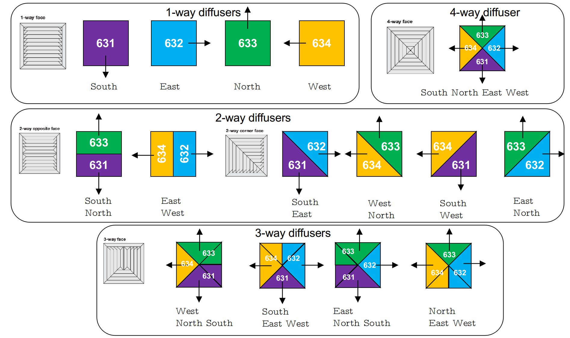
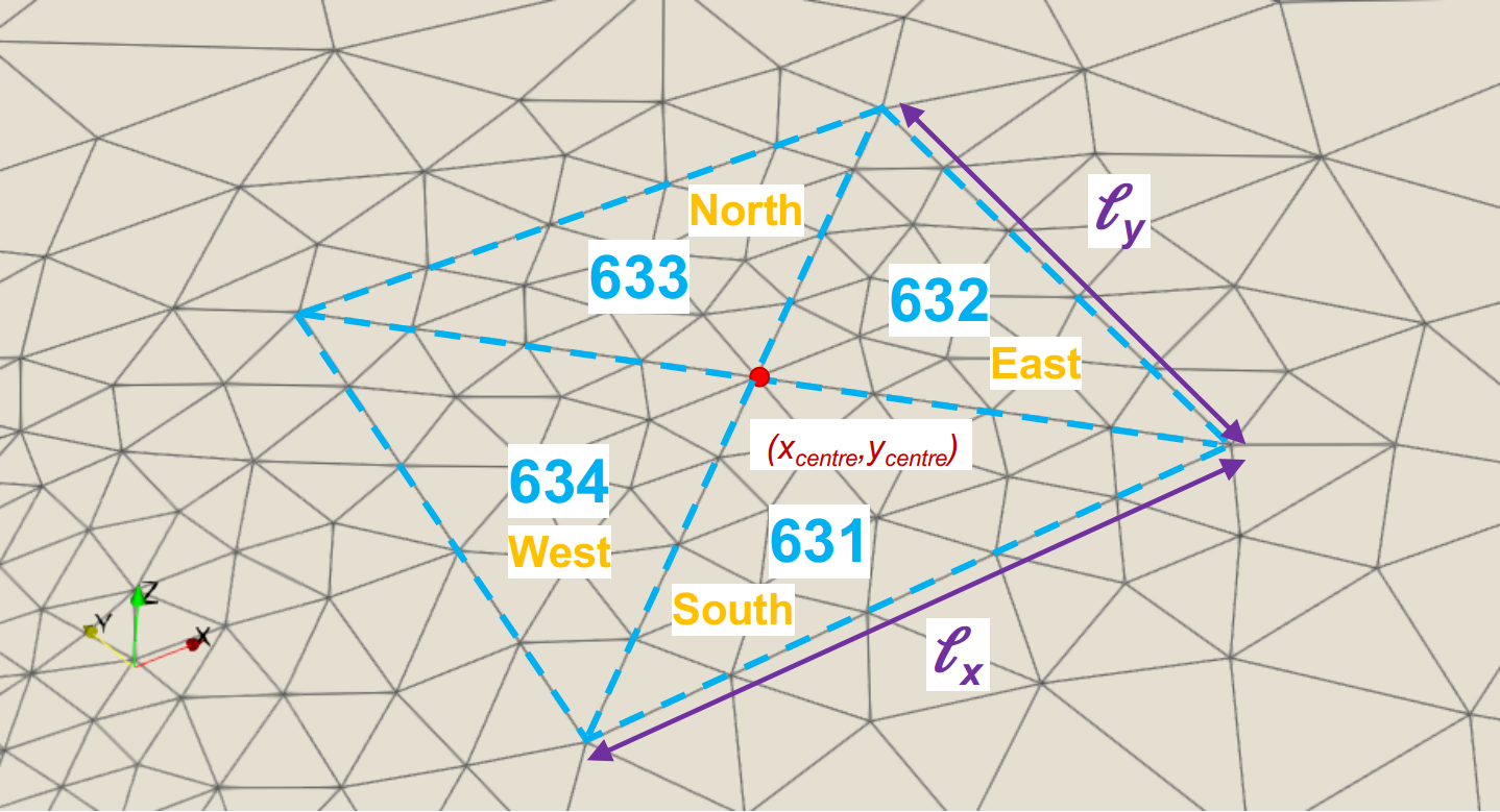
Note that it exists two other 2D feature defined under IGG_Accessories.dat: Diffuser and Extractor. A diffuser/extractor is a 2D feature located at ceiling height (only for now!). The user needs to defined its centre as well as its size as shown in Code 3. The diffuser/extractor is divided into sub-shaped depending the in/out air direction desired, i.e. inlet/outlet of the flow towards North, South, East and/or West. This allows the user to generate 1-way, 2-way, 3-way or 4-way diffusers/extractors.
The physical IDs defining the diffuser are:
-
•
631 for the surface where the air is released towards the South
-
•
632 for the surface where the air is released towards the East
-
•
633 for the surface where the air is released towards the North
-
•
634 for the surface where the air is released towards the West
The physical IDs defining the extractor are:
-
•
641 for the surface where the air is extracted towards the South
-
•
642 for the surface where the air is extracted towards the East
-
•
643 for the surface where the air is extracted towards the North
-
•
644 for the surface where the air is extracted towards the West
Schematic of the diffusers as represented in IGG are shown in Figure 4.1. Extractor are represented as the same, excepted the air is extracted, i.e. going out of the domain.
4.2 Furniture
The furniture, which are defined by the user in IGG_Furniture.dat, supported by IGG are summarised in Table 4.1.
| Furniture type | Shape | Keyword | Physical ID | Section |
|---|---|---|---|---|
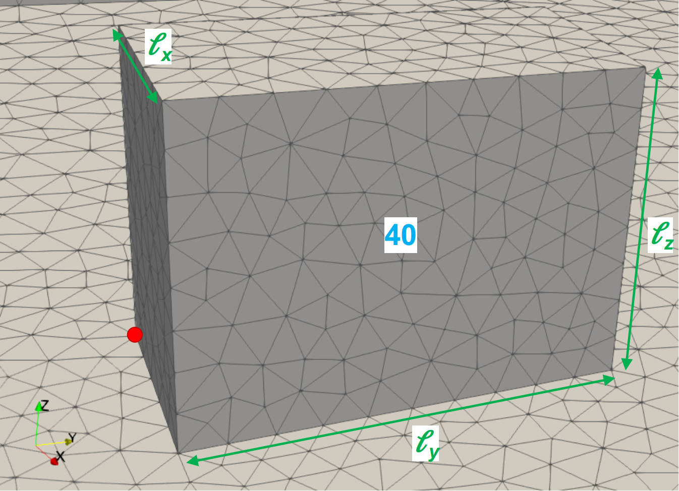
| Box | Rectangular Box | Box | 40 | 4.2.1 |
| Normal Shelf | Rectangular box | NShelf | 30 | 4.2.2 |
| Refrigerated Shelf | L-shape | RShelf |
311 cold surfaces
312 otherwise |
4.2.3 |
| Manual Till | Rectangular box | MTill | 32 | 4.2.4 |
| Automatic Till | L-shape | ATill | 33 | 4.2.5 |
| Table | 5 rectangular boxes | Table |
341 top surface
342 otherwise |
4.2.6 |
| Chair | 8 rectangular boxes | Chair |
351 in-contact w/ people surfaces
352 otherwise |
4.2.7 |
| Seat | L-shape | Seat |
361 in-contact w/ people surfaces
362 otherwise |
4.2.8 |
| Stool | 5 rectangular boxes | Stool |
371 top surface
372 otherwise |
4.2.9 |
| Bed | 11 rectangular boxes | Bed |
381 mattress top surface
382 otherwise |
4.2.10 |
| Bevel | Bevel | Bevel | 39x: x=bevel ID | 4.2.11 |
4.2.1 Box
A generic box (keyword: Box) is a rectangular box object. A box is defined, in this order, by:
-
•
its keyword Box;
-
•
its location and
-
•
its size ,
4.2.2 Normal Shelf
A normal shelf (keyword: NShelf) is a rectangular box object. A normal shelf is defined, in this order, by:
-
•
its keyword NShelf;
-
•
its location and
-
•
its size ,

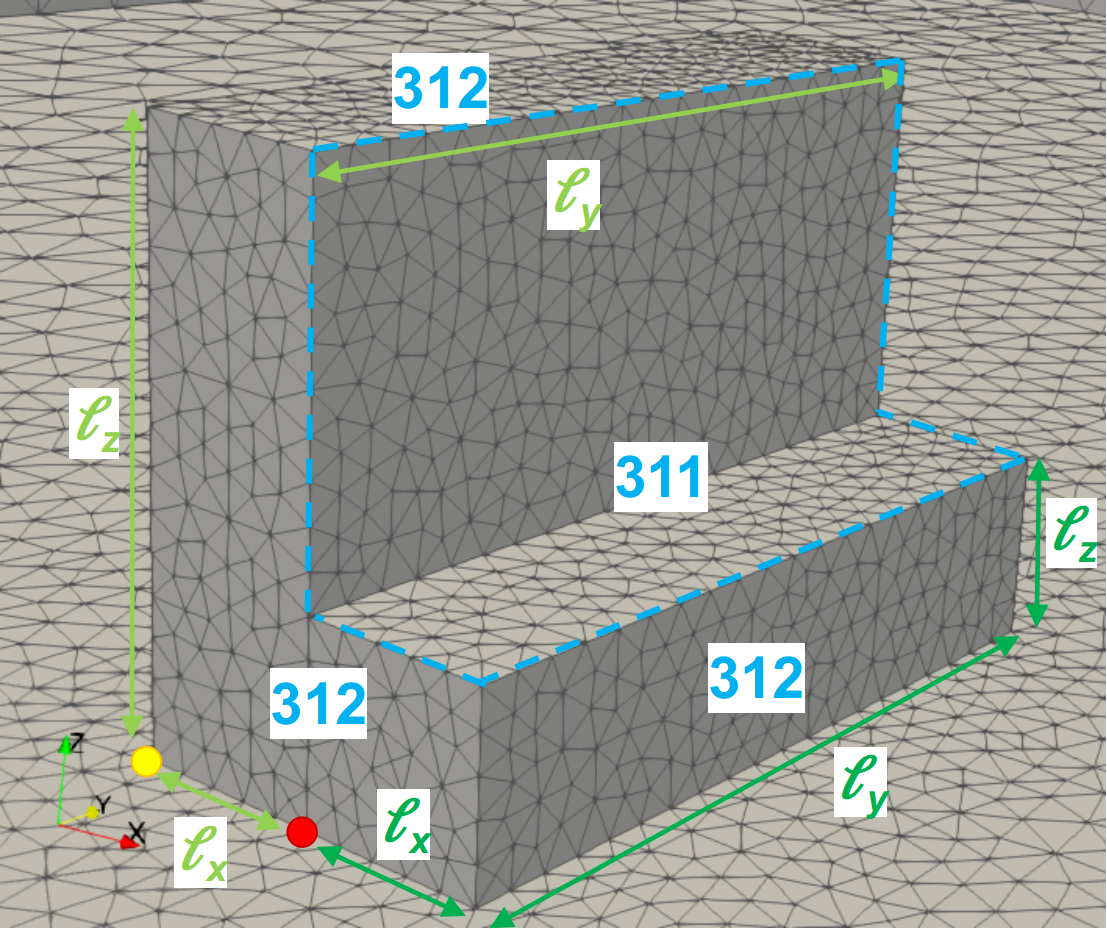
4.2.3 Refrigerated shelf
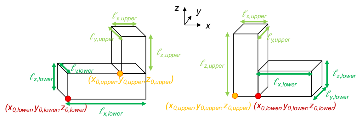
A refrigerated shelf (keyword: RShelf) is a L-shape object: in other words, refrigerated shelf is a compound of 2 rectangular boxes. A refrigerated shelf is defined, in this order, by:
-
•
its keyword RShelf;
-
•
its lower part location ,
-
•
its lower part size ,
-
•
its upper part location and
-
•
its upper part size ,
as shown in Code 3 and in Figure 4.4. It exists two ways to represent refrigerated shelf, and more generally L-shape object, as shown in Figure 4.4(a): both are supported by IGG, and the user can use one or the other. The physical surface IDs of every refrigerated shelf is 31x, where x is equal to 1 for the “cold” surfaces or 2 otherwise. A refrigerated shelf has 2 “cold” surfaces being the top surface of the lower part and the adjacent lateral surface of the upper part as shown in Figure 4.4(b).
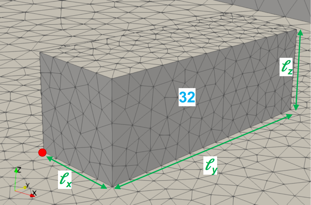
4.2.4 Manual Till
A manual till (keyword: MTill) is a rectangular box object. A manual till is defined, in this order, by:
-
•
its keyword MTill;
-
•
its location and
-
•
its size ,
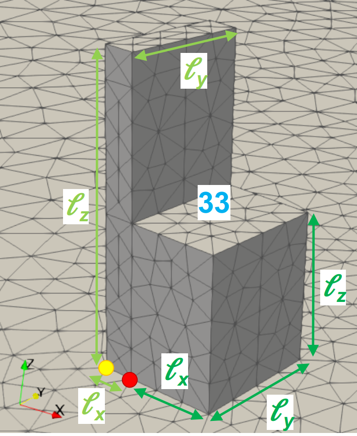
4.2.5 Automatic Till
An automatic till (keyword: ATill) is a L-shape object: in other words, automatic till is a compound of 2 rectangular boxes. A automatic till is defined, in this order, by:
-
•
its keyword MTill;
-
•
its lower part location ,
-
•
its lower part size ,
-
•
its upper part location and
-
•
its upper part size ,
as shown in Code 5 and in Figure 4.6. It exists two ways to represent automatic till, and more generally L-shape object, as shown in Figure 4.4(a): both are supported by IGG, and the user can use one or the other. The physical surface ID of every automatic till is 33.
Remark: It is intended to implement a generic L-shape object in future version of IGG. For the time being, automatic till can be used as a generic L-shape object.
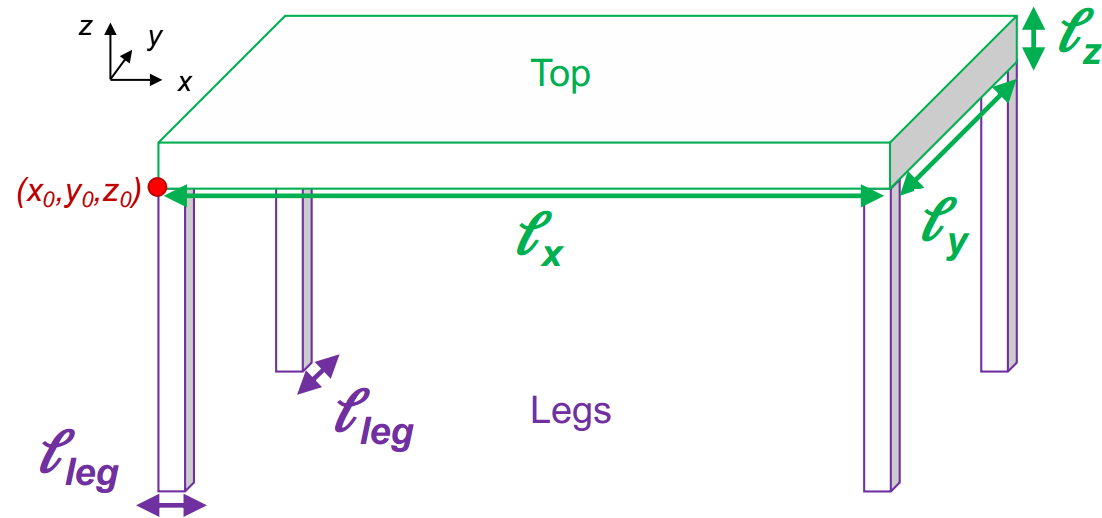
4.2.6 Table
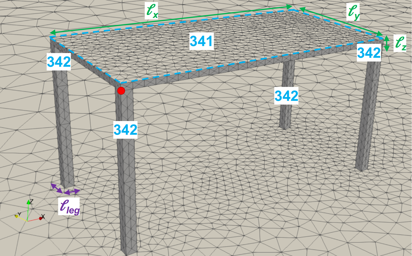
A table (keyword: Table) is a compound of 5 rectangular boxes: 4 legs and 1 top as shown in Figure 4.7(a).
Remarks about the table geometry: The 4 legs are assumed to have a square section having the same size as shown in Figure 4.7(a). The legs are set at the four corner of the top part.
A table is defined, in this order, by:
-
•
its keyword Table;
-
•
its top location ,
-
•
its top size and
-
•
its legs size ,
as shown in Code 6 and in Figure 4.7. The physical surface IDs of every table is 34x, where x is equal to 1 for the top surface of the top part or 2 otherwise as shown in Figure 4.7(b).
4.2.7 Chair
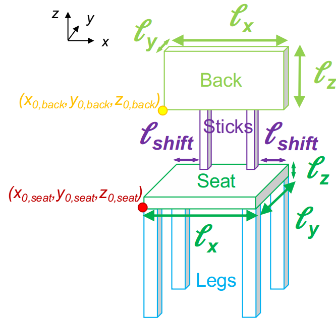
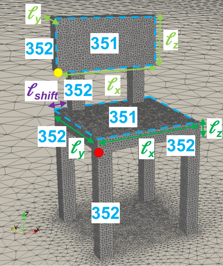
A chair (keyword: Chair) is a compound of 8 rectangular boxes: 4 legs, 1 seat, 2 back sticks and 1 back as shown in Figure 4.8(a).
Remarks about the chair geometry: The 4 legs and the 2 back sticks are assumed to have a square section having the same size than the thickness of the seat and the back, respectively. The user does not have the control of the legs and stick dimensions and shape - they are determined automatically in IGG. The legs are set at the four corner of the seat part. The back size can be smaller or bigger than the seat size. In addition, the user has the possibility to have a shift in the location of the back sticks relative to the seat (see in Figure 4.8(a)). It is believed that, for now, all these assumptions are fine as we are not intended to model Ikea catalogue!
A chair is defined, in this order, by:
-
•
its keyword Chair;
-
•
its seat location ,
-
•
its seat size ,
-
•
its back location ,
-
•
its back size and
-
•
its length by which the back sticks are shifted compared to the seat ,
as shown in Code 7 and in Figure 4.8. The physical surface IDs of every chair is 35x, where x is equal to 1 for the surfaces in contact with potential people sitting on it or 2 otherwise. A chair has 2 “in-contact with people” surfaces being the top surface of the seat and the adjacent lateral surface of the back as shown in Figure 4.8(b).
4.2.8 Seat
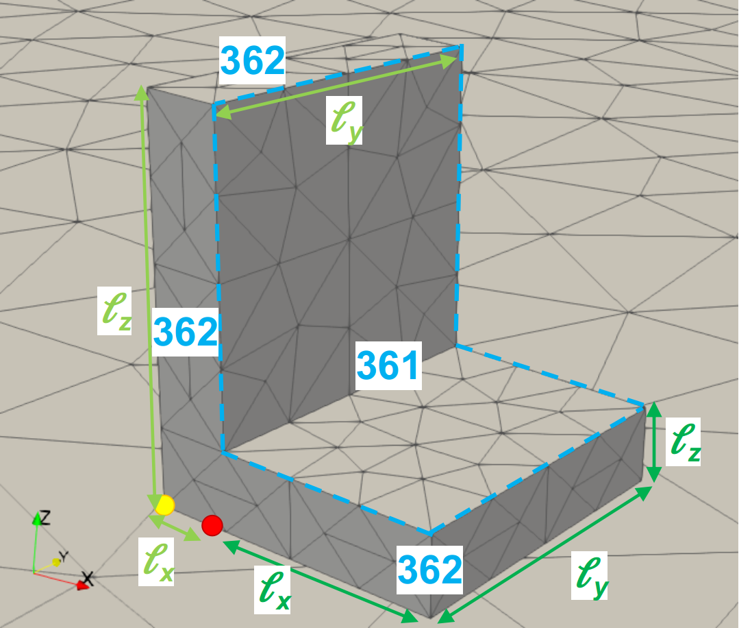
A seat (keyword: Seat) is a L-shape object: in other words, a seat is a compound of 2 rectangular boxes. A seat is defined, in this order, by:
-
•
its keyword Seat;
-
•
its lower part location ,
-
•
its lower part size ,
-
•
its upper part location and
-
•
its upper part size ,
as shown in Code 8 and in Figure 4.9. It exists two ways to represent seats, and more generally L-shape object, as shown in Figure 4.4(a): both are supported by IGG, and the user can use one or the other. The physical surface IDs of every seat is 36x, where x is equal to 1 for the surfaces in contact with potential people sitting on it or 2 otherwise. A seat has 2 “in-contact with people” surfaces being the top surface of the lower part and the adjacent lateral surface of the upper part as shown in Figure 4.9.
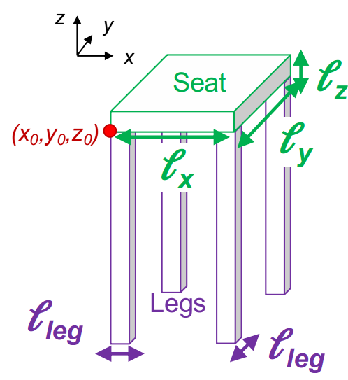
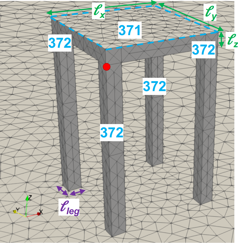
4.2.9 Stool
A stool (keyword: Stool) is a compound of 5 rectangular boxes: 4 legs and 1 seat as shown in Figure 4.10(a).
Remarks about the stool geometry: The 4 legs are assumed to have a square section having the same size as shown in Figure 4.10(a). The legs are set at the four corner of the seat.
A stool is defined, in this order, by:
-
•
its keyword Stool;
-
•
its seat location ,
-
•
its seat size and
-
•
its legs size ,
as shown in Code 9 and in Figure 4.10. The physical surface IDs of every stool is 37x, where x is equal to 1 for the top surface of the seat or 2 otherwise as shown in Figure 4.10(b).
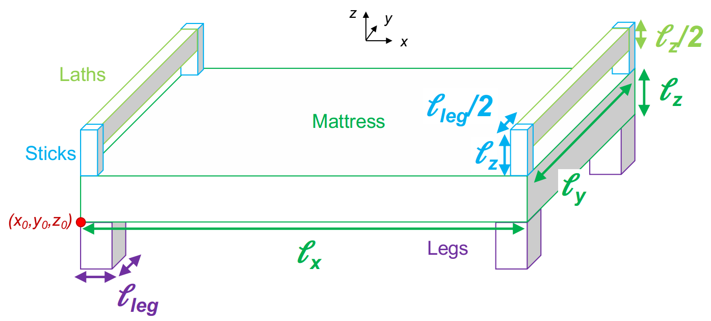
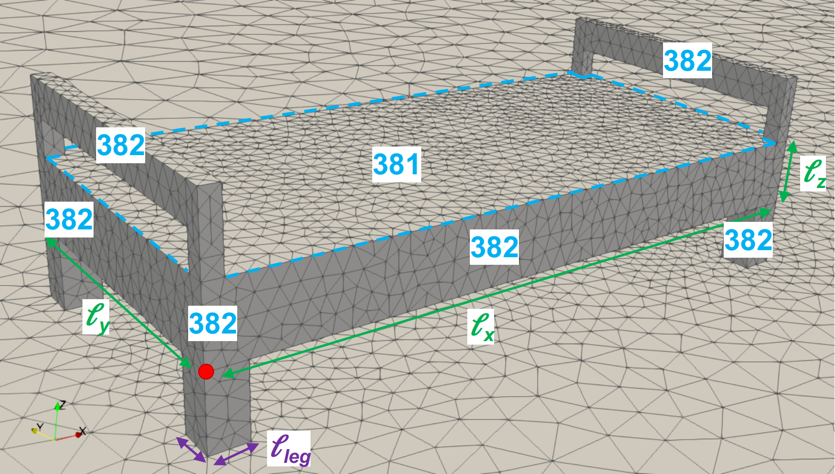
4.2.10 Bed
A bed (keyword: Bed) is a compound of 11 rectangular boxes: 4 legs, 1 mattress, 4 sticks and 2 laths as shown in Figure 4.11(a).
Remarks about the bed geometry: The 4 legs are assumed to have a square section having the same size as shown in Figure 4.11(a). The legs are set at the four corner of the mattress. It is assumed that the 4 sticks, linking the laths, have square section twice smaller than the legs, i.e. and have the same height than the mattress, i.e., . Finally, the laths height is assumed to be twice smaller than the mattress height, i.e. . The remaining dimensions are deduced naturally from the mattress and sticks sizes.
A bed is defined, in this order, by:
-
•
its keyword Bed;
-
•
its mattress location ,
-
•
its mattress size and
-
•
its legs size ,
as shown in Code 10 and in Figure 4.11. The physical surface IDs of every bed is 38x, where x is equal to 1 for the top surface of the mattress or 2 otherwise as shown in Figure 4.11(b).
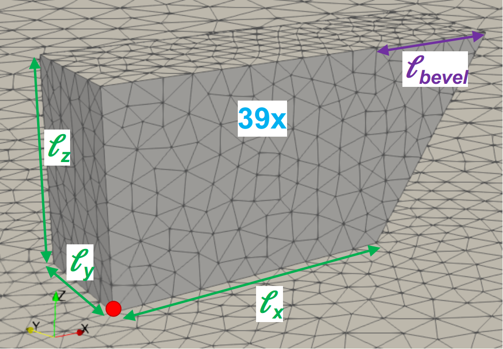
4.2.11 Bevel
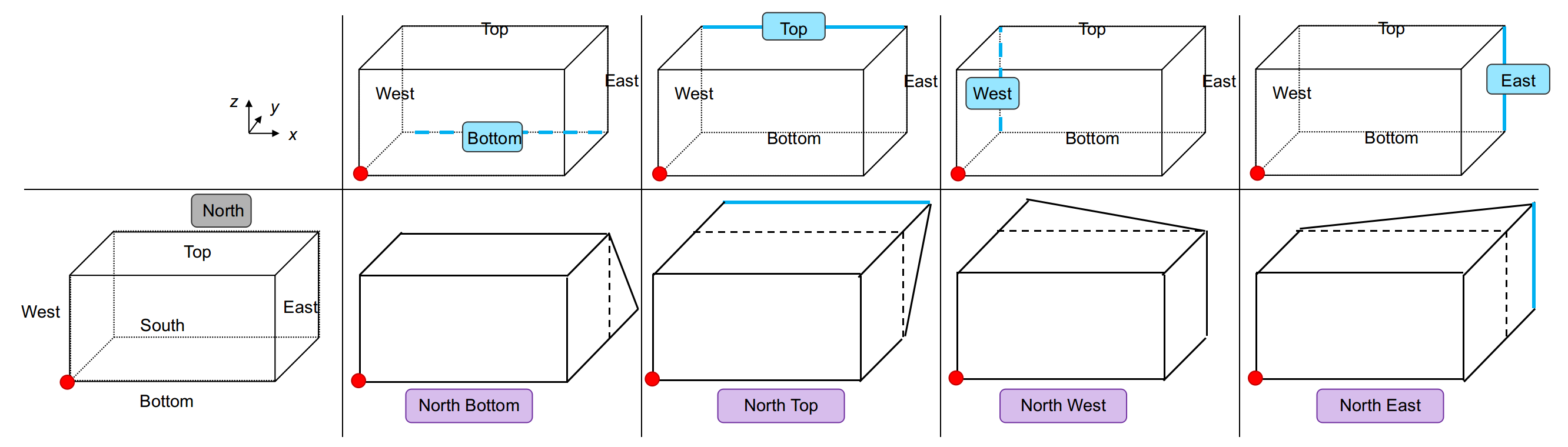
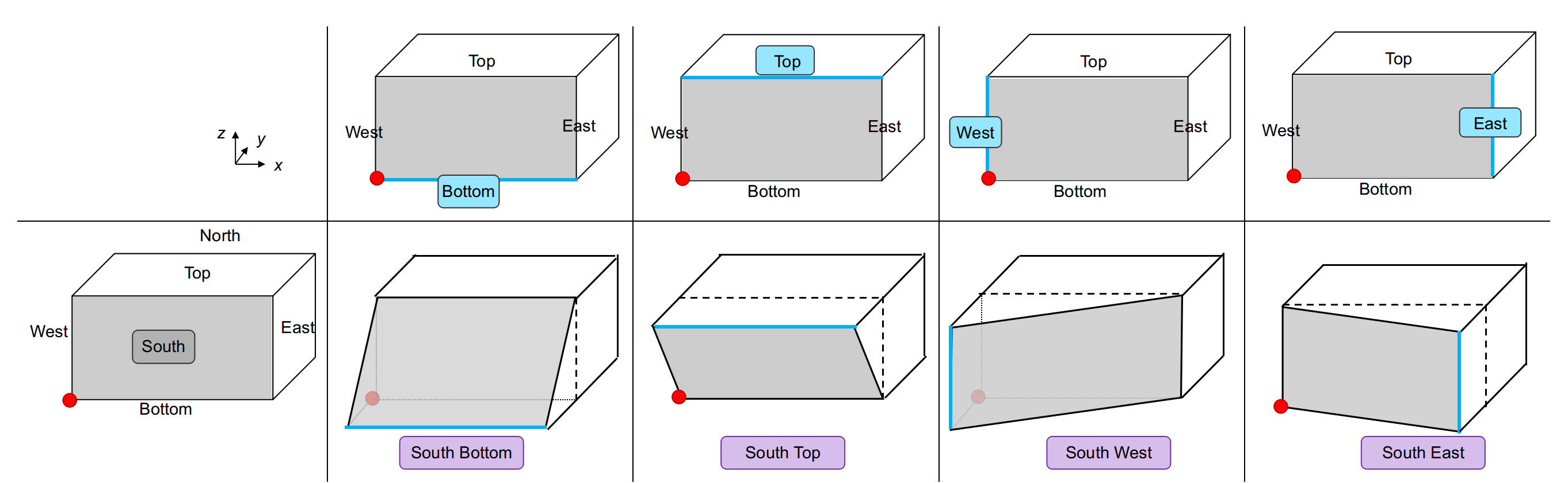
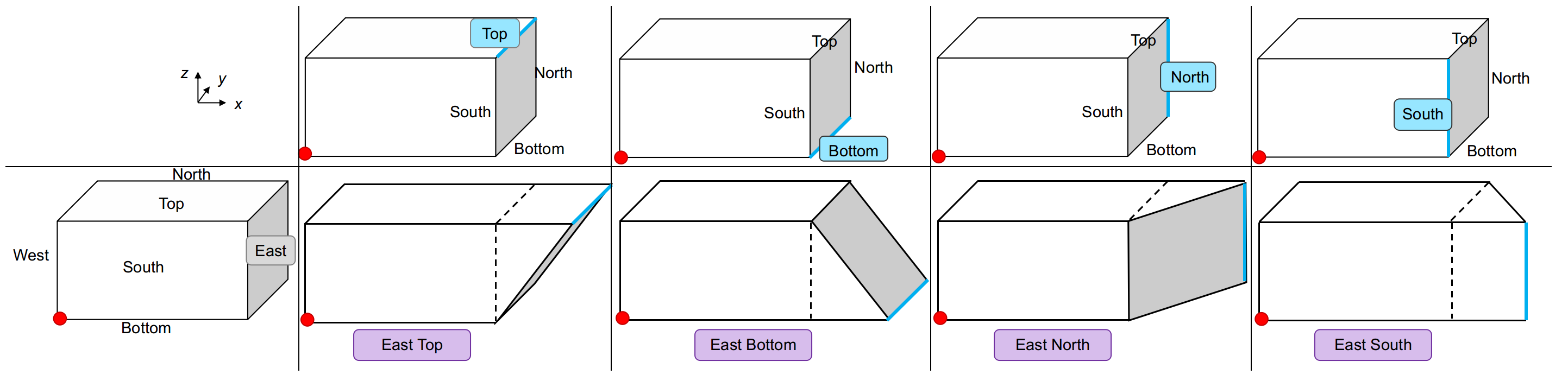
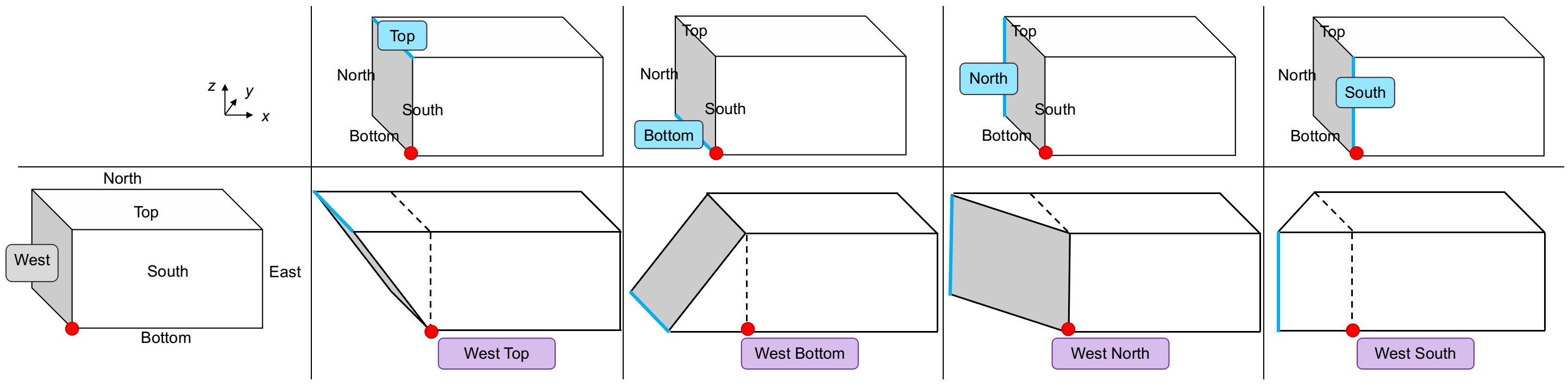
A bevel (keyword: Bevel) is a rectangular box with one of its surface having an inclination that meets the other surfaces at any angle but 90°, i.e. a rectangular box with one inclined surface, as shown in Figure 4.12(a).
A bevel is defined, in this order, by:
-
•
its keyword Bevel;
-
•
its bevel orientation and direction Surface1 Surface2;
-
•
its location ,
-
•
its size and
-
•
its bevel size ,
as shown in Code 11 and in Figure 4.12. The physical surface IDs of every bevel is 39x, where x is the ID of the bevel. For example, if there are 2 bevels into the domain, they will have the physical IDs 391 and 392. In future version of IGG, bevels will be encapsulated under one unique physical ID.
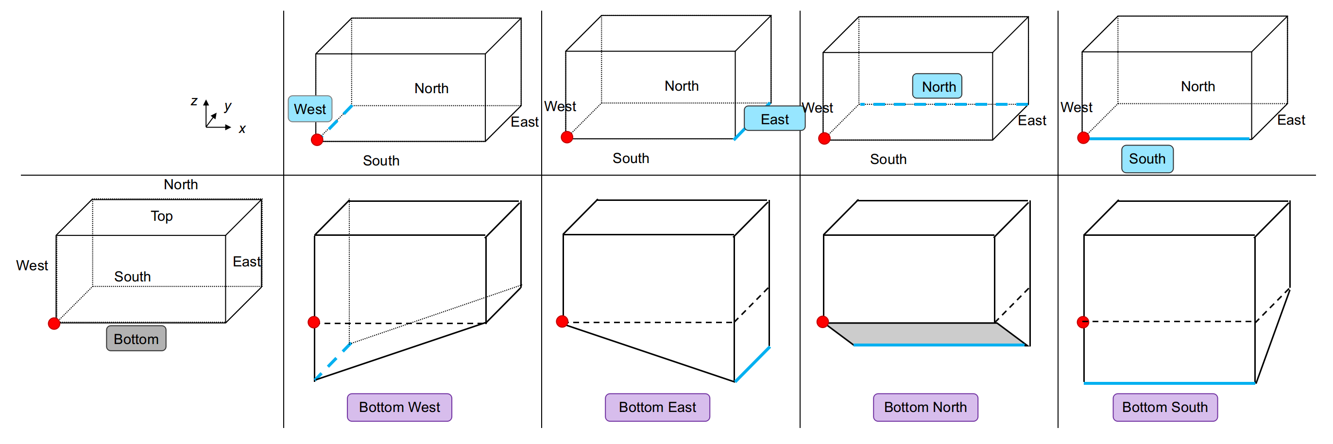
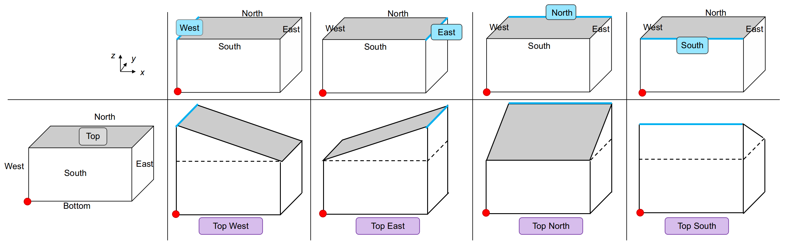
When defining a bevel, the location and direction of the bevel need to be specified. Surface1 designates the surface of the rectangular box where the inclined surface is located, while Surface2 designates which edge needs to be “moved” to create the bevel. The user can refer to Figure 4.14 which summarises all the different bevel possibilities and the Surface1 Surface2 (in purple) that need to be used.
4.3 Accessories
The accessories, which are defined by the user in IGG_Accessories.dat, supported by IGG are summarised in Table 4.2.
| Accessories type | Shape | Keyword | Physical ID | Section |
|---|---|---|---|---|
| Separator | Rectangular box | Separator | 20 | 4.3.1 |
| Laptop | L-shape | Laptop |
601 hot surfaces
602 otherwise |
4.3.2 |
| Screen | 3 rectangular boxes | Screen |
611 hot screen surface
612 otherwise |
4.3.3 |
| Computer tower | Rectangular box | Tower | 621 | 4.3.4 |
| Diffuser |
Rectangular boxes
Triangles |
Diffuser |
631 South
632 East 633 North 634 West |
4.3.5 |
| Extractor |
Rectangular boxes
Triangles |
Extractor |
641 South
642 East 643 North 644 West |
4.3.6 |
4.3.1 Separator
A plastic separator (keyword: Separator) is a rectangular box object. A plastic separator is defined, in this order, by:
-
•
its keyword Separator;
-
•
its location and
-
•
its size ,
4.3.2 Laptop
A laptop (keyword: Laptop) is a L-shape object: in other words, a laptop is a compound of 2 rectangular boxes. A laptop is defined, in this order, by:
-
•
its keyword Laptop;
-
•
its location in space ,
-
•
its screen size in inch ,
-
•
its furniture on which it stands FurnitureID and
-
•
its screen direction ScreenDirection, i.e. the direction/surface of the domain the laptop screen is facing: East, West, South or North;
as shown in Code 2 and in Figure 4.16. The physical surface IDs of every laptop is 60x, where x is equal to 1 for the “hot” surfaces or 2 otherwise. A laptop has 2 “hot” surfaces being the screen and the keyboard as shown in Figure 4.16.
Remark 1: Be careful, here the centre of the laptop is required.
Remark 2: The screen size need to be given in inches.
Remark 3: The furniture ID is an integer and is the ID of the furniture as it appears in IGG_Furniture.dat. If the laptop is on the ground, use the ID 0.
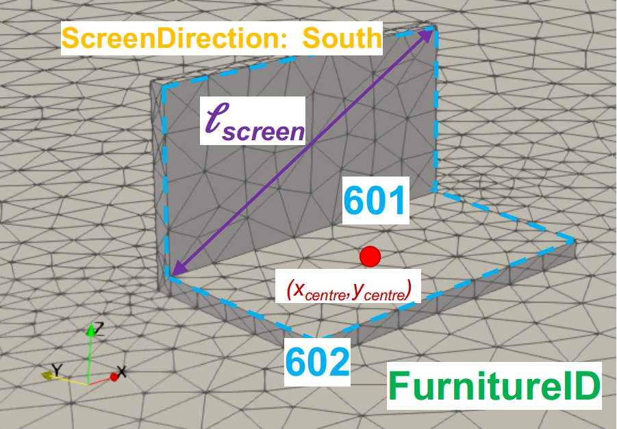
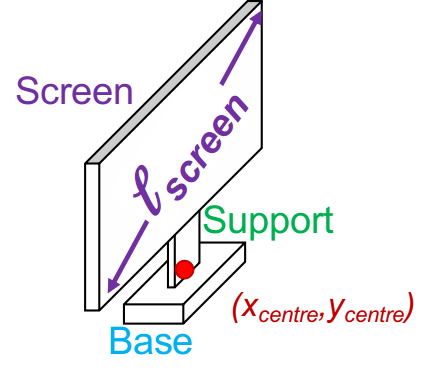
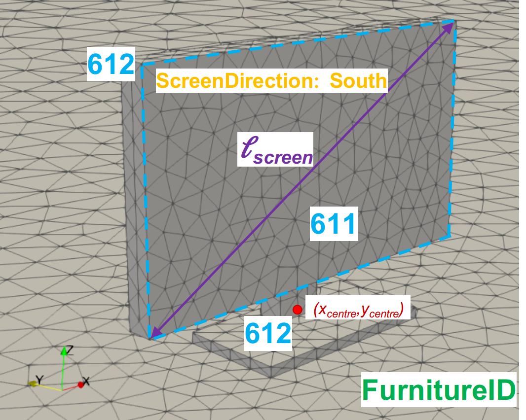
4.3.3 Screen
A screen (keyword: Screen) is is a compound of 3 rectangular boxes: 1 screen, 1 base and 1 support as shown in Figure 4.17(a).
A screen is defined, in this order, by:
-
•
its keyword Screen;
-
•
its location in space ,
-
•
its screen size in inch ,
-
•
its furniture on which it stands FurnitureID and
-
•
its screen direction ScreenDirection, i.e. the direction/surface of the domain the screen is facing: East, West, South or North;
as shown in Code 3 and in Figure 4.17. The physical surface IDs of every screen is 61x, where x is equal to 1 for the “hot” screen surface or 2 otherwise as shown in Figure 4.17(b).
Remark 1: Be careful, here the centre of the screen is required.
Remark 2: The screen size need to be given in inches.
Remark 3: The furniture ID is an integer and is the ID of the furniture as it appears in IGG_Furniture.dat. If the laptop is on the ground, use the ID 0.
4.3.4 Computer Tower
A computer tower (keyword: Tower) is a rectangular box object. A computer tower is defined, in this order, by:
-
•
its keyword Tower;
-
•
its location and
-
•
its size ,
4.3.5 Ceiling Diffuser
A diffuser (keyword: Diffuser) is a 2D rectangular box object divided into smaller rectangles or triangles depending the diffuser type (see Section 4.1). A diffuser is defined, in this order, by:
-
•
its keyword Diffuser;
-
•
its ventilation direction North, South, East and/or West;
-
•
its location and
-
•
its size .
as shown in Code 5 and in Figure 4.19. The physical IDs defining the diffuser are:
-
•
631 for the surface where the air is released towards the South
-
•
632 for the surface where the air is released towards the East
-
•
633 for the surface where the air is released towards the North
-
•
634 for the surface where the air is released towards the West
Remark 1: Be careful, here the centre of the diffuser is required.
Remark 2: Only diffusers at ceiling height are supported.
Remark 3: If 1 ventilation direction is provided, it is a 1-way diffuser; if 2 are provided, it is a 2-way diffuser… Refer to Figure 4.19 to look at all the possibilities supported.
Remark 4: A diffuser can only be an inlet. It cannot be both an inlet/outlet. For example, if the diffuser is a 2-way diffuser, the two surfaces defining it behave as inlets.
4.3.6 Ceiling Extractor
An extractor (keyword: Extractor) is a 2D rectangular box object divided into smaller rectangles or triangles depending the diffuser type (see Section 4.1). An extractor is defined, in this order, by:
-
•
its keyword extractor;
-
•
its extract direction North, South, East and/or West;
-
•
its location and
-
•
its size .
as shown in Code 6 and in Figure 4.20. The physical IDs defining the extractor are:
-
•
641 for the surface where the air is extracted towards the South
-
•
642 for the surface where the air is extracted towards the East
-
•
643 for the surface where the air is extracted towards the North
-
•
644 for the surface where the air is extracted towards the West
Remark 1: Be careful, here the centre of the extractor is required.
Remark 2: Only extractors at ceiling height are supported.
Remark 3: If 1 extract direction is provided, it is a 1-way extractor; if 2 are provided, it is a 2-way extractor… Refer to Figure 4.1 to look at all the possibilities supported.
Remark 4: An extractor can only be an outlet. It cannot be both an inlet/outlet. For example, if the extractor is a 2-way extractor, the two surfaces defining it behave as outlets.

Chapter 5 Humans
Humans can be added into the geometry and parametrised into the input file IGG_Humans.dat. Assuming that the File Name defined in IGG_Numerics.dat is MyGeom, a summary of the human states is given in MyGeom_HumansStates.dat and can be open with a file editor. As the user can let IGG uses the default values for, amongst other, the Height, the Weight…, MyGeom_HumansStates.dat summarises the values and characteristics used for each human as well as the area of each body part.
5.1 Human geometry and body proportion
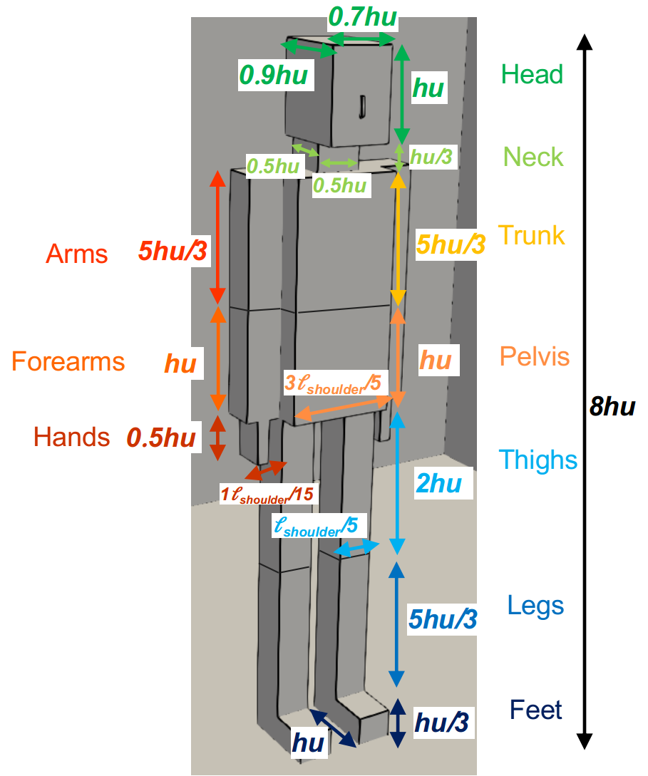
A human is a compound of 16 rectangular boxes for the body, 1 bevel for the nose and 1 2D feature for the mouth. The body parts are: 1 Head, 1 Neck, 1 Trunk, 2 Arms, 2 Forearms, 2 Hands, 1 Pelvis, 2 Thighs, 2 Legs and 2 Feet.
The body proportion of the human are following standards based on the head unit (hu) defined as in equation (5.1):
| (5.1) |
where is the human height in meters. It is assumed that every human has a height of .
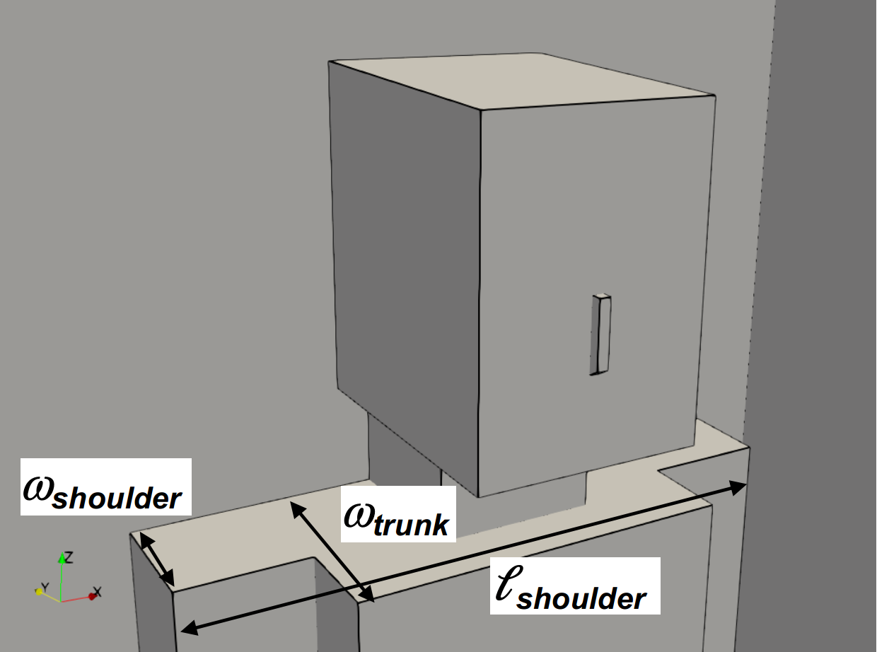
Depending the weight profile of the human, the length between shoulders, the width of the trunk and the width of the shoulders are defined as in Tale 5.1. See Figure 5.1(a) to visualise what these dimensions mean.
| Weight profile | |||
|---|---|---|---|
| Thin | |||
| Normal | |||
| Fat |
5.2 Human characteristics
Humans are divided into 10 parts: Head, Neck, Arms, Forearms, Hands, Trunk, Pelvis, Thighs, Legs and Feet. At the beginning of IGG_Humans.dat, the user can decide to represent only some part of the body if wanted.
Humans can have 3 different activities Activity: Standing, Sitting or Lying. It is mandatory to specify the human activity to each human defined in IGG_Humans.dat.
5.2.1 General options
Whatever the human activity, the user can specify several optional characteristics such as:
-
•
The human height (keyword: Height): float in centimetres. By default 170 is used.
-
•
The human weight profile (keyword: Weight): Thin, Normal or Fat. By default Normal is used.
-
•
The human forearms position (keyword: Forearm): Up or Down. By default Down is used.
-
•
The nose model (keyword: NoseModel): T or F. By default F is used.
-
•
The mouth model (keyword: MouthModel): T or F. By default F is used.
-
•
The mouth area (keyword: MouthArea): float in or Auto. By default the mouth area is 1.18 . If MouthArea is specified but not MouthModel, then MouthModel is set to T.
-
•
The nose area (keyword: NoseArea): float in or Auto. By default the nose area is 0.65 . If NoseArea is specified but not NoseModel, then NoseModel is set to T.
-
•
The nose angle (keyword: NoseAngle): float in degree or Auto. By default the nose angle is . If NoseAngle is specified but not NoseModel, then NoseModel is set to T.
-
•
The body part releasing heat (keyword: HeatingPart): All, Head, Neck, Arms, Forearms, Hands, Trunk, Pelvis, Thighs, Legs and/or Feet. By default All is used.
Remark: The keywords can be used in any order, there is no specific order.
5.2.2 Standing
If the Activity is Standing, then the following is mandatory:
-
•
The face direction (keyword: FaceDirection) of the human, i.e. which surface of the domain the human is looking: South, North, East or West.
-
•
The location, i.e. centre, of the human (keyword: Centre): a 3-tuple of float .
In the case the human is standing on a furniture, then the following is needed:
-
•
The furniture on which the human is standing (keyword: Furniture): an integer corresponding to the ID of the furniture as it appears in IGG_Furniture.dat. In this case, provided by the keywork Centre is ignored.
5.2.3 Sitting
If the Activity is Sitting, then the following is mandatory:
-
•
The furniture on which the human is sit (keyword: Furniture): an integer corresponding to the ID of the furniture as it appears in IGG_Furniture.dat.
-
•
If the furniture is not a Chair or a Seat, then the face direction of the human (keyword: FaceDirection) is mandatory too, i.e. which surface of the domain the human is looking: South, North, East or West.
Remark: When a human is sitting on a Chair or a Seat: the back of the human always touches the back of the seat; if the human is too tall and its feet are going under the ground, then the legs are shorten to touch perfectly the ground; if the human is too short and its thighs are not long enough compare to the seat size, then the thighs are elongated to fit the seat.
5.2.4 Lying
If the Activity is Lying, then the following is mandatory:
-
•
The furniture on which the human is lying (keyword: Furniture): an integer corresponding to the ID of the furniture as it appears in IGG_Furniture.dat.
-
•
The face direction of the human (keyword: FaceDirection), i.e. which surface of the domain the human is looking: South, North, East, West or Ceiling.
-
•
The lying position (keyword: LyingPosition) of the human, i.e. towards which surface of the domain the human head is: South, North, East or West.
Remark: When a human are lying on one side , i.e FaceDirection not being Ceiling, the arm, forearm and hand of this side are not modelled in order to have the human perfectly lying on the mattress.
5.3 Physical IDs
Body part (except mouths and noses) physical IDs have the form ”9xyz” where::
-
•
”x”:: human ID
-
•
”y”:: body part ID: 0: head; 1: neck; 2: arms; 3: forearms; 4: hands; 5: trunk; 6: pelvis; 7: thighs; 8: legs; 9: feet
-
•
”z”:: 1 for ”heat” BCs; 2 for ”no heat” BCs
Mouths and noses physical IDs have the form ”8xyz” where::
-
•
”x”:: human ID
-
•
”y”:: body part ID: 0: mouth; 1: nose
-
•
”z”:: 1 for ”exit” BCs; 2 for ”other” BCs
Ex: ”9201” is human 2 head generating heat; ”8111” is human 1 exit of nose. ”92142” refers to the non-heating hands of human 21. NB: ”8x02” does not exist - mouth is a surface and is an exit only.
Chapter 6 Mesh size constraints
The input file IGG_Mesh.dat (see Code 1) allows the user to specify the mesh characteristics.
-
•
General mesh sizes is firstly defined. NMinElement is the minimum number of elements on one surface. MinLength and MaxLength are the minimum and maximum edge length of the mesh, respectively.
-
•
Constraints can be added to the mesh. First, the number of constraints is defined. In Code 1, 7 constraints are specified by the user for example. Then the constraints are defined. See Section 6 for more details.
-
–
Feature-specific constraint: the feature type to refine is specified, then the edge length wanted given.
-
–
Non-feature-specific constraint: the user can refined/coarsen the mesh in some areas if wanted. The area to be refined/coarsen can be defined by a box or a sphere.
-
–
The mesh can refined locally by the user. The user can also decide to refine specific part of some features.
6.1 Refinement of rectangular boxes
The following features are 2D features or one single rectangular boxes and will be always refined/coarsen everywhere - the option All should always be specified and is the only one supported by IGG:
-
•
Box
-
•
Normal Shelf
-
•
Manual Till
-
•
Separator
-
•
Computer Tower
-
•
Inlet of ventilation
-
•
Outlet of ventilation
-
•
Windows
-
•
Doors
-
•
Diffusers
-
•
Extractors
6.2 Refinement of complex objects
The following features can be refined/coarsen in some part:
-
•
Refrigerated Shelf, Automatic Till, Seat
-
–
All: refine the whole feature
-
–
Lower: the smallest, i.e. lower, part of the L-shape
-
–
Upper: the tallest, i.e. upper, part of the L-shape.
-
–
-
•
Table, Stool
-
–
All: refine the whole feature
-
–
Top: the top, i.e. upper, part of the feature
-
–
Legs: the four legs of the feature.
-
–
-
•
Chair
-
–
All: refine the whole feature
-
–
Seat: the seat part of the chair
-
–
Legs: the four legs of the chair.
-
–
Back: the back part of the chair.
-
–
-
•
Bed: note that constraining upper and lower legs is equivalent to constraint the whole bed…
-
–
All: refine the whole feature
-
–
Mattress: the mattress part of the bed
-
–
Legs: the four upper and lower legs of the bed.
-
–
Laths: the laths upper part of the bed.
-
–
The rectangular box defining the domain can also be refined using the following keywords:
-
•
All: refine all the surfaces of the domain
-
•
Bottom: refine the Bottom surface of the domain
-
•
Top: refine the Top surface of the domain
-
•
East: refine the East surface of the domain
-
•
West: refine the West surface of the domain
-
•
South: refine the South surface of the domain
-
•
North: refine the North surface of the domain
Humans can be also refined/coarsen. The keywords can be All or any specific part of the body. Note that for the arms, forearms, thighs, hands, legs and feet, the keywords need to be in singular form. In short, the keywords are: All, Head, Mouth, Nose, Neck, Trunk, Pelvis, Arm, Forearm, Hand, Thigh, Leg, Foot.
6.3 Refinement in the volume
The user can refined/coarsen the mesh in some areas within the domain volume if wanted. The area to be refined/coarsen can be defined by a box or a sphere. To refine in a box (keyword: Box) area: the user needs to define the centre of the box , , and its size , , . To refine in a sphere (keyword: Sphere) area: the user needs to define the centre of the sphere , , and the radius .
Chapter 7 Physical IDs for Boundary Conditions
Assuming that the File Name defined in IGG_Numerics.dat is MyGeom, MyGeom_PhysicalIDs.dat summarises the Physical IDs assigned to surfaces. These Physical IDs are needed by Fluidity to apply boundary conditions. In the first part of the file, the Physical IDs by feature types (furniture, accessories, humans…) are summaries. In a second part of the file, an attempt is done to group the Physical IDs by boundary conditions types, i.e. walls, heating, inlet, outlet, heat generation… The Physical IDs are grouped by common boundary conditions used in CFD - but the user can decide to use different boundary conditions than the ones suggested if wanted.
7.1 Physical IDs summary
7.1.1 Features
The physical surface IDs are:
-
•
1: Domain surface South
-
•
2: Domain surface East
-
•
3: Domain surface North
-
•
4: Domain surface West
-
•
5: Domain surface Bottom
-
•
6: Domain surface Top
-
•
The physical IDs of 2D features have the form xyy, where:
-
–
x is the integer:
-
*
1 for an inlet
-
*
2 for an outlet
-
*
3 for a door
-
*
4 for a window
-
*
-
–
yy is an integer referring to the feature number from 01 to 99 as defined in IGG_Domain.dat.
-
–
-
•
40: Generic Box
-
•
30: Normal Shelf
-
•
311: Refrigerated shelf cold surfaces
-
•
312: Refrigerated shelf other surfaces
-
•
32: Manual Till
-
•
33: Automatic Till
-
•
341: Table top surface
-
•
342: Table other surfaces
-
•
351: Chair in-contact w/ people surfaces
-
•
352: Chair other surfaces
-
•
361: Seat in-contact w/ people surfaces
-
•
362: Seat other surfaces
-
•
371: Stool top surface
-
•
372: Stool other surfaces
-
•
381: Bed mattress top surface
-
•
382: Bed other surfaces
-
•
39x: Bevel x=bevel ID
-
•
20: Separator
-
•
601: Laptop hot surfaces
-
•
602: Laptop other surfaces
-
•
611: Screen hot surfaces
-
•
622: Screen other surfaces
-
•
621: Computer Tower
-
•
631: Diffuser releasing air towards South
-
•
632: Diffuser releasing air towards East
-
•
633: Diffuser releasing air towards North
-
•
634: Diffuser releasing air towards West
-
•
641: Extractor extracting air towards South
-
•
642: Extractor extracting air towards East
-
•
643: Extractor extracting air towards North
-
•
644: Extractor extracting air towards West
7.1.2 Human
Body part (except mouths and noses) physical IDs have the form ”9xyz” where::
-
•
”x”:: human ID
-
•
”y”:: body part ID: 0: head; 1: neck; 2: arms; 3: forearms; 4: hands; 5: trunk; 6: pelvis; 7: thighs; 8: legs; 9: feet
-
•
”z”:: 1 for ”heat” BCs; 2 for ”no heat” BCs
Mouths and noses physical IDs have the form ”8xyz” where::
-
•
”x”:: human ID
-
•
”y”:: body part ID: 0: mouth; 1: nose
-
•
”z”:: 1 for ”exit” BCs; 2 for ”other” BCs
Ex: ”9201” is human 2 head generating heat; ”8111” is human 1 exit of nose. ”92142” refers to the non-heating hands of human 21. NB: ”8x02” does not exist - mouth is a surface and is an exit only.
7.2 Boundary Conditions
Boundary conditions suggested are as follows:
-
•
For Velocity/Pressure:
-
–
No Slip/Slip (walls)
-
–
Inlets
-
–
Outlets
-
–
Doors
-
–
Windows
-
–
Diffuser
-
–
Extractor
-
–
-
•
For Temperature/Tracer
-
–
Heat flux (for human, screen…)
-
–
Adiabatic
-
–
Fixed temperature (for refrigerated shelves for ex.)
-
–
Acknowledgements
This work is supported by the EPSRC Grand Challenge grant ‘Managing Air for Green Inner Cities (MAGIC) EP/N010221/1; EPSRC RELIANT, Risk EvaLuatIon fAst iNtel-ligent Tool for COVID19 (EP/V036777/1); EPSRC INHALE, Health assessment across biological length scales (EP/T003189/1); CO-TRACE COvid-19 Transmission Risk Assessment Case studies - Education Establishments EP/W001411/1; PROTECT COVID-19 National Core Study on transmission and environment and . This work has been undertaken,in part, as a contribution to ‘Rapid Assistance in Modelling the Pandemic’ (RAMP), initiated by the Royal Society. TRACK…
Bibliography
- [1] Imperial College London AMCG. Fluidity manual v4.1.12. Imperial College London, 4 2015.