Observation of helimagnetism in the candidate ferroelectric CrI2
Abstract
CrI2 is a quasi-one dimensional (1D) van der Waals (vdW) system that exhibits helimagnetism that propagates along the ribbons. This was determined from neutron time-of-flight diffraction measurements. Below K, a screw-like helimagnetic order develops with an incommensurate wavevector of at 8 K. Using density functional theory (DFT) calculations, the - model was leveraged to describe the helimagnetism, where and correspond, respectively, to a ferromagnetic nearest neighbor (NN) and antiferromagnetic next-nearest neighbor (NNN) intrachain interaction. The DFT calculations predict that bulk CrI2 in the orthorhombic crystal structure satisfies the condition, which favors formation of helimagnetic order.
I Introduction
Van der Waals (vdW) layered materials have a broad range of potential applications, especially when magnetic order can be manipulated McGuire (2020). Efforts in this direction surged after reports of ferromagnetic (FM) order in monolayer CrI3 Huang et al. (2017), antiferromagnetic (AFM) order in monolayer FePS3 Lee et al. (2016); Wang et al. (2016), and the discovery that CrI3 can be AFM or FM depending on layer stacking Huang et al. (2020); Schneeloch et al. (2023). One vdW-layered magnetic material, CrI2, has received little attention even thought its quasi-one dimensional (1D) structure offers a new view into the nature of exchange interactions in vdW heterostructures.
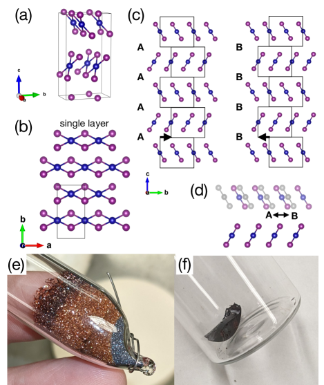
CrI2 has two polytypes with the same intralayer structure: a monoclinic phase, where the layers are oriented in the same direction Tracy et al. (1962a), and an orthorhombic phase, where the layers are oriented in alternating directions Guen et al. (1972); Besrest and Jaulmes (1973); Guen et al. (1976); Guen and Nguyen-Huy-Dung (1976), the latter being reminiscent of the phase of MoTe2 or WTe2 Clarke et al. (1978). The intralayer structure consists of a triangular lattice of Cr2+ ions, each surrounded by six I- ions in an octahedral configuration, but with a Jahn-Teller (JT) distortion Besrest and Jaulmes (1973) lengthening two of these bonds so that edge-sharing octahedra form “ribbon chains” along the -axis (Fig. 1(a,b)). The JT distortion induces a similar ribbon-chain structure in many other compounds, including CuBr2 Oeckler and Simon (2000) and CuCl2 Wells (1947), which are isostructural to monoclinic CrI2, as well as CrBr2 (which has a different layer stacking) Tracy et al. (1962b), CrCl2 (in which the ribbon chains do not form CrI2-like layers) Tracy et al. (1961) and -PdCl2 Wells (1939); Evers et al. (2010).
The magnetic properties of CrI2 are largely unexplored, with the sole attempt, to our knowledge, being a Mössbauer spectroscopy study indicating a magnetic splitting of spectral lines at 4.2 K, but not at 77 K Djermouni (1976); a transition at 45(2) K was claimed, but without supporting data, and magnetic susceptibility was attempted but deemed inconclusive due to suspected contamination from the ferromagnetic CrI3. Despite the paucity of bulk experimental studies of CrI2, there have been three recent studies on monolayers synthesized by molecular beam epitaxy Cai et al. (2021); Peng et al. (2020); Li et al. (2023), with scanning tunneling spectroscopy showing band gaps of about 3.0 to 3.2 eV Cai et al. (2021); Peng et al. (2020). Several recent theoretical studies have also been reported Kulish and Huang (2017); Zhang et al. (2020); Zhao et al. (2021); Yang et al. (2022); Zhang et al. (2022), focusing mainly on the monolayer. In calculations, both ferromagnetic (FM) Peng et al. (2020) and antiferromagnetic (AFM) Zhang et al. (2022) orders result in the lowest free energy, though incommensurate ordering was not considered. Recent reports suggested that the orthorhombic phase has an out-of-plane polarization that can be reversed by sliding the layers Zhang et al. (2022), where such multiferroic behavior could lead to significant technological applications. Thus, there is a clear need for experimental measurements to clarify the magnetic structure of this compound.
We report time-of-flight neutron diffraction measurements on a predominantly orthorhombic CrI2 powder sample. Helimagnetic order is observed with a modulation wavevector arising below K with at 8 K and decreasing slightly on warming. DFT calculations were performed to extract the exchange interactions, resulting in a sizable next-nearest-neighbor AFM intrachain coupling that suggests an origin for the helimagnetic ordering.
II Methods
II.1 Experimental Details
CrI2 powder was synthesized by sealing a stoichiometric mixture of fine (-200 mesh) chromium powder and iodine pieces in ampoules and heating to 650 ∘C within a day, then heated at 650 ∘C or 750 ∘C for several days before furnace-cooling. Below 600 ∘C, CrI3 forms instead, and an ampoule heated at 600 ∘C in a vertical tube furnace showed a sharp divide between silvery CrI3 and red CrI2 powder (Fig. 1(e)), due to CrI3 forming in the cooler region of the temperature gradient. For the single crystals used for the magnetic susceptibility, CrI2 crystals were grown from a melt by heating an ampoule with a stoichiometric mixture of Cr and I up to 900 ∘C (after dwelling at 650 ∘C for a day to make sure the iodine had fully reacted with the chromium powder), then furnace-cooled to 750 ∘C before quenching in water. Slow cooling from 900 ∘C to 750 ∘C resulted in larger crystals, such as the 0.5 g piece shown in Fig. 1(f). CrI2 is hygroscopic, and crystals disintegrate within minutes in humid air, though they can be stored in dry air for weeks without visible deterioration. Neutron diffraction experiments were performed on the POWGEN diffractometer at the Spallation Neutron Source of Oak Ridge National Laboratory Huq et al. (2019). The powder was loaded into a vanadium can in a helium glovebox before measurement. A POWGEN automatic changer was adopted as the sample environment. Two neutron banks with center wavelengths of 1.5 Å and 2.665 Å were used for the data collection. Refinement was done using calculations in which the diffuse scattering was obtained from the formalism of Ref. Treacy et al. (1991); the software GSAS-II Toby and Von Dreele (2013) was used to obtain lattice parameters. Single crystal X-ray measurements were also carried out as a function of temperature, with data refined using the software APEX4 by Bruker.
II.2 Density functional theory
First-principles calculations were performed based on density functional theory (DFT) as implemented in the open-source plane-wave pseudopotential code, Quantum ESPRESSO Giannozzi et al. (2009, 2017). We chose the generalized gradient approximation (GGA) and PBEsol exchange-correlation functional for all ground-state calculations Perdew et al. (1996, 2008). A DFT approach with a Hubbard eV Zhao et al. (2021) was applied on the Cr- orbitals to account for the correlated orbital effects Anisimov et al. (1991); Solovyev et al. (1994). The kinetic energy cutoff was set to 70 Ry for the wavefunctions, and the Brillouin zone was sampled using a -centered Monkhorst-Pack -mesh for all calculations Monkhorst and Pack (1976). Semiempirical Grimme DFT-D3 vdW dispersion correction approach with three-body contribution was also applied to treat the vdW bonding in the CrI2 crystal Grimme et al. (2010). We used the orthorhombic crystal structure (space group # 36, ) for our DFT calculation. In this space group, there are two unique crystallographic sites for the I atoms, whereas there is only one unique site for the Cr atoms. All atoms occupy the Wyckoff site labelled “4a”. We performed full crystal structure relaxation (with and without the vdW dispersion correction) where both the unit cell parameters and atomic coordinates are relaxed. Convergence thresholds for the maximum residual force and maximum energy difference between consecutive iterations were set at less than a.u. and Ry, respectively. Representative unit cells of DFT relaxed CrI2 crystal structures are given in Fig. S4. The atomic parameters of the DFT relaxed crystal structures with and without the vdW dispersion correction are in the CIF files included in the Supplemental Information. The DFT calculated absolute Cr magnetic moment is determined to be 3.79.
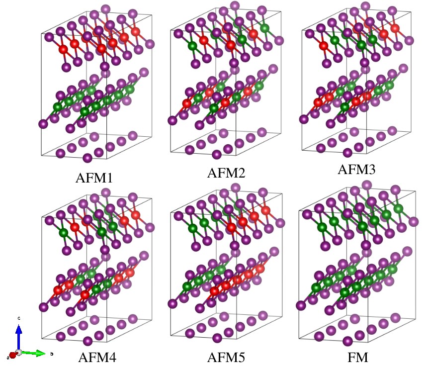
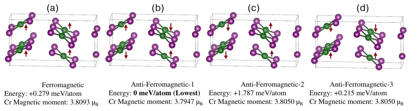
We employed the methodology introduced by Banks et al. Banks et al. (2009) to compute the spin-exchange parameters, . We constructed a 411 supercell and considered six independent collinear spin arrangements [one ferromagnetic (FM) and five antiferromagnetic (AFM), which are shown in Fig. S5]. We then performed self-consistent field calculations using a -centered -mesh of . The total energy data, along with the Heisenberg Hamiltonian, used to calculate each from the supercell is given in subsection VI.6 in the Supplemental Material.
III Results
III.1 Single-crystal X-ray diffraction
| 100 K | 200 K | 300 K | 400 K | |
|---|---|---|---|---|
| (Å) | 3.9070(5) | 3.9158(3) | 3.9195(3) | 3.9214(4) |
| (Å) | 7.4963(17) | 7.5366(8) | 7.5722(6) | 7.6110(10) |
| (Å) | 13.479(3) | 13.5142(13) | 13.5618(10) | 13.6092(17) |
| x | y | z | ||
|---|---|---|---|---|
| 100 K | ||||
| I1 | 0 | 0.2045(3) | 0.37815(17) | 0.0108(8) |
| I2 | 0 | 0.4720(3) | 0.62193(11) | 0.0115(8) |
| Cr1 | 0.5 | 0.3377(9) | 0.4987(6) | 0.0128(14) |
| 200 K | ||||
| I1 | 0 | 0.20577(8) | 0.37850(4) | 0.01277(17) |
| I2 | 0 | 0.47094(8) | 0.62147(3) | 0.01374(18) |
| Cr1 | 0.5 | 0.3379(3) | 0.49992(15) | 0.0156(3) |
| 300 K | ||||
| I1 | 0 | 0.20706(10) | 0.37872(5) | 0.01927(19) |
| I2 | 0 | 0.47003(9) | 0.62127(3) | 0.02039(19) |
| Cr1 | 0.5 | 0.3383(3) | 0.49975(17) | 0.0227(4) |
| 400 K | ||||
| I1 | 0 | 0.20813(16) | 0.37891(8) | 0.0270(3) |
| I2 | 0 | 0.46917(16) | 0.62096(5) | 0.0279(3) |
| Cr1 | 0.5 | 0.3378(5) | 0.5000(3) | 0.0309(7) |
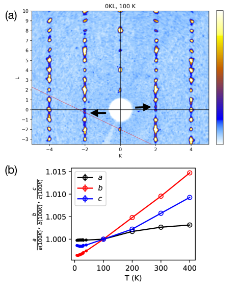
Single-crystal X-ray diffraction (SCXRD) on a vapor-tranport grown crystal was performed as a function of temperature. An intensity plot in the scattering plane at 100 K is shown in Fig. 2(a). The refined lattice and atomic parameters are shown in Tables 1 and 2, respectively. From Fig. 2(a), not only is the main (orthorhombic) phase observed, but also a secondary, co-aligned phase with the monoclinic structure Tracy et al. (1962a) (with two of its Bragg peaks indicated by arrows), as well as diffuse scattering streaks indicating some degree of stacking disorder. No sign of a structural phase transition was observed from 100 to 400 K. A crystal from a melt-grown batch was also measured by SCXRD, and verified to have the orthorhombic structure. The temperature dependence of the lattice parameters (from the SCXRD and neutron diffraction data) are plotted in Fig. 2(b). The thermal expansion is smallest along the -axis, which is as expected given the stronger bonding along the chains (as seen in structurally similar CuCl2 Banks et al. (2009).)
III.2 Powder neutron diffraction
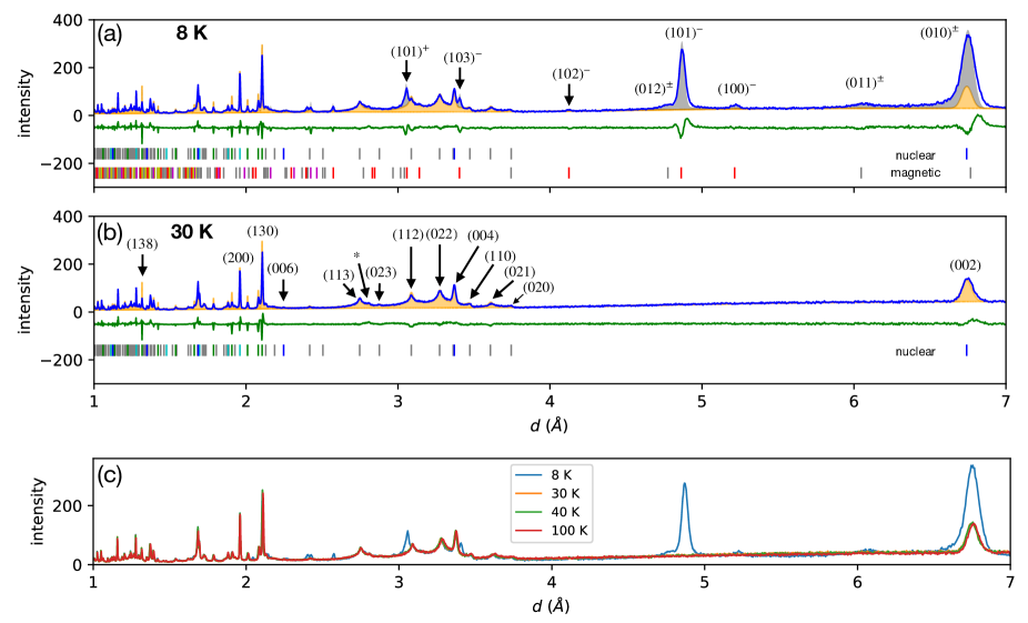
Fig. 3(a,b) is a plot of the neutron diffraction data collected at two temperatures, 8 and 30 K. A substantial amount of diffuse scattering arising from stacking disorder is observed, which is accounted for in the calculated curves and will be discussed below. Selected nuclear and magnetic Bragg peaks are labeled in Fig. 3(a,b); a more comprehensive indexing can be found in Fig. S1 of the Supplemental Materials, along with the expected intensity in the absence of stacking disorder. At 30 K, almost every peak can be indexed by the orthorhombic (ortho-CrI2) structure Besrest and Jaulmes (1973). Only one small peak above Å (at Å) is inconsistent with the ortho-CrI2 structure; this peak is likely the peak of the monoclinic CrI2 polytype Tracy et al. (1962a), which would imply a volume ratio of about 1% relative to the orthorhombic phase, assuming no monoclinic-phase stacking disorder. Little change in intensity is seen from 30 to 40 K or 100 K (Fig. 3(c).) No sign of CrI3 was observed, in either the or phases Schneeloch et al. (2023). Some preferred orientation was present, as seen in the ratio of peaks such as and (), whose intensities would be immune to stacking disorder. We found a March-Dollase ratio of 1.15 to be satisfactory in our calculations Dollase (1986).
The diffuse scattering arises from a disordered sequence of the two stacking options present in the orthorhombic CrI2 crystal structure (Fig. 1(c,d).) Using the same notation as for similar stacking variations seen in Mo1-xWxTe2 Schneeloch et al. (2020), we can construct one ortho-CrI2 twin by a repeated “A”-type stacking operation. Since each layer has approximate inversion symmetry, an inversion operation keeps the intralayer structure largely unchanged but changes the layer stacking from A-type to “B”-type, related by alternating -axis translations of about 0.344 lattice units. Calculations of the diffuse scattering were performed using the formalism of Ref. Treacy et al. (1991), which is the basis for the software DIFFaX; see the Supplementary Materials for mathematical details. For our data, we find satisfactory agreement if we assume the intensity is the sum of two contributions with 22% of (nearly-ordered) and 78% of (random) , where is the probability of switching stacking types (A- or B-type) between consecutive layers. Certain peaks are expected to be unaffected by stacking disorder, in particular, where is a small multiple of 3. This invariance is due to the stacking translations randomly contributing phases of to terms in the summation of the structure factor, which are about unity when is a small multiple of 3. The peaks are certainly prominent in our data. The peaks, though, while prominent, are substantially weaker than expected from our calculations (e.g., (138) in Fig. 3(b).) A likely possibility is the presence of additional types of stacking, such as those in monoclinic CrI2 Tracy et al. (1962a) or CrBr2 Tracy et al. (1962b); preliminary calculations suggest that such stacking may be (randomly) present on the order of 10-20%, but an in-depth calculation is beyond the scope of this paper.
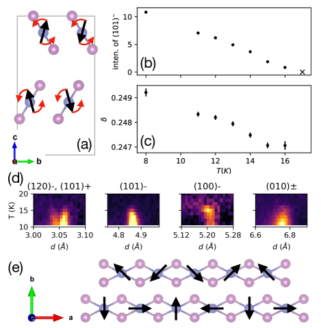
Below 17 K, magnetic satellite peaks appear at . The peaks are labeled , , or . Their position is consistent with a spin spiral propagating along the ribbon chains, with the “untwisted” spin orientation (i.e., without the helimagnetic 90∘ rotation between neighboring Cr2+ ions) depicted in Fig. 4(a). The magnetic peaks are affected by stacking disorder in the same way as the nuclear peaks, i.e., peaks with remain prominent, peaks with are diminished relative to calculations but still prominent, and the remaining peaks are typically greatly broadened. The similar broadening for nuclear and magnetic peaks suggests that only the locations of the spins are disordered (due to random stacking translations), while disorder in the orientation of the spins is not needed to explain our data.
While magnetic ordering increases on cooling, the ordered magnetic moment is not close to saturation down to 8 K, as seen from the intensity of the magnetic peak in Fig. 4(b). A refinement (see Supplemental Materials for details) resulted in an ordered magnetic moment of 2.95(10) /Cr2+ ion. This value is well short of the 4 /Cr2+ expected for the high-spin Cr2+ values of and . The magnitude of the modulation vector is plotted in Fig. 4(c); was obtained by fitting the positions of the , , , , , and peaks, all but which should be unaffected by stacking disorder. Though , the modulation vector is incommensurate, with decreasing from 0.2492 to 0.2470 on warming from 8 to 16 K. These values correspond to rotations of spins between consecutive Cr2+ ions along the ribbon chains of 89.7∘ and 88.9∘.
The magnetic intensity agrees best with the data if we assume that the “untwisted” spin structure (i.e., without the helical twist, as in Fig. 4(a)) is AFM within the plane, and nearly FM but with an alternating tilt of between the layers. The absence of the (002)± magnetic peak (which would be near Å) is consistent with the untwisted spins within each layer being coaligned, since their contributions would then cancel out (see Eq. 3 in the Supplemental Materials.) At the same time, there is a small peak near Å, which would be absent if the untwisted spins were collinear between the layers. The rotation plane of the spin helix is likely (i.e., screw-like rather than cycloidal Tokura et al. (2014)), since that matches our data much better than or , the other plausible alternatives given the symmetry of orthorhombic CrI2; see Supplemental Materials for a comparison. With unpolarized neutrons, we are unable to tell the handedness of the helical rotation; presumably, domains with both chiralities are present. Our spin structure bears a resemblance to that predicted by the authors of Ref. Zhang et al. (2022), although the helical modulation was not in their proposed structure.
What effect does the stacking disorder have on the magnetic order? On the one hand, we expect significant interlayer coupling, as was seen for structurally similar CrI3 (with a value of meV for the summed exchange constants for interlayer bonding for the phase Chen et al. (2021)). Our DFT calculations (to be discussed below) also suggest a sizable interlayer magnetic coupling. However, for symmetry reasons, we expect the magnetic ordering to be largely unaffected by the A/B stacking disorder. If we apply an inversion operation to one twin of the structure, which we call “AA” to denote its A-type stacking, we end up with the “BB” twin. However, spin is a pseudovector, and does not change its orientation upon inversion, so the same spin structure that exists for the AA twin should be valid for the BB twin. Thus, assuming that magnetic interactions beyond nearest neighboring layers are negligible, the relative spin orientation of neighboring layers should be independent of A- or B-type stacking, and no disorder in the orientation of the magnetic moments should arise from the A/B stacking disorder. This situation is different from that in CrI3, where the different types of stacking (monoclinic and rhombohedral) are not symmetry-equivalent to each other, and a stacking dependence of the spin orientation is observed Schneeloch et al. (2023). We note, though, that partial layer sliding, such as during coherent phonon oscillations produced in ultrafast pump-probe spectroscopy Weber (2021), would modulate the interlayer magnetic coupling, and thus the relative phase of the spin helices of neighboring layers.
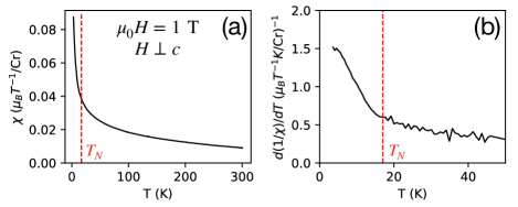
III.3 Magnetic susceptibility
The onset of helimagnetic order can also be inferred from magnetization data taken on melt-grown crystals, suggesting that the magnetic transition is, at most, weakly affected by stacking disorder. The magnetization has a monotonic increase on cooling (Fig. 5(a).) This behavior contrasts with the broad hump often seen in quasi-1-dimensional magnetic systems, with the most relevant examples being CrCl2 Hagiwara and Katsumata (1995), CuCl2 Banks et al. (2009), and CuBr2 Zhao et al. (2012); Lee et al. (2012), suggesting the role of stronger inter-layer and inter-chain interactions in CrI2. The inverse magnetization is roughly linear above K, with a fit resulting in a Curie-Weiss temperature of about -70 K (see Fig. S3(a) in the Supplemental Materials), suggesting the dominance of antiferromagnetic interactions. Below , though, the derivative shows a marked upturn, indicating the onset of helimagnetic ordering (Fig. 5(b).) Magnetization vs. field at 3 K (Fig. S3(b)) shows linear and non-hysteretic behavior at low fields, with a possible transition induced by fields above 3 T. Generally, we saw similar behavior for magnetic field applied in-plane or out-of-plane, but further study is needed to determine the extent to which in-plane anisotropy is present, i.e., along or perpendicular to the ribbon chains.
| Relaxation procedure | Cr-Cr (Å) | (meV) |
|---|---|---|
| 3.930 | =2.99 | |
| 7.861 | =2.19 | |
| DFT++vdW relaxed | 4.196 | =0.42 |
| 7.017 | =2.11 | |
| 6.965 | =0.03 | |
| 3.947 | =3.55 | |
| 7.894 | =2.14 | |
| DFT+ relaxed | 4.279 | =0.27 |
| 7.195 | =1.36 | |
| 7.033 | =0.03 |
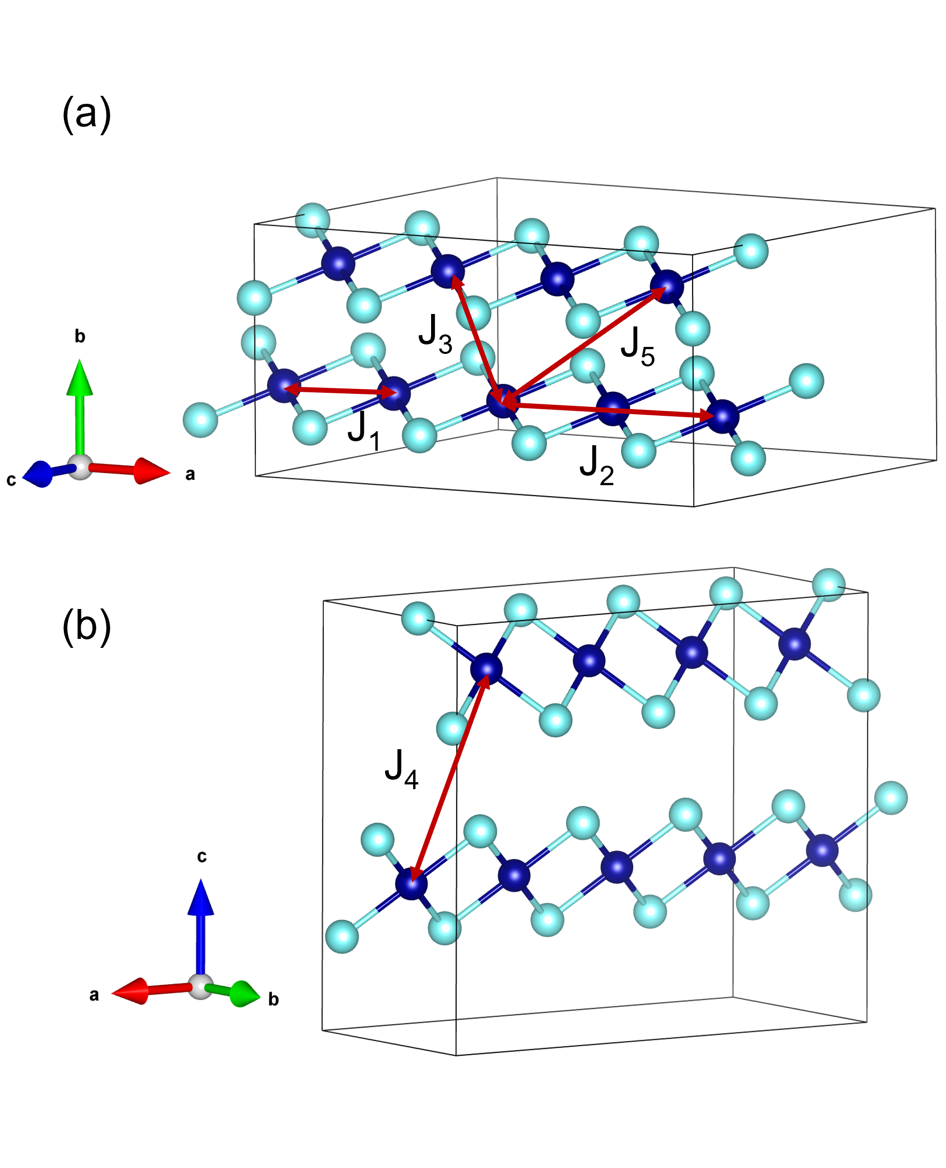
To determine whether or not the helimagnetism of CrI2 has a similar origin as for the intrachain frustrated magnetic interactions in CuX2 (X=Cl, Br), we performed DFT calculations using crystal structures that were relaxed with and without the vdW dispersion correction. We computed the energies of a number of collinear spin configurations, then mapped their relative energies to the following spin Hamiltonian,
| (1) |
to obtain the exchange interactions (our definition of – is shown in Fig. 6.) In terms of differences in the DFT relaxed crystal structures, introduction of vdW dispersion correction has an impact on the unit cell volume. The crystal structure with vdW correction had a smaller unit cell volume (385 Å3) when compared to the crystal structure without the vdW dispersion correction (404 Å3). As a result, introduction of vdW correction reduced the Cr-Cr bond lengths leading to closer intrachain and interlayers bond distances (see Table 3).
The DFT derived exchange interactions for coordinates relaxed with or without the vdW correction are shown in Table 3. The total energy difference data used for the calculation of is given in Table S1. As shown in Fig. 6, the terms and correspond to exchange energies that arise due to the nearest- and next-nearest-neighbor intrachain Cr-Cr bonds. According to the - model Blundell (2001), the necessary condition for helimagnetism is . From Table 3, our DFT calculated and satisfies the - model condition (irrespective of the choice of crystal structure), which supports the formation of helimagnetism in CrI2 crystals. We attribute this to the sizable AFM next-nearest-neighbor intrachain interaction term. We also infer from the magnitude of that the inter-layer magnetic coupling is non-negligible and cannot be ignored. For the intralayer-interchain interactions, the nearest- and next-nearest-neighbor Cr-Cr bonds correspond to and , respectively, and they are smaller than that of the , and parameters.
IV Discussion
There are striking similarities in both the structure and magnetism between CrI2 and CuX2 (X=Cl, Br), as well as many other Cu2+ ribbon-chain compounds. Aside from differences in layer stacking, CuX2 (X=Cl, Br) is isostructural to CrX2 (X=Br, I), with JT distortions of the Cu2+X and Cr2+X octahedra resulting in ribbon-chain structures. Helimagnetic order has been reported in CuCl2 below 24 K Banks et al. (2009), and in CuBr2 below 73.5 K Zhao et al. (2012), with both exhibiting 90∘ rotations of spins along the chain axis between consecutive Cu/Cr ions (specifically, 81∘ for CuCl2 and 85∘ for CuBr2), and an antiferromagnetism between intralayer chains similar to CrI2. One difference, though, is the plane of the helical rotation; CuCl2 and CuBr2 are reported to have spins rotate cycloidally within the plane that includes the chain and out-of-plane directions, whereas the spins in orthorhombic CrI2 appear to rotate perpendicular to the chain. A number of other Cu2+ ribbon-chain compounds also exhibit helimagnetism, such as LiCuVO4 Enderle et al. (2005); Gibson et al. (2004), LiCu2O2 Masuda et al. (2004), NaCuMoO4(OH) Asai et al. (2020), and PbCuSO4(OH)2 Willenberg et al. (2012). The helimagnetism is often described in terms of the - model. It is frequently assumed that the helimagnetism in the Cu2+ ribbon chain compounds arises from the frustration between an AFM and a sufficiently weak , though there are disagreements as to whether the - model can fully explain the magnetism or where different materials fall in regards to the size of the ratio. While there has been plenty of research into the helimagnetism of Cu2+ compounds, few such studies have been done of their Cr2+ counterparts. (CrCl2 is an exception; though collinear AFM ordering sets in below 16 K Cable et al. (1960) or 11.3 K Winkelmann et al. (1997), depending on the polymorph, intriguingly, short-range helimagnetic order has been reported Winkelmann et al. (1997), with a 97∘ rotation angle between neighboring spins.) The case of CrI2 suggests a similarity in the magnetism of Cr2+ and Cu2+ ribbon chain compounds that should be explored further.
A better understanding of the connection between the helimagnetism and ribbon-chain structure of CrI2 could be achieved by 1) measuring the magnetic behavior of CrBr2, which is, thus far, unreported, 2) performing a more detailed study on the short-range helimagnetism of CrCl2, and 3) conducting inelastic neutron scattering measurements on CrI2 to validate the exchange interactions between the ions, paired with more in-depth DFT calculations that go beyond collinear spin structures and include the effects of spin-orbit coupling.
The helimagnetism of CrI2 presents a number of opportunities for future research. There is the potential for sliding ferroelectricity in orthorhombic CrI2 by virtue of its layer stacking Zhang et al. (2022), in which the electric polarization may be switchable via layer sliding as has been observed for other bilayer systems such as WTe2 and hexagonal boron nitride Wu and Li (2021). Another research opportunity involves the search for a monolayer helimagnetic multiferroic. NiI2 has recently gained attention for being a potential single-layer multiferroic Song et al. (2022), where the ferroelectricity (FE) is assumed to arise from the helimagnetic ordering Tokura et al. (2014) (though there is controversy as to whether FE has, in fact, been demonstrated Jiang et al. (2023).) We have shown that CrI2 is helimagnetic in the bulk, and isolation of monolayers of CrI2 has already been reported Cai et al. (2021); Li et al. (2023); Peng et al. (2020), so monolayer CrI2 would be a natural candidate for helimagnetism. We should make a couple of points, however. First, while (nearly-isostructural) CuBr2 was reported to have strong magnetoelectric coupling associated with its helimagnetic ordering Zhao et al. (2012), the spin helix is cycloidal in CuBr2 and CrI2, but screw-like in CrI2, and only cycloidal helices are expected to generate a ferroelectric polarization by the inverse Dzyaloshinskii-Moriya mechanism Tokura et al. (2014). However, an applied magnetic field may change the helical plane and allow (or suppress) FE, as has been demonstrated for CuCl2 Seki et al. (2010). Second, the magnetic order for monolayer CrI2 may differ from that of the bulk; the helimagnetism in monolayer NiI2, in fact, has been reported to have a different wavevector than bulk NiI2 Miao et al. (2023). An investigation into the magnetic properties of monolayer CrI2 would, no doubt, enlighten the search for novel magnetic materials in the few-layer limit.
V Conclusion
In conclusion, we observed via neutron diffraction the onset of helimagnetic order below 17 K in orthorhombic CrI2. The spin helix propagates along the chain direction with a wavevector of about at 8 K, decreasing slightly in magnitude on warming. Our DFT calculations provide evidence suggesting that one of the key factors behind the helimagnetism may be a sizable antiferromagnetic next-nearest-neighbor intrachain coupling.
Acknowledgements
The work at the University of Virginia is supported by the Department of Energy, Grant number DE-FG02-01ER45927. A portion of this research used resources at the Spallation Neutron Source, a DOE Office of Science User Facility operated by Oak Ridge National Laboratory. DFT calculations are performed using the Rivanna cluster that is supported and maintained by the University of Virginia research computing.
References
- McGuire (2020) Michael A. McGuire, “Cleavable magnetic materials from van der Waals layered transition metal halides and chalcogenides,” Journal of Applied Physics 128, 110901 (2020).
- Huang et al. (2017) Bevin Huang, Genevieve Clark, Efrén Navarro-Moratalla, Dahlia R. Klein, Ran Cheng, Kyle L. Seyler, Ding Zhong, Emma Schmidgall, Michael A. McGuire, David H. Cobden, Wang Yao, Di Xiao, Pablo Jarillo-Herrero, and Xiaodong Xu, “Layer-dependent ferromagnetism in a van der Waals crystal down to the monolayer limit,” Nature 546, 270–273 (2017).
- Lee et al. (2016) Jae-Ung Lee, Sungmin Lee, Ji Hoon Ryoo, Soonmin Kang, Tae Yun Kim, Pilkwang Kim, Cheol-Hwan Park, Je-Geun Park, and Hyeonsik Cheong, “Ising-Type Magnetic Ordering in Atomically Thin FePS3,” Nano Letters 16, 7433–7438 (2016).
- Wang et al. (2016) Xingzhi Wang, Kezhao Du, Yu Yang Fredrik Liu, Peng Hu, Jun Zhang, Qing Zhang, Man Hon Samuel Owen, Xin Lu, Chee Kwan Gan, Pinaki Sengupta, Christian Kloc, and Qihua Xiong, “Raman spectroscopy of atomically thin two-dimensional magnetic iron phosphorus trisulfide (FePS3) crystals,” 2D Materials 3, 031009 (2016).
- Huang et al. (2020) Bevin Huang, Michael A. McGuire, Andrew F. May, Di Xiao, Pablo Jarillo-Herrero, and Xiaodong Xu, “Emergent phenomena and proximity effects in two-dimensional magnets and heterostructures,” Nature Materials 19, 1276–1289 (2020).
- Schneeloch et al. (2023) John A. Schneeloch, Luke Daemen, and Despina Louca, “Antiferromagnetic-ferromagnetic homostructures with Dirac magnons in van der Waals magnet CrI3,” (2023), arXiv:2305.11750 [cond-mat].
- Momma and Izumi (2011) Koichi Momma and Fujio Izumi, “VESTA 3 for three-dimensional visualization of crystal, volumetric and morphology data,” Journal of Applied Crystallography 44, 1272–1276 (2011).
- Tracy et al. (1962a) J. W. Tracy, N. W. Gregory, J. M. Stewart, and E. C. Lingafelter, “The crystal structure of chromium(II) iodide,” Acta Crystallographica 15, 460–463 (1962a).
- Guen et al. (1972) Luc Guen, Marc Alléaume, Rose Éholié, Jean Flahaut, and Georges Chaudron, “Étude du système chrome-iode,” C. R. Seances Acad. Sci., Ser. C 275, 111–114 (1972).
- Besrest and Jaulmes (1973) F. Besrest and S. Jaulmes, “Structure cristalline de l’iodure de chrome, CrI2,” Acta Crystallographica Section B: Structural Crystallography and Crystal Chemistry 29, 1560–1563 (1973).
- Guen et al. (1976) L. Guen, Huy Dung Nguyen, R. Éholie, and J. Flahaut, “Systèmes CrI2-MI2 (M=Ti, V, Mn, Fe, Co, Ni, Zn) Diagrammes de Phases, étude Structurale Effet Jahn-Teller Coopératif,” Ann. Chim. 1, 39–46 (1976).
- Guen and Nguyen-Huy-Dung (1976) L. Guen and Nguyen-Huy-Dung, “Manganèse(II) Chrome(II) Diiodure: Phase de (Mn,Cr)I2,” Acta Crystallographica Section B: Structural Crystallography and Crystal Chemistry 32, 311–312 (1976).
- Clarke et al. (1978) R. Clarke, E. Marseglia, and H. P. Hughes, “A low-temperature structural phase transition in -MoTe2,” Philosophical Magazine Part B 38, 121–126 (1978).
- Oeckler and Simon (2000) O. Oeckler and A. Simon, “Redetermination of the crystal structure of copper dibromide, CuBr2,” Zeitschrift für Kristallographie - New Crystal Structures 215, 13–13 (2000).
- Wells (1947) A. F. Wells, “333. The crystal structure of anhydrous cupric chloride, and the stereochemistry of the cupric atom,” Journal of the Chemical Society , 1670–1675 (1947).
- Tracy et al. (1962b) J. W. Tracy, N. W. Gregory, and E. C. Lingafelter, “Crystal structure of chromium(II) bromide,” Acta Crystallographica 15, 672–674 (1962b).
- Tracy et al. (1961) J. W. Tracy, N. W. Gregory, E. C. Lingafelter, J. D. Dunitz, H.-C. Mez, R. E. Rundle, C. Scheringer, H. L. Yakel, and M. K. Wilkinson, “The crystal structure of chromium(II) chloride,” Acta Crystallographica 14, 927–929 (1961).
- Wells (1939) A. F. Wells, “The Crystal Structure of Palladous Chloride PdCl2,” Zeitschrift für Kristallographie - Crystalline Materials 100, 189–194 (1939).
- Evers et al. (2010) Jürgen Evers, Wolfgang Beck, Michael Göbel, Stefanie Jakob, Peter Mayer, Gilbert Oehlinger, Marianne Rotter, and Thomas M. Klapötke, “The Structures of -PdCl2 and -PdCl2: Phases with Negative Thermal Expansion in One Direction,” Angewandte Chemie International Edition 49, 5677–5682 (2010).
- Djermouni (1976) Belkacem Djermouni, Structural and magnetic properties of CrI2, CrI3, CsCrI3 and FeSb2O4 from 129I and 121Sb Moessbauer spectroscopy, Ph.D. thesis, L’Université Louis Pasteur de Strasbourg, France (1976), cRN-CNPA–76-14 INIS Reference Number: 8302241.
- Cai et al. (2021) Xinqiang Cai, Zhilin Xu, Shuai-Hua Ji, Na Li, and Xi Chen, “Molecular beam epitaxy growth of iodide thin films,” Chinese Physics B 30, 028102 (2021).
- Peng et al. (2020) Lang Peng, Jianzhou Zhao, Min Cai, Gui-Yuan Hua, Zhen-Yu Liu, Hui-Nan Xia, Yuan Yuan, Wen-Hao Zhang, Gang Xu, Ling-Xiao Zhao, Zeng-Wei Zhu, Tao Xiang, and Ying-Shuang Fu, “Mott phase in a van der Waals transition-metal halide at single-layer limit,” Physical Review Research 2, 023264 (2020).
- Li et al. (2023) Peigen Li, Nanshu Liu, Jihai Zhang, Shenwei Chen, Xuhan Zhou, Donghui Guo, Cong Wang, Wei Ji, and Dingyong Zhong, “Two-Dimensional Magnetic Semiconducting Heterostructures of Single-Layer CrI3–CrI2,” ACS Applied Materials & Interfaces 15, 19574–19581 (2023).
- Kulish and Huang (2017) Vadym V. Kulish and Wei Huang, “Single-layer metal halides MX2 (X = Cl, Br, I): stability and tunable magnetism from first principles and Monte Carlo simulations,” Journal of Materials Chemistry C 5, 8734–8741 (2017).
- Zhang et al. (2020) Jingjing Zhang, Jin Yang, Liangzhong Lin, and JiaJi Zhu, “An antiferromagnetic two-dimensional material: Chromium diiodides monolayer,” Journal of Semiconductors 41, 122502 (2020).
- Zhao et al. (2021) Yuanyuan Zhao, Hongsheng Liu, Junfeng Gao, and Jijun Zhao, “Transition of CrI2 from a two-dimensional network to one-dimensional chain at the monolayer limit,” Physical Chemistry Chemical Physics 23, 25291–25297 (2021).
- Yang et al. (2022) Liu Yang, Yaxin Gao, Menghao Wu, and Puru Jena, “Interfacial triferroicity in monolayer chromium dihalide,” Physical Review B 105, 094101 (2022).
- Zhang et al. (2022) Shuqing Zhang, Fawei Tang, Xiaoyan Song, and Xinping Zhang, “Structural phase transitions and Raman identifications of the layered van der Waals magnet CrI2,” Physical Review B 105, 104105 (2022).
- Huq et al. (2019) A. Huq, M. Kirkham, P. F. Peterson, J. P. Hodges, P. S. Whitfield, K. Page, T. Hűgle, E. B. Iverson, A. Parizzi, and G. Rennich, “POWGEN: rebuild of a third-generation powder diffractometer at the Spallation Neutron Source,” Journal of Applied Crystallography 52, 1189–1201 (2019).
- Treacy et al. (1991) M. M. J. Treacy, J. M. Newsam, and M. W. Deem, “A General Recursion Method for Calculating Diffracted Intensities from Crystals Containing Planar Faults,” Proceedings: Mathematical and Physical Sciences 433, 499–520 (1991).
- Toby and Von Dreele (2013) B. H. Toby and R. B. Von Dreele, “GSAS-II: the genesis of a modern open-source all purpose crystallography software package,” Journal of Applied Crystallography 46, 544–549 (2013).
- Giannozzi et al. (2009) Paolo Giannozzi, Stefano Baroni, Nicola Bonini, Matteo Calandra, Roberto Car, Carlo Cavazzoni, Davide Ceresoli, Guido L Chiarotti, Matteo Cococcioni, Ismaila Dabo, et al., “QUANTUM ESPRESSO: a modular and open-source software project for quantum simulations of materials,” Journal of Physics: Condensed Matter 21, 395502 (2009).
- Giannozzi et al. (2017) P Giannozzi, O Andreussi, T Brumme, O Bunau, M Buongiorno Nardelli, M Calandra, R Car, C Cavazzoni, D Ceresoli, M Cococcioni, et al., “Advanced capabilities for materials modelling with QUANTUM ESPRESSO,” Journal of Physics: Condensed Matter 29, 465901 (2017).
- Perdew et al. (1996) John P Perdew, Kieron Burke, and Matthias Ernzerhof, “Generalized Gradient Approximation Made Simple,” Physical Review Letters 77, 3865–3868 (1996).
- Perdew et al. (2008) John P. Perdew, Adrienn Ruzsinszky, Gábor I. Csonka, Oleg A. Vydrov, Gustavo E. Scuseria, Lucian A. Constantin, Xiaolan Zhou, and Kieron Burke, “Restoring the density-gradient expansion for exchange in solids and surfaces,” Physical Review Letters 100, 136406 (2008).
- Anisimov et al. (1991) Vladimir I. Anisimov, Jan Zaanen, and Ole K. Andersen, “Band theory and mott insulators: Hubbard instead of Stoner ,” Phys. Rev. B 44, 943–954 (1991).
- Solovyev et al. (1994) I. V. Solovyev, P. H. Dederichs, and V. I. Anisimov, “Corrected atomic limit in the local-density approximation and the electronic structure of impurities in Rb,” Phys. Rev. B 50, 16861–16871 (1994).
- Monkhorst and Pack (1976) Hendrik J. Monkhorst and James D. Pack, “Special points for Brillouin-zone integrations,” Phys. Rev. B 13, 5188–5192 (1976).
- Grimme et al. (2010) Stefan Grimme, Jens Antony, Stephan Ehrlich, and Helge Krieg, “A consistent and accurate ab initio parametrization of density functional dispersion correction (DFT-D) for the 94 elements H-Pu,” The Journal of Chemical Physics 132, 154104 (2010).
- Banks et al. (2009) M. G. Banks, R. K. Kremer, C. Hoch, A. Simon, B. Ouladdiaf, J.-M. Broto, H. Rakoto, C. Lee, and M.-H. Whangbo, “Magnetic ordering in the frustrated Heisenberg chain system cupric chloride CuCl2,” Physical Review B 80, 024404 (2009).
- Dollase (1986) W. A. Dollase, “Correction of intensities for preferred orientation in powder diffractometry: application of the March model,” Journal of Applied Crystallography 19, 267–272 (1986).
- Schneeloch et al. (2020) John A. Schneeloch, Yu Tao, Chunruo Duan, Masaaki Matsuda, Adam A. Aczel, Jaime A. Fernandez-Baca, Guangyong Xu, Jörg C. Neuefeind, Junjie Yang, and Despina Louca, “Evolution of the structural transition in Mo1-xWxTe2,” Physical Review B 102, 054105 (2020).
- Tokura et al. (2014) Yoshinori Tokura, Shinichiro Seki, and Naoto Nagaosa, “Multiferroics of spin origin,” Reports on Progress in Physics 77, 076501 (2014).
- Chen et al. (2021) Lebing Chen, Jae-Ho Chung, Matthew B. Stone, Alexander I. Kolesnikov, Barry Winn, V. Ovidiu Garlea, Douglas L. Abernathy, Bin Gao, Mathias Augustin, Elton J. G. Santos, and Pengcheng Dai, “Magnetic Field Effect on Topological Spin Excitations in CrI3,” Physical Review X 11, 031047 (2021).
- Weber (2021) Chris P. Weber, “Ultrafast investigation and control of Dirac and Weyl semimetals,” Journal of Applied Physics 129, 070901 (2021).
- Hagiwara and Katsumata (1995) M. Hagiwara and K. Katsumata, “Magnetic properties of anhydrous CrCl2,” Journal of Magnetism and Magnetic Materials International Conference on Magnetism, 140-144, 1665–1666 (1995).
- Zhao et al. (2012) Li. Zhao, Tsu-Lien Hung, Ching-Chien Li, Yang-Yuan Chen, Maw-Kuen Wu, Reinhard K. Kremer, Michael G. Banks, Arndt Simon, Myung-Hwan Whangbo, Changhoon Lee, Jun Sung Kim, Ingyu Kim, and Kee Hoon Kim, “CuBr2 – A New Multiferroic Material with High Critical Temperature,” Advanced Materials 24, 2469–2473 (2012).
- Lee et al. (2012) C. Lee, Jia Liu, M.-H. Whangbo, H.-J. Koo, R. K. Kremer, and A. Simon, “Investigation of the spin exchange interactions and the magnetic structure of the high-temperature multiferroic CuBr2,” Physical Review B 86, 060407 (2012).
- Blundell (2001) Stephen Blundell, Magnetism in Condensed Matter, Oxford Master Series in Physics (Oxford University Press, Oxford, New York, 2001).
- Enderle et al. (2005) M. Enderle, C. Mukherjee, B. Fåk, R. K. Kremer, J.-M. Broto, H. Rosner, S.-L. Drechsler, J. Richter, J. Malek, A. Prokofiev, W. Assmus, S. Pujol, J.-L. Raggazzoni, H. Rakoto, M. Rheinstädter, and H. M. Rønnow, “Quantum helimagnetism of the frustrated spin- chain LiCuVO4,” Europhysics Letters 70, 237 (2005).
- Gibson et al. (2004) B. J Gibson, R. K Kremer, A. V Prokofiev, W Assmus, and G. J McIntyre, “Incommensurate antiferromagnetic order in the quantum chain compound LiCuVO4,” Physica B: Condensed Matter Proceedings of the Third European Conference on Neutron Scattering, 350, E253–E256 (2004).
- Masuda et al. (2004) T. Masuda, A. Zheludev, A. Bush, M. Markina, and A. Vasiliev, “Competition between Helimagnetism and Commensurate Quantum Spin Correlations in LiCu2O2,” Physical Review Letters 92, 177201 (2004).
- Asai et al. (2020) Shinichiro Asai, Takuma Oyama, Kazuhiro Nawa, Akiko Nakao, Koji Munakata, Keitaro Kuwahara, Masato Hagihala, Shinichi Itoh, Zenji Hiroi, and Takatsugu Masuda, “Helical and collinear spin density wave order in the one-dimensional frustrated chain compound NaCuMoO4(OH) investigated by neutron scattering,” Physical Review B 101, 144437 (2020).
- Willenberg et al. (2012) B. Willenberg, M. Schäpers, K. C. Rule, S. Süllow, M. Reehuis, H. Ryll, B. Klemke, K. Kiefer, W. Schottenhamel, B. Büchner, B. Ouladdiaf, M. Uhlarz, R. Beyer, J. Wosnitza, and A. U. B. Wolter, “Magnetic Frustration in a Quantum Spin Chain: The Case of Linarite PbCuSO4(OH)2,” Physical Review Letters 108, 117202 (2012).
- Cable et al. (1960) J. W. Cable, M. K. Wilkinson, and E. O. Wollan, “Neutron Diffraction Studies of Antiferromagnetism in CrF2 and CrCl2,” Physical Review 118, 950–955 (1960).
- Winkelmann et al. (1997) M. Winkelmann, M. Baehr, M. Reehuis, M. Steiner, M. Hagiwara, and K. Katsumata, “Structural and magnetic characterization of a new phase of CrCl2,” Journal of Physics and Chemistry of Solids 58, 481–489 (1997).
- Wu and Li (2021) Menghao Wu and Ju Li, “Sliding ferroelectricity in 2D van der Waals materials: Related physics and future opportunities,” Proceedings of the National Academy of Sciences 118, e2115703118 (2021).
- Song et al. (2022) Qian Song, Connor A. Occhialini, Emre Ergeçen, Batyr Ilyas, Danila Amoroso, Paolo Barone, Jesse Kapeghian, Kenji Watanabe, Takashi Taniguchi, Antia S. Botana, Silvia Picozzi, Nuh Gedik, and Riccardo Comin, “Evidence for a single-layer van der Waals multiferroic,” Nature 602, 601–605 (2022).
- Jiang et al. (2023) Yucheng Jiang, Yangliu Wu, Jinlei Zhang, Jingxuan Wei, Bo Peng, and Cheng-Wei Qiu, “Dilemma in optical identification of single-layer multiferroics,” Nature 619, E40–E43 (2023).
- Seki et al. (2010) S. Seki, T. Kurumaji, S. Ishiwata, H. Matsui, H. Murakawa, Y. Tokunaga, Y. Kaneko, T. Hasegawa, and Y. Tokura, “Cupric chloride CuCl2 as an chain multiferroic,” Physical Review B 82, 064424 (2010).
- Miao et al. (2023) Mao-Peng Miao, Nanshu Liu, Wen-Hao Zhang, Dao-Bo Wang, Wei Ji, and Ying-Shuang Fu, “Spin-resolved imaging of atomic-scale helimagnetism in monolayer NiI2,” (2023), arXiv:2309.16526 [cond-mat].
- Kuindersma et al. (1981) S. R. Kuindersma, J. P. Sanchez, and C. Haas, “Magnetic and structural investigations on NiI2 and CoI2,” Physica B+C 111, 231–248 (1981).
- Carpenter and Loong (2015) J. M. Carpenter and C.-K. Loong, Elements of Slow-Neutron Scattering: Basics, Techniques, and Applications (Cambridge University Press, Cambridge, 2015).
- Shirane et al. (2002) Gen Shirane, Stephen M. Shapiro, and John M. Tranquada, Neutron Scattering with a Triple-Axis Spectrometer (Cambridge University Press, 2002).
VI Supplemental Materials
VI.1 Ideal diffraction pattern and Bragg peak locations
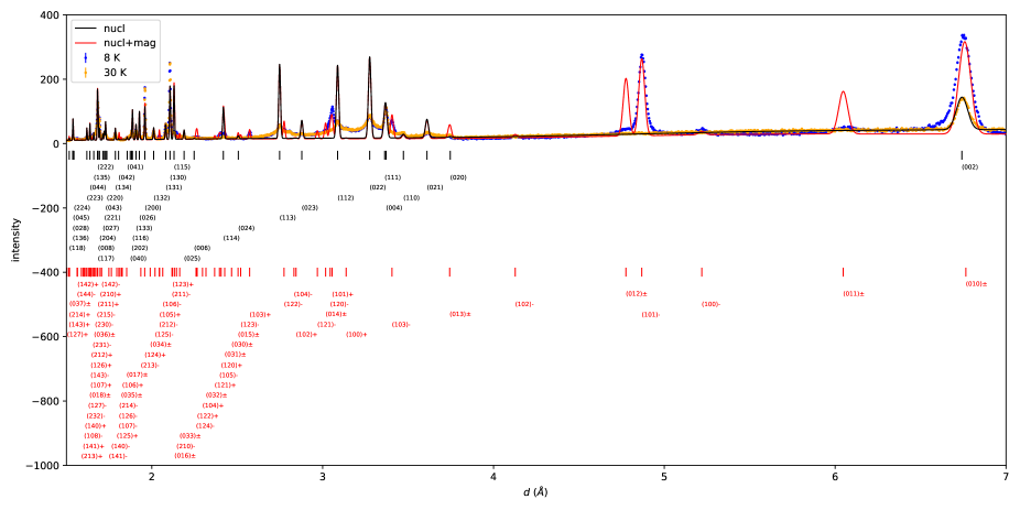
In Fig. S1, we show the 8 and 30 K data, along with calculated intensity for an ideal orthorhombic CrI2 structure, both for purely nuclear neutron scattering and with magnetic scattering included. The nuclear and magnetic peak locations are depicted underneath.
VI.2 Computation of the diffuse scattering
Here, we discuss our usage of the formalism of Ref. Treacy et al. (1991) to compute the diffuse scattering intensity. Although DIFFaX, the software based on this formalism, cannot do magnetic neutron scattering intensity calculations, it is straightforward to implement the formalism for this purpose.
For nuclear neutron scattering, the layer form factor is defined as
| (2) |
The only difference from the formula for the (nuclear) structure factor is that the sum, here, is only over atoms for a single layer. The nuclear scattering length of the th atom is , is the th atom’s position, is the momentum transfer, and is the Debye-Waller factor (set to Å2 for all atoms.)
In the formalism used here for orthorhombic-like stacking disorder, we consider four types of layers, depending on whether the layers are oriented along the -axis, and depending on whether those layers were preceded by an A- or B-type stacking boundary (which would result in different in-plane translations relative to the layer below.) Thus, we can construct a matrix of the layer form factors for the four types of layers. Next, we construct the matrix . Its elements are , where is the translation from a type- bottom layer to a type- layer above it (including the out-of-plane component ), and is the probability of having a type- upper layer given a type- bottom layer. Next, we solve for the scattered wavefunction amplitude matrix , which requires inverting , where is the identity matrix. To avoid singularities, we follow the advice of Treacy et al. Treacy et al. (1991), who recommend multiplying the elements of by , with chosen to be . This “trick” adds an effective uncertainty to the layer translations, and its effect is to almost imperceptibly broaden peaks while allowing the calculation to converge. Finally, the intensity can be calculated via , where is the matrix with elements , with being the overall frequency of having layers of type . and denote the transpose and complex conjugate of , respectively. Intensity “rods” are computed at positions , with integer and and a grid of points along . Once the intensity rods have been calculated, the intensity is powder-averaged, then convoluted with the instrument resolution function and multiplied by the Lorentz factor for time-of-flight neutron scattering to simulate the data.
For magnetic scattering, a similar method is followed. First, the magnetic structure factor of a peak, given helimagnetic ordering with a modulation vector , is Kuindersma et al. (1981); Carpenter and Loong (2015)
| (3) |
The index runs over every Cr2+ ion in the unit cell. Here, fm, is the magnetic form factor (in this case, for Cr2+), is the location of , is the Fourier component of the th magnetic moment in the unit cell ( are in reference to the “untwisted” spins of the unit cell, before applying the helical rotation), is the position of the th ion, is a phase factor for the th spin, and is the Debye-Waller factor. The unit vectors and are orthogonal, defining the plane of rotation for the spin helix.
The magnetic layer form factor is defined analogously to the case of nuclear scattering, with the same form as Eq. 3 except that the sum runs over spins in only one layer rather than all layers in a unit cell. An important difference from nuclear scattering is that is a vector rather than a scalar Shirane et al. (2002), i.e., it will have components , , and . A magnetic Bragg peak measured with unpolarized neutrons will have an intensity proportional to , where is the magnetic structure factor at a reciprocal lattice vector . In other words, we can determine the intensity from the sum of three contributions corresponding to the , , and axes. We then follow the formalism of Treacy, et al. Treacy et al. (1991), except that we sum three separate contributions, corresponding to the three magnetic layer form factors , , and , each contribution computed analogously as for the nuclear diffuse scattering.
VI.3 Magnetic intensity calculations for different planes of helical rotation
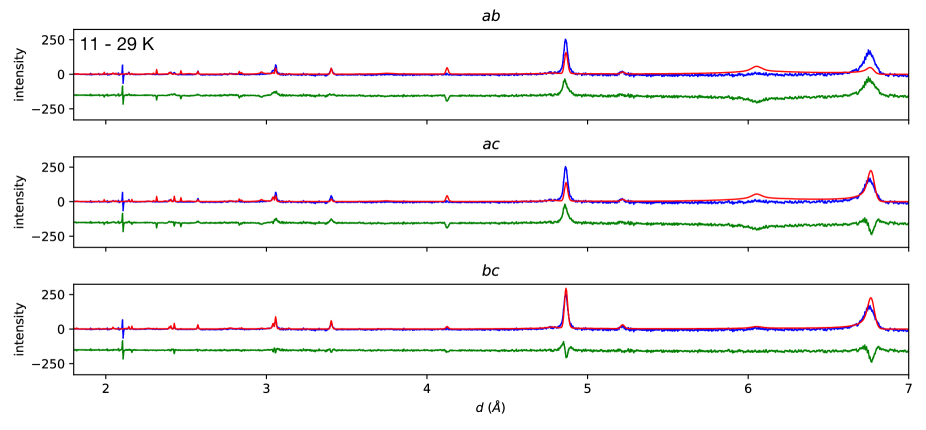
In Fig. S2, we show calculated magnetic intensity using the same parameters as for Fig. 3(b) of the main text, except that only the magnetic intensity is shown (i.e., the 11 K minus 29 K intensity), and that calculations were done for three different planes of helical rotation: the , , and planes. We see that the plane best describes the data. In other words, the helical spin order for orthorhombic CrI2 is most likely screw-like, in contrast to the cycloidal order reported for CuCl2 and CuBr2 Banks et al. (2009); Lee et al. (2012).
VI.4 Additional magnetization data
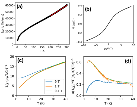
In Fig. S3(a), we show the inverse susceptibility for the same data as in Fig. 5. The red line indicates a Curie-Weiss fit of a line to the region K, from which we obtained K and an effective moment of = 3.89 . (The fitted uncertainties were 0.4 K and 0.0025 , respectively, but the true uncertainties were certainly larger, perhaps due to impurities induced by water absorption; for instance, another Curie-Weiss analysis on a separate crystal (at 9 T, with in-plane field) yielded K and 4.186 .) The ideal effective moment for , would be 4.90 , suggesting a deviation from Curie-Weiss behavior or the effect of impurities in our measurements.
In Fig. S3(b), we show a magnetization-field hysteresis loop at 3 K for the same crystal and () orientation as for Fig. 5. The magnetization is roughly linear in field up to 1 to 2 T, but deviates from linearity for larger fields. At 9 T, the magnetization is still well below the expected saturation value of 4 /Cr for and . In Fig. S3(c,d) we show magnetization data for an additional melt-grown CrI2 crystal, for fields at 0.1, 1, and 9 T. The inverse susceptibility in Fig. S3(c) nearly overlaps between 0.1 and 1 T, both showing similar behavior as for Fig. 5, but the 9 T data show different behavior, suggesting that a field beyond 3 T (judging from Fig. S3(b)) may induce a change in magnetic ordering. Neutron diffraction studies under magnetic field would clarify this behavior.
| (meV) | (meV) | ||
|---|---|---|---|
| 10.88 | 16.88 | ||
| 18.67 | 18.85 | ||
| -1.95 | -3.08 | ||
| 12.36 | 9.59 | ||
| 7.78 | 1.96 | ||
| -6.63 | -10.25 |
VI.5 Selection of crystal structure for calculation
VI.6 Computation of
Six ordered spin arrangement of CrI2 (shown in Fig. S5) were generated to extract the spin-exchange parameter from DFT calculations. The total spin-exchange energies for each ordered spin state for the supercell can be written as: