Magnetic eight-fold nodal-point and nodal-network fermions in MnB2
Abstract
Realizing topological semimetal states with novel emergent fermions in magnetic materials is a focus of current research. Based on first-principles calculations and symmetry analysis, we reveal interesting magnetic emergent fermions in an existing material MnB2. In the temperature range from 157 K to 760 K, MnB2 is a collinear antiferromagnet. We find the coexistence of eight-fold nodal points and nodal network close to the Fermi level, which are protected by the spin group in the absence of spin-orbit coupling. Depending on the Néel vector orientation, consideration of spin-orbit coupling will either open small gaps at these nodal features, or transform them into magnetic linear and quadratic Dirac points and nodal rings. Below 157 K, MnB2 acquires weak ferromagnetism due to spin tilting. We predict that this transition is accompanied by a drastic change in anomalous Hall response, from zero above 157 K to below 157 K.
Topological semimetals have been attracting great interest in condensed matter physics research Chiu et al. (2016); Yan and Felser (2017); Armitage et al. (2018); Lv et al. (2021). In these materials, the symmetry/topology protected band degeneracies in the vicinity of Fermi level give rise to novel emergent fermion states, which may lead to fascinating physical effects. Early examples include Weyl and Dirac semimetals, which host twofold and fourfold nodal points, respectively, and can simulate the physics of Weyl and Dirac fermions Armitage et al. (2018). Subsequent works showed that there is a rich variety of emergent fermions beyond the Weyl and Dirac paradigm, which may have different number of degeneracy and different dimension of the band degeneracy manifold Fang et al. (2012); Yang and Nagaosa (2014); Bradlyn et al. (2016); Wieder et al. (2016); Zhu et al. (2016); Yu et al. (2022). Recent classification works showed that the maximal degree of degeneracy that can be protected by crystalline symmetry is eight Wieder et al. (2016); Bradlyn et al. (2016); Yu et al. (2022); Liu et al. (2022); Zhang et al. (2022); Tang and Wan (2022); Rong et al. (2023). Such eightfold nodal point (ENP) has been proposed in a few nonmagnetic crystals, such as Bi2CuO4 Bradlyn et al. (2016),Bi2AuO5 Wieder et al. (2016), TaCo2Te2 Rong et al. (2023) and etc. In Refs. Rong et al. (2023), ENP in TaCo2Te2 has been probed by angle-resolved photoemission spectroscopy (ARPES). Besides nodal points which are zero-dimensional (0D), the degeneracy manifold may also form 1D nodal lines Yang et al. (2014); Weng et al. (2015); Fang et al. (2016); Zhu et al. (2023) or even 2D nodal surfaces Liang et al. (2016); Zhong et al. (2016); Bzdušek and Sigrist (2017); Wu et al. (2018) . Especially, the nodal lines can be connected to form various patterns in the momentum space Bzdušek et al. (2016); Wang et al. (2017); Yu et al. (2017); Sheng et al. (2017).
A recent focus in the field is to extend the study from nonmagnetic to magnetic systems. This is motivated by several points. First, due to magnetic ordering, symmetries of magnetic systems that underly topological semimetal states are different and are much richer compared to nonmagnetic systems. Second, magnetism offers a new possibility to control band topology and topological phase transitions, e.g., by tuning the magnetic moment orientation. Finally, magnetic materials are technologically important. Topological features and emergent fermions may endow them with new advantages for applications. Currently, the realization of unconventional fermions in magnetic materials is still rather limited. In Ref. Schoop et al. (2018), a ENP was reported in antiferromagnetic CeSbTe, but its energy is quite far away from Fermi level. Thus, it remains an important task to search for suitable magnetic materials that can host ENPs and other interesting topological states.
In this work, based on first-principles calculations and symmetry analysis, we reveal that the existing intermetallic compound MnB2 is actually a magnetic topological semimetal with rich emergent fermion states. MnB2 itself has two notable features Legrand and Neov (1972). First, it has a high Néel temperature of 760 K. Second, it exhibits more than one magnetic phases. Between 157 K and 760 K, it adopts collinear antiferromagnetic (AFM) ordering. Below 157 K, it transitions into a phase exhibiting weak ferromagnetism (wFM), due to small tilting of the local moments. We find that in the collinear AFM phase, MnB2 possesses a pair of ENPs and an interesting nodal network formed by three sets of nodal loops in its low-energy band structure, protected by the spin group in the absence of spin-orbit coupling (SOC). Depending on the Néel vector orientation, SOC will either open small gaps at these degeneracies or transform them into fourfold linear and quadratic Dirac points and separated nodal rings. Effective models are constructed for these nodal features. In addition, we find that due to symmetry constraint, there will a drastic change in the anomalous Hall response accompanying the transition at 157 K: Anomalous Hall response is forbidden by symmetry in the collinear AFM phase, whereas it can become sizable in the wFM phase. We estimate that the intrinsic anomalous Hall conductivity can reach up to below 157 K. Our work identifies a promising platform to study novel emergent fermions and their interplay with magnetic ordering.
I Computation Method
Our first-principles calculations were based on the density functional theory (DFT), using a plane-wave basis set and projector augmented wave method Blöchl (1994), as implemented in the Vienna ab initio simulation package Kresse and Furthmüller (1996); Kresse and Joubert (1999). The generalized gradient approximation (GGA) parameterized by Perdew, Burke, and Ernzerhof (PBE) was adopted for the exchange-correlation functional Perdew et al. (1996). The energy cutoff was set to 390 eV. A Monkhorst-Pack mesh was used for the Brillouin zone (BZ) sampling. The atomic positions were fully optimized until the residual forces were less than eV/Å. The convergence criterion for the total energy was set to be eV. To account for the correlation effects of the Mn-3d electrons, we have adopted the GGA method Dudarev et al. (1998). We have tested different values, and found that eV gives a calculated magnetic moment , which best matches previous experimental observation () Legrand and Neov (1972), therefore, this value was taken for the results presented below. The effective models were constructed with the help of the MagneticKP package Zhang et al. (2023). The intrinsic anomalous Hall conductivity was evaluated on a denser k mesh of by using the WANNIER90 package Wang et al. (2006); Mostofi et al. (2008).
II Crystal structure and magnetism
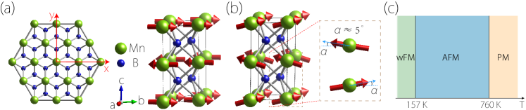
The intermetallic compound MnB2 has been synthesized in experiment more than sixty years ago Binder and Post (1960). The crystal has the hexagonal AlB2 type structure with space group (No. 191). As depicted in Fig. 1, it consists of alternating atomic layers of Mn and B along the axis ( direction in our setup). Mn layers are of simple hexagonal type, whereas B layers are of honeycomb type. A primitive unit cell contains one formula unit. The Mn atom occupies the 1a Wyckoff position, whereas the B atoms are at the 2d position. The experimental lattice constants are Å and Å Cadeville (1966), which have been adopted in our first-principles calculations.
The magnetic structures of MnB2 have been studied in previous experiments Legrand and Neov (1972). From magnetic measurements, such as nuclear magnetic resonance and neutron diffraction, it was found that MnB2 has two magnetic phases. The magnetic moments are mainly on the Mn sites and have a value . At room temperature, MnB2 has A-type collinear AFM, where each Mn atom layer is FM ordered and neighboring layers are coupled in AFM manner, as illustrated in Fig. 1(a). Measurement showed that the Néel vector perfers to be in the plane. It was found that this collinear AFM phase occupies a wide temperature range from 157 K to 760 K. Below 157 K, MnB2 enters the wFM phase, where the magnetic moments slightly tilt out of the plane, with a tilt angle , as illustrated in Fig. 1(b), which leads to a network magnetization along . These experimental results will be used in our modeling below.
| Configuration | AFM- | AFM- | AFM- | FM- | |
| Total Energy | 0.00 | 0.27 | 0.40 | 0.85 |
III Nonrelativistic band structure of AFM phase
Let’s investigate the electronic properties of MnB2 in the collinear AFM phase [as in Fig. 1(a)]. We first consider the nonrelativistic band structure, i.e., in the absence of SOC. The result obtained from our DFT calculation is plotted in Fig. 2(a). One observes that the system is metallic, which agrees with the transport measurement result reported in Ref. Kasaya and Hihara (1970) The density of states (DOS) shows a dip at the Fermi level, reflecting its semimetal character. From projected DOS (PDOS), the low-energy bands are mainly contributed by Mn-3d and B-2p orbitals.
Interestingly, one observes several linear band crossings in the vicinity of Fermi level. First of all, there is a crossing point on the - path, located at (in unit of , is the lattice constant for the magnetic cell) and at energy of eV below Fermi level, as indicated by the red arrow in Fig. 2(a) (There is also a partner point at due to inversion symmetry). Note that due to AFM ordering, spin degree of freedom has to be considered, and each band in the band structure is at least doubly degenerate with the spin degeneracy. Then, one can see from Fig. 2(a) that the two bands which cross at are each fourfold degenerate, hence point is an ENP.
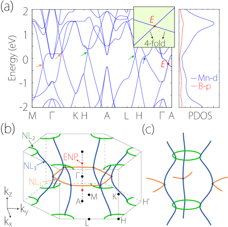
Meanwhile, there are other crossing points marked by arrows with different colors in Fig. 2(a), a careful scan of BZ shows that these points actually belong to several nodal loops. As illustrated in Fig. 2(b), there is a nodal ring centered at point in the plane (orange colored in Fig. 2(b)), marked as NL1. Two (green colored) nodal rings are centered at and points in the plane, marked as NL2. In addition, there are six (blue colored) loops traversing BZ in the direction, marked as NL3. These nodal loops are fourfold degenerate and they are connected to form an interesting network pattern as shown in Fig. 2(c) in the extended BZ.
All these nodal features in the nonrelativistic band structure are protected by spin group symmetry Litvin and Opechowski (1974). Let’s first consider the protection of the nodal loops. Without SOC, the spin-up and spin-down channels can be considered separately (and the two are connected, e.g., by translation of along , which enforces the band spin degeneracy). If we focus on one spin channel, it can be regarded as a spinless system, which has an effective time reversal symmetry (represented by the complex conjugation). In addition, the inversion (with inversion center on Mn site), horizontal mirror (coincides with Mn plane), and three vertical mirrors are respected in each spin channel. These symmetries are sufficient to protect the nodal loops in Fig. 2(b). For example, the loops in the and planes are protected by the symmetry, i.e., in each spin channel, the two crossing bands have opposite eigenvalues. Similarly, the six blue colored nodal loops are protected by the three vertical mirrors. Furthermore, one notes that each spin channel respects the spinless symmetry, which enforces quantization of Berry phases in unit of . This offers a second protection of the loops, as any small closed path encircling a loop here must carry a Berry phase. It follows that even if the mirrors are weakly broken, these loops will not disappear as along as the inversion symmetry is still preserved.
Now we turn to ENP (point ) and analyze its protection. In this analysis, we shall also construct an effective model for its description. For spin groups, the actions on spatial and spin spaces are independent and can be separated. We first consider the symmetries acting only on spatial (orbital) degrees of freedom. The ENP is formed by the crossing by two degenerate bands on - path. For orbital degrees of freedom, there are two symmetry generators on this path, namely the sixfold rotation and the vertical mirror . The corresponding little co-group has two (single valued) two-dimensional (2d) irreducible representations (IRRs) and on this path. The matrix representations for the generators in and may be taken as
| (1) |
and
| (2) |
Each 2D IRR gives a doubly degenerate band, and the accidental crossing between them will lead to a fourfold degenerate point on -.
Next, we take into account the spin degree of freedom, which will double the degeneracy. This introduces additional generators for the spin group. These include, e.g., all possible rotations of spin along its polarization direction. Assuming the moments are in the direction (the specific direction does not matter here since there is no SOC), then such rotations, sometimes denoted as Litvin and Opechowski (1974), can be represented as , where is any real number and is the Pauli matrix. In addition, reversing the spin direction (e.g., by rotation normal to the spin polarization direction or by time reversal 111Here, we use script font to distinguish it from the effective discussed above that does not acting on spin.) and interchange the two AFM sublattices (e.g., by or by translation of along ) is also an allowed symmetry. Including spin, gives rise to spin group IRR which is four dimensional, for which the generators can be taken as
| (3) |
where is the identity matrix, and is the translation of along the direction (i.e., half of the magnetic cell length along ).
Using these matrix representations, we can construct the model for the ENP. Up to linear order in (i.e. the momentum deviation from point ), the model is given by
| (4) |
Here, the model is an matrix with , ’s are real model parameters, and the energy is measured from the ENP.
Before proceeding, we comment that besides the nonmagnetic versus magnetic difference, all previously reported ENPs in fact require protection by nonsymmorphic space group symmetries and they all locate at high-symmetry points at the boundary of BZ Wieder et al. (2016); Bradlyn et al. (2016); Rong et al. (2023). In contrast, the ENP here is stabilized only by symmorphic symmetries and it occurs on a high-symmetry path in the interior of BZ. It also follows that the ENP here comes in a pair, whereas previous cases all have a single point.
IV Effect of Spin-orbit coupling
In this section, we examine the effect of SOC in the collinear AFM phase. With SOC, the orientation of Néel vector will affect band structure. Note that the previous experiments only showed the Néel vector prefers to be in-plane, but they did not determine the specific in-plane direction Legrand and Neov (1972). Our DFT calculation suggests that the energy of direction is slightly lower than the direction (see Table I). (The qualitative features of results for the two in-plane directions are essentially the same.)
Let’s first consider the case with Néel vector along the direction, denoted as AFM- configuration. With SOC, symmetry operations will act on orbital and spin spaces simultaneously. Note that the system still respects symmetry, where the inversion center is in the B layer at the center of a B hexagon. As a result, each band still has a twofold spin degeneracy due to . Furthermore, we find that SOC generally opens a small gap at all the nodal features near Fermi level. Figure 3(a) and 3(b) show the enlarged band structures around two original band crossings on high-symmetry paths. The opened SOC gap ranges from a few meV to meV.

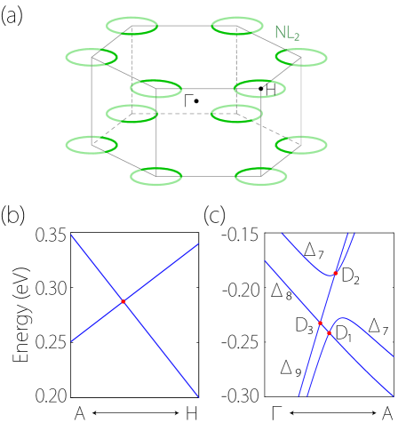
Next, we consider the configuration with Néel vector along the direction, denoted as AFM-. In this case, we find that there are still preserved nodal features near Fermi level. First of all, regarding the nodal network in Fig. 2(b), we find that the two nodal rings in the plane (the NL2 rings) are preserved, while other nodal lines open small gaps, as illustrated in Fig. 4(a). The symmetry protection of these fourfold nodal rings come from the combined actions of the horizontal mirror and symmetries. Here, each nodal ring is formed by the crossing of two doubly degenerate bands, where the double degeneracy comes from . To have a protecting crossing, it is essential that the related partners must have the same eigenvalues. To demonstrate this point, consider a band eigenstate with momentum in the plane. It can always be chosen as an eigenstate, i.e.,
| (5) |
where or in the presence of SOC. To find the eigenvalue of its partner , we need to know the relationship between operations and . Considering their consecutive actions on a spatial point , we have
| (6) |
and
| (7) |
Therefore, we have
| (8) |
where in the second step, we have used and is purely imaginary. This demonstrates that the partners and must have the same eigenvalue . When bands with opposite values cross, they will form the fourfold band crossing (see Fig. 4(a)), i.e., the NL2 rings. One also notes from Eq. (8) that the condition is important; the other mirror plane does not have this property. This explains why the original nodal ring NL1 in Fig. 2(a) is not preserved.
Next, we consider the SOC effect on the ENP in the AFM- state. We find that each ENP will be transformed into three fourfold Dirac points on - path. These points are marked in the calculated band structure in Fig. 4(c). Two points are conventional linear Dirac points (marked as and in the figure). Interesting, the third one is a quadratic Dirac point Zhu et al. (2018); Wu et al. (2020) (marked as ), which has linear band splitting along but quadratic band splitting in the 2D plane normal to .
To characterize these Dirac points, we construct their effective models. The magnetic space group for AFM-z is (BNS No. 192.252). The low-energy bands that form the Dirac points belong to , , and irreducible representations on the - path, as shown in Fig. 4(c). The symmetry generators on this path can be selected as , , and , where is a glide mirror involving a half magnetic cell translation along . Their matrix representations for , , and can be taken as
| (9) |
and
| (10) |
| (11) |
for . For the linear Dirac point formed by the crossing of and bands, the obtained effective model takes the form of
| (12) |
where . Similar, point formed by the crossing of and is described by the model of
| (13) |
Lastly, the quadratic Dirac point is formed by the crossing of and . Its model is given by
| (14) | ||||
In the above models, the energy and the momentum are measured from each nodal point, and ’s, ’s, and ’s are real model parameters. These models confirm that and are linear Dirac points, and is a quadratic Dirac point, all realized in an AFM state. It should be noted that although quadratic Dirac point was proposed before based on theoretical analysis in nonmagnetic and magnetic systems Zhu et al. (2018); Wu et al. (2020). Its material realization is rare. Particularly, to our knowledge, it has not been reported in magnetic materials before.
V Anomalous Hall response in FM phase
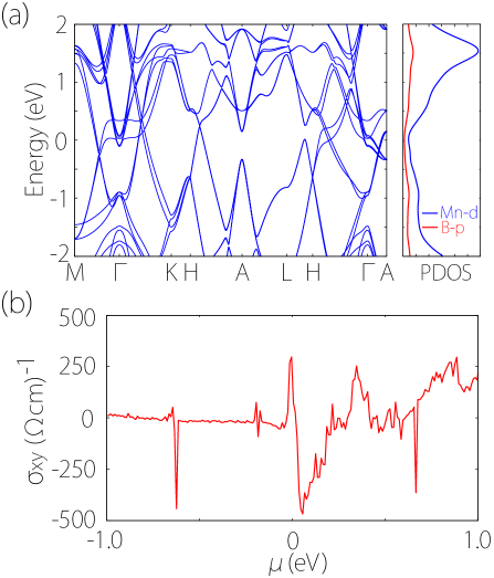
Experiment shows that when the temperature is below 157 K, MnB2 will transition into the wFM phase, with magnetic moments tilted toward the c axis by a small angle () Legrand and Neov (1972), as shown in Fig. 1(b). The magnetic space group changes into (BNS No. 63.462), in which the symmetries and are respected. The calculated band structure of the wFM phase in shown in Fig. 5(a). One observes that, first, the twofold band degeneracy in the AFM phase is lifted in the wFM phase. Second, the system is still metallic, and low-energy bands show complicated crossing patterns.
Here, we are interested in the anomalous Hall response. The reason is that in the AFM phase, regardless of the Néel vector orientation, this response is forbidden in bulk MnB2, by the symmetry, where is the translation along by half of the AFM cell. Now, in the wFM phase, this symmetry is broken by the moment tilting, so the system can exhibit a finite anomalous Hall response. This can serve as a contrasting property between the two phases.
We evaluate the intrinsic part of anomalous Hall conductivity in the plane, which is related to the Berry curvature of the material’s band structure Jungwirth et al. (2002); Nagaosa et al. (2010):
| (15) |
Here, is the total Berry curvature of all occupied states at
| (16) |
where and are band indices, is the band energy, ’s are the velocity operators, and is the Fermi distribution function for state .
Figure 5(b) shows the obtained from our DFT calculations as a function of the chemical potential . We find that without doping (), has a value of , which is actually sizable, considering that good FM materials such as Fe has a value around Yao et al. (2004). Moreover, with small electron doping, can have a large change and even flip its sign, reaching at meV (i.e., doping of e/f.u.). These results show that the anomalous Hall signal will exhibit a large jump during the magnetic phase transition, from nearly zero in the AFM phase to a sizable value in the wFM phase.
VI Discussion and Conclusion
We have revealed interesting band nodal features in MnB2. The ENPs found here is distinct from previously reported cases, which are either in nonmagnetic systems or require nonsymmorphic symmetries Wieder et al. (2016); Bradlyn et al. (2016); Rong et al. (2023). As we discussed, the ENPs here are realized in AFM state and requires only symmorphic spin group symmetries. It follows that they appear in a pair, rather than a single point in previous examples. The AFM quadratic Dirac point is another interesting discovery. It should be noted that all Dirac points here have zero Chern numbers, because the system has both and symmetries.
Experimentally, single crystal MnB2 has already been synthesized Binder and Post (1960). The nodal features predicted here can be imaged by the angle-resolved photoemission spectroscopy (ARPES) technique. Note that the AFM phase exists between 157 K and 760 K. In this range, the SOC induced splitting in low-energy bands are comparable or even less than the temperature broadening. Hence, the small SOC gap may not be resolved in ARPES images, so nodal features like ENP and nodal network can be well perceived. Finally, the anomalous Hall response can be studied with the standard Hall bar configuration.
In conclusion, we discover topological semimetal states in an existing magnetic material MnB2. In the AFM phase above 157 K, we reveal a pair of ENPs coexisting with a nodal network. The ENPs are protected by symmorphic spin group symmetries and located on a high-symmetry path, distinct from previous cases. The nodal network is composed of three types of nodal loops, and each loop enjoys a double symmetry protection. SOC may open a small gap at these degeneracies. In the AFM-z state, a pair of nodal rings are robust against SOC, and the ENP splits into three Dirac points, one of which is a magnetic quadratic Dirac point. For the wFM phase below 157 K, we predict a sizable anomalous Hall response , which contrasts to the AFM phase with the response forbidden by symmetry. Our work reveals a concrete material platform for studying magnetic topological semimetal states with unconventional emergent fermions. The jump in anomalous Hall signal could be used to probe the magnetic transition and may be useful for designing new spintronic devices.
Acknowledgements.
The authors thank D. L. Deng for valuable discussions. This work is supported by the Project of Educational Commission of Hunan Province of China (Grant No. 21A0066), the Hunan Provincial Natural Science Foundation of China (Grant No. 2022JJ30370), the National Natural Science Foundation of China (Grants No. 11704117), the UGC/RGC of Hong Kong SAR (AoE/P-701/20) and Singapore NRF CRP (CRP22-2019-0061). We acknowledge computational support from H2 clusters in Xi’an Jiaotong University and National Supercomputing Centre Singapore.References
- Chiu et al. (2016) C.-K. Chiu, J. C. Y. Teo, A. P. Schnyder, and S. Ryu, Rev. Mod. Phys. 88, 035005 (2016).
- Yan and Felser (2017) B. Yan and C. Felser, Annu. Rev. Condens. Matter Phys. 8, 337 (2017).
- Armitage et al. (2018) N. P. Armitage, E. J. Mele, and A. Vishwanath, Rev. Mod. Phys. 90, 015001 (2018).
- Lv et al. (2021) B. Q. Lv, T. Qian, and H. Ding, Rev. Mod. Phys. 93, 025002 (2021).
- Fang et al. (2012) C. Fang, M. J. Gilbert, X. Dai, and B. A. Bernevig, Phys. Rev. Lett. 108, 266802 (2012).
- Yang and Nagaosa (2014) B.-J. Yang and N. Nagaosa, Nat. Commun. 5, 4898 (2014).
- Bradlyn et al. (2016) B. Bradlyn, J. Cano, Z. Wang, M. G. Vergniory, C. Felser, R. J. Cava, and B. A. Bernevig, Science 353, aaf5037 (2016).
- Wieder et al. (2016) B. J. Wieder, Y. Kim, A. M. Rappe, and C. L. Kane, Phys. Rev. Lett. 116, 186402 (2016).
- Zhu et al. (2016) Z. Zhu, G. W. Winkler, Q. Wu, J. Li, and A. A. Soluyanov, Phys. Rev. X 6, 031003 (2016).
- Yu et al. (2022) Z.-M. Yu, Z. Zhang, G.-B. Liu, W. Wu, X.-P. Li, R.-W. Zhang, S. A. Yang, and Y. Yao, Sci. Bull. 67, 375 (2022).
- Liu et al. (2022) G.-B. Liu, Z. Zhang, Z.-M. Yu, S. A. Yang, and Y. Yao, Phys. Rev. B 105, 085117 (2022).
- Zhang et al. (2022) Z. Zhang, G.-B. Liu, Z.-M. Yu, S. A. Yang, and Y. Yao, Phys. Rev. B 105, 104426 (2022).
- Tang and Wan (2022) F. Tang and X. Wan, Phys. Rev. B 105, 155156 (2022).
- Rong et al. (2023) H. Rong, Z. Huang, X. Zhang, S. Kumar, F. Zhang, C. Zhang, Y. Wang, Z. Hao, Y. Cai, L. Wang, et al., npj Quantum Mater. 8, 29 (2023).
- Yang et al. (2014) S. A. Yang, H. Pan, and F. Zhang, Phys. Rev. Lett. 113, 046401 (2014).
- Weng et al. (2015) H. Weng, Y. Liang, Q. Xu, R. Yu, Z. Fang, X. Dai, and Y. Kawazoe, Phys. Rev. B 92, 045108 (2015).
- Fang et al. (2016) C. Fang, H. Weng, X. Dai, and Z. Fang, Chin. Phys. B 25, 117106 (2016).
- Zhu et al. (2023) Z. Zhu, H. Liu, Y. Ge, Z. Zhang, W. Wu, C. Xiao, and S. A. Yang, Phys. Rev. B 107, 205120 (2023).
- Liang et al. (2016) Q. F. Liang, J. Zhou, R. Yu, Z. Wang, and H. Weng, Phys. Rev. B 93, 085427 (2016).
- Zhong et al. (2016) C. Zhong, Y. Chen, Y. Xie, S. A. Yang, M. L. Cohen, and S. Zhang, Nanoscale 8, 7232 (2016).
- Bzdušek and Sigrist (2017) T. Bzdušek and M. Sigrist, Phys. Rev. B 96, 155105 (2017).
- Wu et al. (2018) W. K. Wu, Y. Liu, S. Li, C. Y. Zhong, Z. M. Yu, X. L. Sheng, Y. X. Zhao, and S. A. Yang, Phys. Rev. B 97, 115125 (2018).
- Bzdušek et al. (2016) T. Bzdušek, Q. Wu, A. Rüegg, M. Sigrist, and A. A. Soluyanov, Nature 538, 75 (2016).
- Wang et al. (2017) S.-S. Wang, Y. Liu, Z.-M. Yu, X.-L. Sheng, and S. A. Yang, Nat. Commun. 8, 1844 (2017).
- Yu et al. (2017) R. Yu, Q. Wu, Z. Fang, and H. Weng, Phys. Rev. Lett. 119, 036401 (2017).
- Sheng et al. (2017) X.-L. Sheng, Z.-M. Yu, R. Yu, H. Weng, and S. A. Yang, J. Phys. Chem. Lett. 8, 3506 (2017).
- Schoop et al. (2018) L. M. Schoop, A. Topp, J. Lippmann, F. Orlandi, L. Müchler, M. G. Vergniory, Y. Sun, A. W. Rost, V. Duppel, M. Krivenkov, et al., Sci. Adv. 4, eaar2317 (2018).
- Legrand and Neov (1972) E. Legrand and S. Neov, Solid State Commun. 10, 883 (1972).
- Blöchl (1994) P. E. Blöchl, Phys. Rev. B 50, 17953 (1994).
- Kresse and Furthmüller (1996) G. Kresse and J. Furthmüller, Phys. Rev. B 54, 11169 (1996).
- Kresse and Joubert (1999) G. Kresse and D. Joubert, Phys. Rev. B 59, 1758 (1999).
- Perdew et al. (1996) J. P. Perdew, K. Burke, and M. Ernzerhof, Phys. Rev. Lett. 77, 3865 (1996).
- Dudarev et al. (1998) S. L. Dudarev, G. A. Botton, S. Y. Savrasov, C. J. Humphreys, and A. P. Sutton, Phys. Rev. B 57, 1505 (1998).
- Zhang et al. (2023) Z. Zhang, Z.-M. Yu, G.-B. Liu, Z. Li, S. A. Yang, and Y. Yao, Comput. Phys. Commun. 290, 108784 (2023).
- Wang et al. (2006) X. Wang, J. R. Yates, I. Souza, and D. Vanderbilt, Phys. Rev. B 74, 195118 (2006).
- Mostofi et al. (2008) A. A. Mostofi, J. R. Yates, Y.-S. Lee, I. Souza, D. Vanderbilt, and N. Marzari, Comput. Phys. Commun. 178, 685 (2008).
- Binder and Post (1960) I. Binder and B. Post, Acta Crystallogr. 13, 356 (1960).
- Cadeville (1966) M. Cadeville, J. Phys. Chem. Solids 27, 667 (1966).
- Kasaya and Hihara (1970) M. Kasaya and T. Hihara, J. Phys. Soc. Japan 29, 336 (1970).
- Litvin and Opechowski (1974) D. B. Litvin and W. Opechowski, Physica 76, 538 (1974).
- Note (1) Here, we use script font to distinguish it from the effective discussed above that does not acting on spin.
- Zhu et al. (2018) Z. Zhu, Y. Liu, Z.-M. Yu, S.-S. Wang, Y. X. Zhao, Y. Feng, X.-L. Sheng, and S. A. Yang, Phys. Rev. B 98, 125104 (2018).
- Wu et al. (2020) W. Wu, Z.-M. Yu, X. Zhou, Y. X. Zhao, and S. A. Yang, Phys. Rev. B 101, 205134 (2020).
- Jungwirth et al. (2002) T. Jungwirth, Q. Niu, and A. H. MacDonald, Phys. Rev. Lett. 88, 207208 (2002).
- Nagaosa et al. (2010) N. Nagaosa, J. Sinova, S. Onoda, A. H. MacDonald, and N. P. Ong, Rev. Mod. Phys. 82, 1539 (2010).
- Yao et al. (2004) Y. Yao, L. Kleinman, A. H. MacDonald, J. Sinova, T. Jungwirth, D.-s. Wang, E. Wang, and Q. Niu, Phys. Rev. Lett. 92, 037204 (2004).