Broadband guidance of ultraviolet light in a hollow-core optical fibre
Abstract
We report an anti-resonant hollow core fibre with broadband ultraviolet guidance from 190 – 400 nm, except for a narrow high loss resonance band at 245 – 265 nm. The minimum attenuation is 0.13 dB/m at 235 nm and 0.16 dB/m at 325 nm. With an inscribed core diameter of 12 µm, the fibre’s bend loss was 0.22 dB per turn for a bend radius of 3 cm
1 Introduction
The flexible and robust transmission of ultraviolet (UV) light through optical fibres would be invaluable in reimagining a multitude of applications including ultrafast spectroscopy, precision laser machining and UV generation [1, 2]. However, fibres with solid silica cores suffer increasing attenuation towards shorter wavelengths due to electronic absorptions and Rayleigh scattering. Furthermore, light-induced damage to the silica structure by energetic UV photons causes solarization [3], which is particularly limiting for fibre applications in the far UV. Even specially designed solarization resistant fibres suffer from severe transmission degradation in use, experiencing 6 dB of induced loss after 10 minutes of exposure to 35 mW of incident power at 266 nm [3].
Anti-resonant hollow core fibres (AR-HCFs) can circumvent these problems because the overlap of light with the glass is very small, with air having a low attenuation for much of the UV range. Only towards 200 nm do electronic absorptions by oxygen and water vapour [4, 5] rapidly increase the UV losses, setting the lower limit in air to 190 nm. The reduced overlap, and so absorption loss, has therefore extended the working range of silica-based fibres from the vacuum UV [6] to the mid-IR [7], until material absorption is so great that even the much-reduced overlap of the light with glass causes significant attenuation. While this limit has been thoroughly investigated in the mid-IR [7], the far UV remains largely unexplored due to challenges in fabricating sufficiently thin and small microstructures.
In a simple AR-HCF, Fig. 1, the thin walls of the silica capillaries surrounding the air core act as Fabry-Perot resonators, resulting in leaky confinement of light within "anti-resonant" wavelength ranges. High-loss resonance wavelengths are defined by [7]
| (1) |
where resonance order m is an integer, t is the wall thickness and n is the refractive index of silica. The broad low-loss anti-resonant bands lie in between. Higher order anti-resonant bands have reduced bandwidth and increased overlap of light and glass [8], so the widest bandwidth occurs in the fundamental band (around m = 0.5).
While wall thickness is thus constrained, core size can be varied more widely. Larger cores reduce confinement loss (in the straight fibre) but increase bend loss. For real-world applications a balance can be found when the core diameter is 20 - 30 times the wavelength [9].
These parameters are difficult to achieve for the UV as fibres microstructures must be drawn smaller than those guiding in the visible or infrared. This greater draw-down ratio leads to increased deformation [10] due to surface tension as the fibre is drawn. While fibres with 132 nm [3] and 110 nm [11] core wall thickness have been reported, the fabrication challenge is shown by their low yield and imperfect structure respectively.
One solution to high draw-down ratios is to separate the drawing process into several smaller steps or stages. In a typical stack-and-draw method [7], there is a single intermediate preform stage between the stack and the fibre. Recent work has demonstrated the benefits of two intermediate stages [10, 12], reducing the draw-down ratio at the final fibre stage and yielding greater control of the microstructure. The penalty is a smaller yield, since the final preform contains less glass. The extreme case of this is fibre tapering, which can create the desired structure through effectively many intermediate stages [13, 14]. While suitable for some applications [6], the yield is limited to only tens of centimetres at most.
An alternative approach is to increase the wall thickness (to use a higher-order anti-resonance band) and core size to reduce the required draw-down ratio. This has the effect of reducing the available bandwidth in the UV and increasing bend loss, limiting the range of applications. Recent examples of UV guiding fibres [15, 16, 17] had wall thicknesses of 600 nm and core sizes of 15 – 27 µm, with no measured guidance below 250 nm. The 27 µm core reported in [17] displayed rapidly increasing bend loss for radii below 7 cm.
Here we report an anti-resonant hollow-core fibre with broadband and effectively single-mode guidance from 190 – 400 nm except for a narrow resonance at 245 – 265 nm. The attenuation is 0.13 dB/m at 235 nm and 0.16 dB/m at 325 nm. Bend loss measurements show 95% of straight-fibre transmission at 325 nm for a single turn at a 3 cm bend radius. The fibre was fabricated using a single intermediate preform stage, yielding a continuous length of 250 m; in principle, the 1 m preform contained enough glass to draw 5 km of fibre.
2 Fabrication
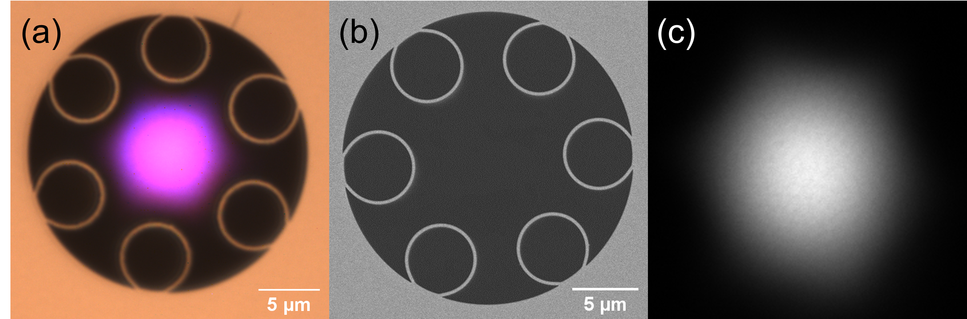
The fibre was fabricated using the stack-and-draw method with a single intermediate stage. All elements were made from Heraeus F300 low-OH synthetic silica. (Although this contains a high proportion of chlorine, we did not observe the presence of ammonium chloride detailed in [18] at any stage.) Preforms in a jacket tube were drawn to 140 µm diameter fibre, under a tension of 430 ± 15 g, typical for our fibre draws for targeting this spectral range. Parameter sweeps to explore different drawing parameters were performed in lengths of 100 - 1000 m, then 250 m of the reported fibre was collected in a single length. Fig. 1(a) is an optical micrograph, while Fig.1(b) is a scanning electron micrograph (SEM) of the fibre cross section.
3 Broadband UV guidance
For all measurements an Energetiq EQ-99X laser-driven light source was used, with offset parabolic mirrors to couple the light into the fibre. Spectra were measured using a Bentham DTMc300 double monochromator and large-area UV photodetector. Near-field images were taken using a silicon camera; they appeared to show the fundamental mode with no apparent change on bending the fibre, Fig. 1(c), suggesting effectively single-mode guidance.
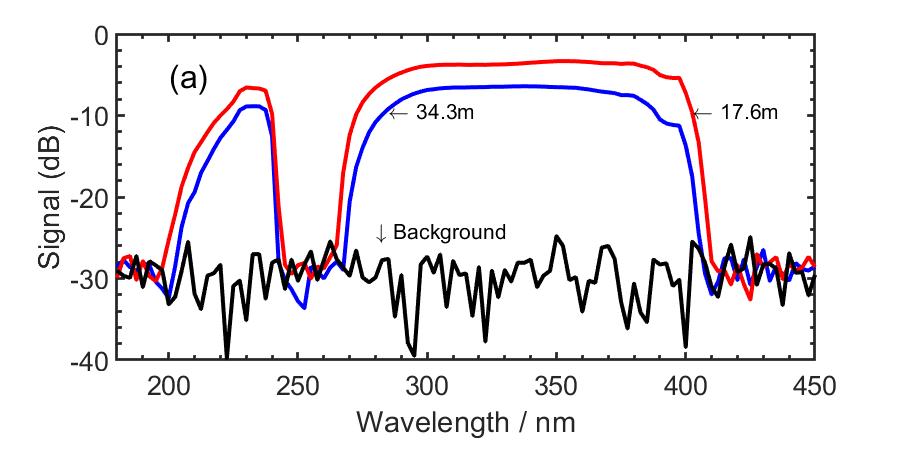
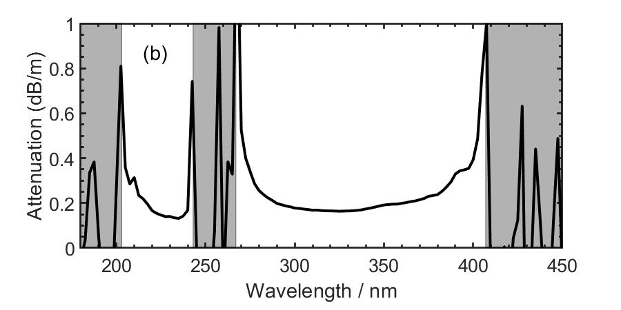
The fibre attenuation was measured using a cutback experiment. 34.3 m of fibre was wound in loose loops of 45 cm diameter on a table to minimise bend loss. Transmission spectra through the fibre, recorded before and after cutting the fibre back to 17.4 m, are shown in Fig. 2 along with the attenuation. The spectra show broadband low-loss guidance from 190 - 400 nm, except for a high loss resonance band at 245 - 265 nm. The minimum attenuation was 0.13 dB/m at 235 nm and 0.16 dB/m at 325 nm. Similar reported fibres had attenuations of 0.08 dB/m at 214nm [3] and 0.050, 0.0097 dB/m at 290, 369 nm [15]. The pattern of bands indicates that 255 nm is the m = 2 resonance. Eq. 1 then gives a wall thickness of 225 nm.
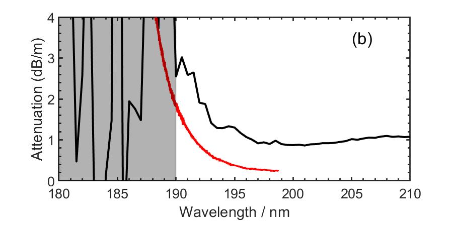
A shorter cutback from 2.2 m to 1.2 m was performed to examine wavelengths below 200 nm, where loss is higher, Fig. 3. Light is guided at wavelengths down to 190 nm, beyond which absorption by oxygen and water vapour [5, 4] prevents measurements in air. The higher attenuations compared to Fig. 2 are consistent with the persistence of higher-order modes in the short fibre, along with absorption by water vapour (plotted with the measured attenuation in Fig. 3 for room conditions close to our experiment). Based on the wall thickness inferred above and including material dispersion, Eq.1 indicates the next high loss resonance should be centered on 185 nm.
![[Uncaptioned image]](/html/2310.07639/assets/shortcutback1.jpg)
4 Bend Loss
Many applications require the delivery of light through tight bends with low loss. Using the rough guide that the core should be 20 – 30 times the guided wavelength, the range 600 – 400 nm would be ideally guided by this fibre with its 12 µm core, with increasing bend loss expected at shorter wavelengths.
The spectral transmission through 4 m of loosely wound fibre in 45 cm diameter loops was measured before and after some was wound through 5 turns around a smaller disc. To check that input coupling had not changed, the fibre was returned to the original loose configuration and a final spectrum recorded. Good agreement between the first and last scans indicated the calculated loss was due to the difference in bend conditions only. Bend loss is plotted in Fig. 4 for radii from 3 – 7 cm.
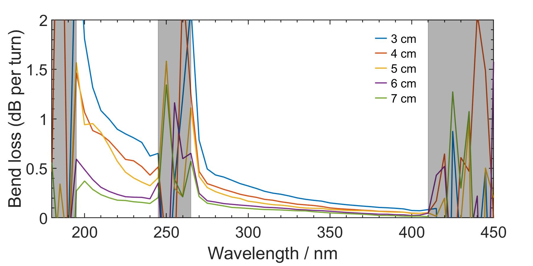
As expected, the shorter wavelengths exhibit higher bend loss than the longer wavelengths. Compared to another recent UV guiding fibre [17], this fibre displays improved bend resistance, with 85% and 95% transmission at 235 and 325 nm for a full turn of 3 cm radius.
5 Discussion
The fabrication challenges associated with UV guiding fibres usually require that the UV bandwidth is sacrificed by using higher-order bands and/or a larger core than optimal for bend loss. These compromises reduce the overall utility of the fabricated fibres and limit their applications. In this work we have shown that the fibre fabrication process can be controlled sufficiently for these compromises to be unnecessary, yielding long lengths of fibre guiding with low loss across most of the UV spectrum down to the edge of the vacuum UV while limiting bend loss. With elimination of water vapour in the fibre core we expect transmission to extend into the VUV via higher order bands. This was achieved using a single intermediate preform stage permitting higher potential yields than the more-complicated two-stage process reported recently [12].
With broadband guidance across nearly the entire UV range in air of 190 – 400 nm, this fibre represents a breakthrough in UV light delivery. Commonly frequency-converted laser wavelengths such as 355, 343, 214 and 206 nm all lie within the guidance windows of this fibre, enabling laser machining, ultrafast and Raman spectroscopy [1, 2, 19] with a variety of sources while avoiding structural damage [20] or solarisation [3]. The guidance of 190 - 200 nm light in a non-tapered fibre for the first time further expands the range of AR-HCFs, with VUV guidance expected in higher order bands in the absence of oxygen or water vapour.
Further work within evacuated or purged fibres will be needed to ascertain the fundamental limits of AR-HCFs in the vacuum UV. In addition, we expect improvements to the fibre structure through the optimization of resonator size to further reduce the attenuation.
6 Backmatter
FundingThis work was funded by the EPSRC under grant EP/T020903/1.
Disclosures The authors declare no conflicts of interest.
Data Availability Statement The relevant data is available from [Doi to be generated].
References
- [1] N. Kotsina, F. Belli, S.-F. Gao, et al., \JournalTitleJournal of Physical Chemistry Letters 10, 715 (2019).
- [2] A. Wolynski, T. Herrmann, P. Mucha, et al., \JournalTitlePhysics Procedia 12, 292 (2011).
- [3] F. Yu, M. Cann, A. Brunton, et al., \JournalTitleOpt. Express 26, 10879 (2018).
- [4] K. Yoshino, J. R. Esmond, W. H. Parkinson, et al., \JournalTitleChemical Physics 215, 429 (1997).
- [5] K. Watanabe, E. C. Y. Inn, and M. Zelikoff, \JournalTitleJournal of Chemical Physics 21, 1026 (2004).
- [6] B. Winter, D. Vorobiev, B. Fleming, et al., “185nm guidance in a hollow core optical fibre,” in Frontiers in Optics Laser Science APS/DLS, (Optica Publishing Group, 2019). JTu3A.19.
- [7] F. Yu, W. J. Wadsworth, and J. C. Knight, \JournalTitleOptics Express 20 10, 11153 (2012).
- [8] E. N. Fokoua, S. A. Mousavi, G. T. Jasion, et al., \JournalTitleAdv. Opt. Photon. 15, 1 (2023).
- [9] F. Yu and J. C. Knight, \JournalTitleIEEE Journal of Selected Topics in Quantum Electronics 22, 146 (2016).
- [10] Y. Chen and T. A. Birks, \JournalTitleOpt. Mater. Express 3, 346 (2013).
- [11] W. Ding, Y.-Y. Wang, S.-F. Gao, et al., \JournalTitleIEEE Journal of Selected Topics in Quantum Electronics 26, 1 (2020).
- [12] I. A. Davidson, G. Jackson, T. W. Kelly, et al., “Next generation uv-visible single-mode fibers,” in CLEO 2023, (Optica Publishing Group, 2023). STh3G.1.
- [13] T. A. Birks and Y. Li, \JournalTitleJournal of Lightwave Technology 10, 432 (1992).
- [14] R. Pennetta, M. T. Enders, M. H. Frosz, et al., \JournalTitleAPL Photonics 4, 056105 (2019).
- [15] J. H. Osório, F. Amrani, F. Delahaye, et al., \JournalTitleNature Communications 14, 1146 (2023).
- [16] S.-F. Gao, Y.-Y. Wang, W. Ding, and P. Wang, \JournalTitleOpt. Lett. 43, 1347 (2018).
- [17] F. Leroi, F. Gérôme, J. Didierjean, et al., \JournalTitleApplied Physics B 129, 116 (2023).
- [18] S. Rikimi, Y. Chen, M. C. Partridge, et al., “Growth of ammonium chloride on cleaved end-facets of hollow core fibers,” in Conference on Lasers and Electro-Optics, (Optica Publishing Group, 2020). SF2P.4.
- [19] A. D. Shutov, G. V. Petrov, D.-W. Wang, et al., \JournalTitleOpt. Lett. 44, 5760 (2019).
- [20] A. Lekosiotis, F. Belli, C. Brahms, et al., \JournalTitleOptics Express 31 19, 30227 (2023).
sample