Optical readout of a superconducting qubit using a scalable piezo-optomechanical transducer
Abstract
Superconducting quantum processors have made significant progress in size and computing potential. As a result, the practical cryogenic limitations of operating large numbers of superconducting qubits are becoming a bottleneck for further scaling. Due to the low thermal conductivity and the dense optical multiplexing capacity of telecommunications fiber, converting qubit signal processing to the optical domain using microwave-to-optics transduction would significantly relax the strain on cryogenic space and thermal budgets. Here, we demonstrate high-fidelity multi-shot optical readout through an optical fiber of a superconducting transmon qubit connected via a coaxial cable to a fully integrated piezo-optomechanical transducer. Using a demolition readout technique, we achieve a multi-shot readout fidelity of at of optical power transmitted into the cryostat with as few as 200 averages, without the use of a quantum-limited amplifier. With improved frequency matching between the transducer and the qubit readout resonator, we anticipate that single-shot optical readout is achievable. Due to the small footprint () and the modular fiber-based architecture, this device platform has the potential to scale towards use with thousands of qubits. Our results illustrate the potential of piezo-optomechanical transduction for low-dissipation operation of large quantum processors.
Quantum computers are rapidly evolving from experimental settings towards commercially developed systems with ever increasing numbers of qubits [1]. Several important milestones have recently been achieved, including the first computations of problems that are practically infeasible to solve with even the largest classical computers [2, 3]. Nevertheless, solving tasks that are not merely proof-of-principle in character and could be of commercial interest, in particular with fault tolerant operation, are still far beyond the reach of even the most advanced quantum processing units (QPUs) [4]. Superconducting processors, one of the leading architectures for QPUs, currently operate using a few hundred qubits, with plans and roadmaps for scaling up to thousands [5, 6, 7, 8]. Scaling QPUs to these comparably small sizes will already require significant improvements in cryogenic technologies and necessitate dilution refrigerators which are many times larger than current systems [9]. With existing technology, much of the capacity in physical space and cooling power will be consumed by the amplifiers, circulators and coaxial cables required for controlling and reading out qubits. Reaching the millions of qubits anticipated to be required for fault-tolerant quantum computing applications [10] therefore remains an elusive goal without significant technological leaps. Mitigating these limitations by converting microwave signals to the optical domain is a promising approach to tackle this challenge and has attracted significant interest [11, 12, 13, 14, 15, 16].
Transducing qubit state-information to the optical domain allows for a reduced passive heat load of the read-out chain by up to 3 orders of magnitude [17], as the thermal conductivity of optical fibers is negligible at cryogenic temperatures [18, 19]. Optical frequency readout can futhermore relax space constraints in the cryostat by eliminating the need for cryogenic amplification and add channel capacity through the use of dense optical multiplexing [20]. Proof-of-principle experimental demonstrations [17, 21, 22] have featured optical control and readout of qubits embedded in three-dimensional cavity resonators. In addition, a recent work has demonstrated coherent optical control of a planar superconducting qubit using a thin-film lithium niobate cavity electro-optic quantum transducer [23]. However, optical readout of a planar scalable superconducting qubit architecture using a modular fiber-based approach has yet to be demonstrated.
Here we demonstrate a fully integrated optical readout system that upconverts the readout tone from a transmon qubit, enabling faithful measurement of the qubit state without cryogenic microwave amplification. We verify the operation of our optical readout system by measuring Rabi-oscillations between the qubit ground and excited state, as well as by performing Ramsey interferometry. Our device operates in a continuous regime and is completely independent from the qubit itself, only connected through a coaxial line with the qubit chip. It consists of a microwave-to-optics transducer formed by an optomechanical nanobeam cavity coupled to a piezoelectric transducer, described in ref. [24]. The fully integrated device, requiring a footprint of less than 0.15 mm2, allows for direct scaling of the transducer from an individual proof-of-concept device to multiple channels, in principle being able to read out over a thousand qubits in parallel with only a few optical fibers.
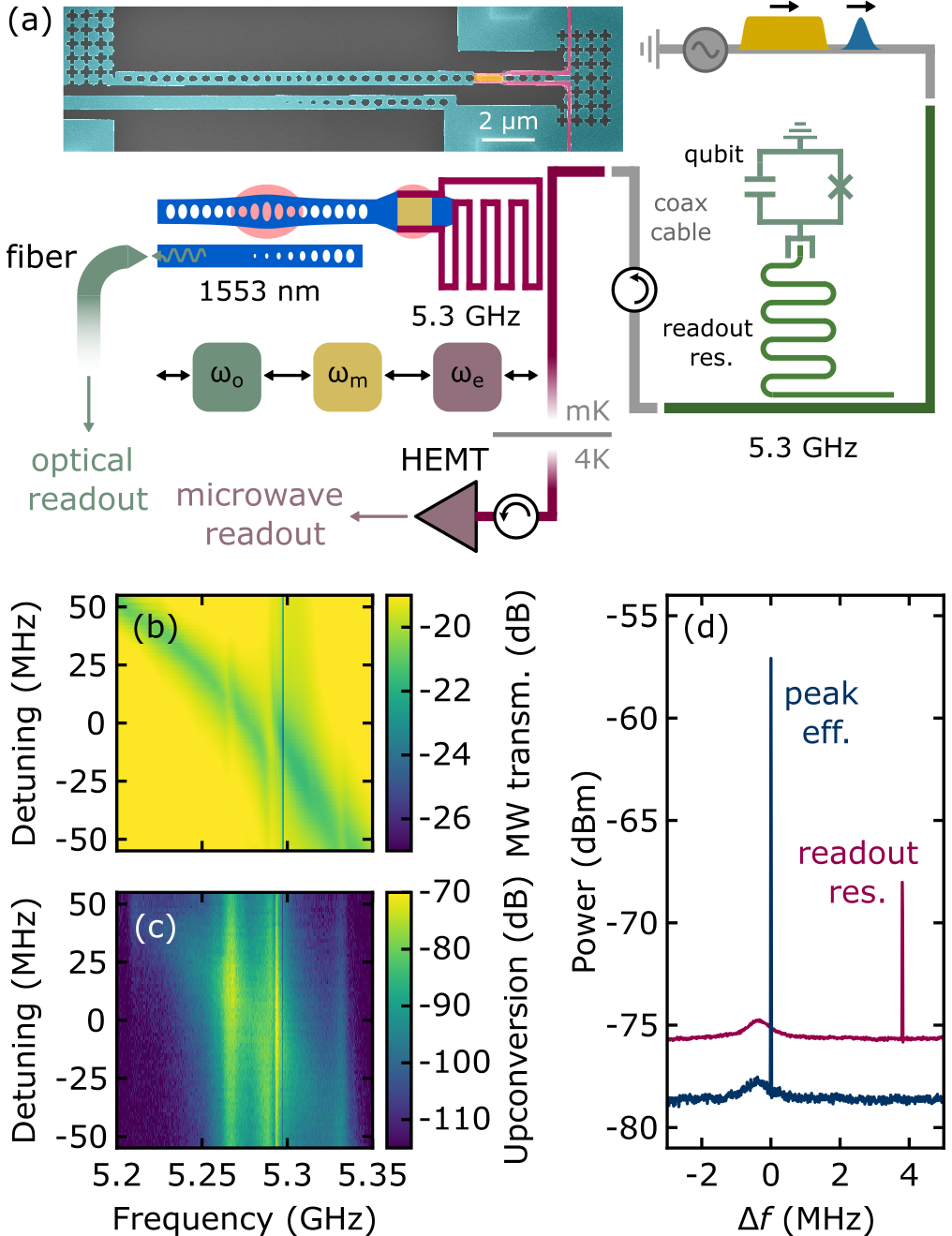
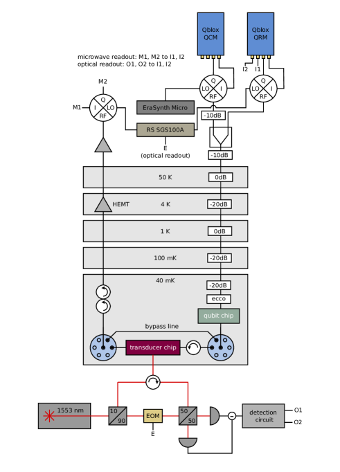
For our measurements we use a fixed-frequency transmon qubit hosted on a quantum integrated circuit (QuIC) test device [25] (qubit frequency ), which is operated using microwave readout and control pulses, and dispersively coupled to a co-planar waveguide resonator (readout resonator frequency ). The output port of the single transmission line used to drive and read out the qubit is coupled to the microwave transmission line of a transducer chip via coaxial cables. The transducer and qubit chips are physically separated by around and the latter is magnetically shielded through multiple cryoperm casings, which also reduce the probability of stray light reaching the superconducting qubit. An illustration of the experimental configuration is shown in Fig. 1a. Microwave readout signals are generated using a base-band Qblox Qubit Readout Module (QRM) and, after interaction with the qubit readout resonator, are upconverted by a piezo-optomechanical transducer operated with an optical pump tone red-detuned from the optical resonance (, ) by the mechanical resonance frequency . Approximately of optical pump power is transmitted into the cryostat, where the light is send towards the transducer via an edge coupler ( coupling efficiency). The total detection efficiency of the reflected optical signal is (see the Supplementary Information for further details). As discussed in previous work [24], the transducer incorporates a field-tunable microwave resonator to (i) resonantly enhance the electromechanical interaction with a \ceLiNbO3 piezoelectric block and (ii) facilitate efficient coupling to a transmission line.
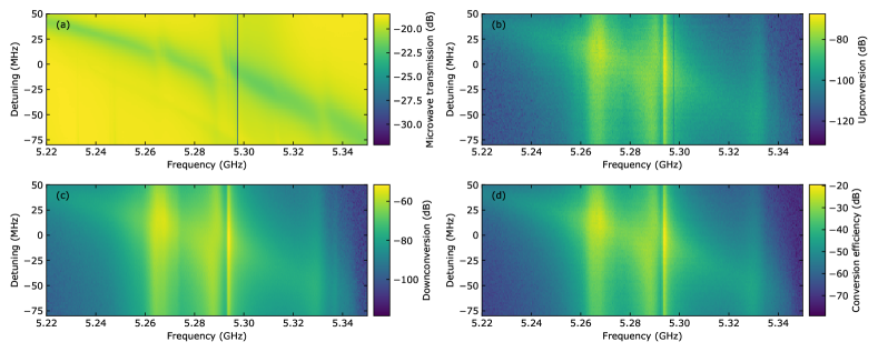
Fig. 1b shows the microwave transmission spectrum for different detunings of the transducer microwave resonator. The spectrum exhibits a dip at the qubit readout resonator frequency. The microwave signals are upconverted to optical light in the telecom range around via first the piezoelectric and second the optomechanical interaction, the latter driven by the red-detuned optical pump. The resulting signal is measured using optical heterodyne detection (Fig. 1c). Under these conditions, the device reaches a peak transduction efficiency of about at , which is decreased to when operated at the qubit readout resonator frequency. The dual peak feature in the upconversion spectrum can be attributed to the hybridization of electromechanically and optomechanically active mechanical modes in the transducer. Fig. 1d shows two recorded signal spectra under application of microwave tones at the readout resonator frequency as well as the frequency of peak transduction efficiency. At this optical driving power, the noise background is dominated by heterodyne shot noise, with only a small contribution of transducer resonant thermal noise, which can be seen as a broad peak centered at . The dominance of shot-noise, in particular away from the point of peak transduction, suggests that a larger optical pump power could further improve the signal-to-noise ratio (SNR). However, excess optical power can introduce thermal microwave photons which will cause qubit decay or dephasing via the AC-Stark effect [26, 21], quasiparticle generation [27, 28, 29] or mixing of transducer thermal noise with flux noise at the resonator-qubit detuning frequency [30].
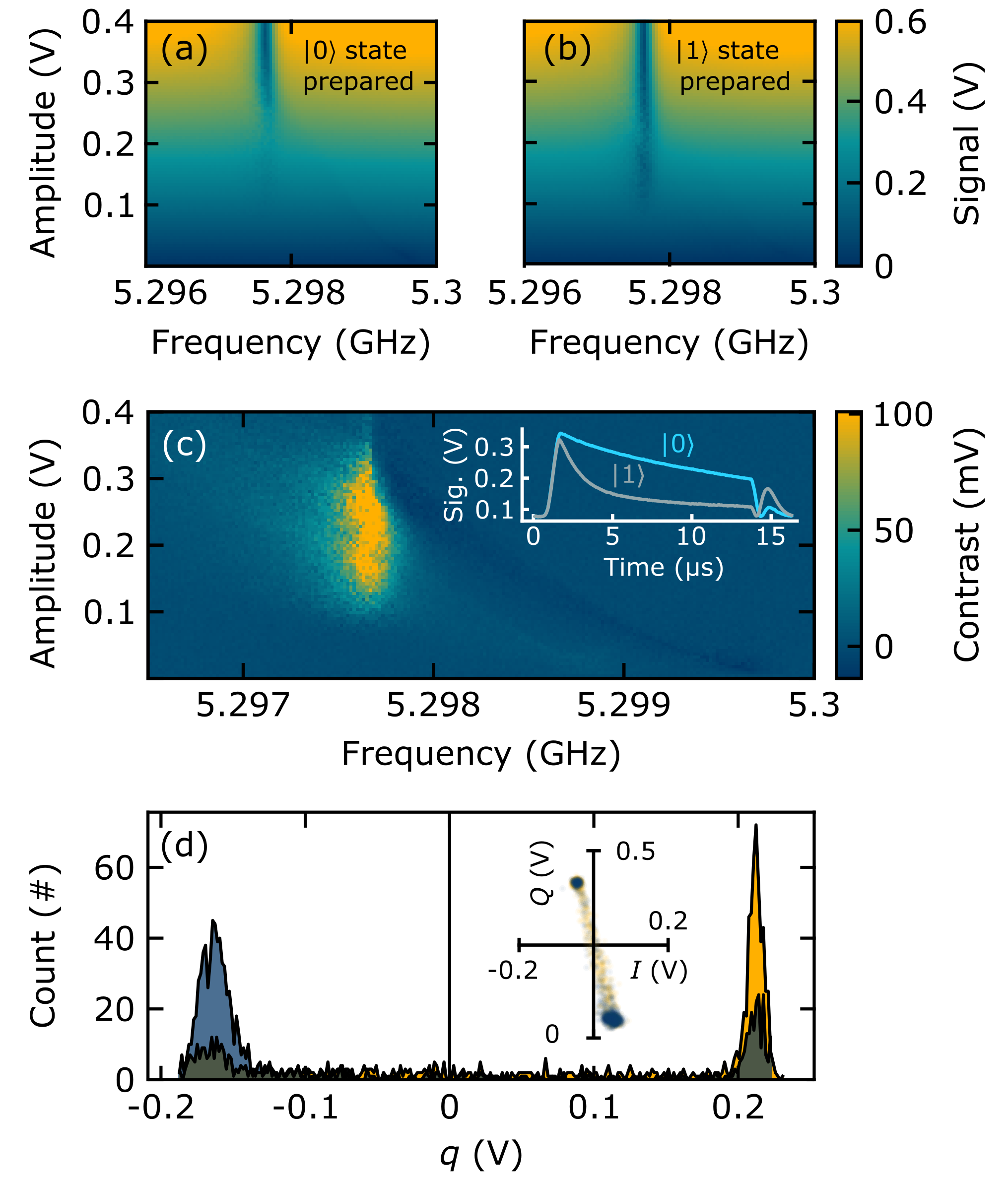
While non-demolition dispersive qubit readout is standard practice, it has been experimentally and theoretically demonstrated that demolition readout can be used with high fidelity in transmon qubits [31, 32, 33]. This approach exploits the occupation of higher level transmon states at large readout powers, which causes a qubit-state-dependence of the power at which the readout resonator enters the classical regime [32]. At such high readout powers, the signal is large enough to overcome typical amplifier noise at 4 K, enabling single-shot qubit readout without the use of a quantum-limited amplifier [31]. To define a benchmark for optical readout with a transducer, we therefore proceed by characterizing the high-power readout fidelity with microwave signals only, using a high-electron-mobility-transistor (HEMT) amplifier as the first element in the microwave signal-processing chain. Figs. 2a-b show the recorded microwave signal magnitude as a function of the frequency and amplitude of -long readout pulses with the and qubit states prepared, respectively. Optimal readout contrast is achieved at the bare readout resonator frequency at an amplitude level below the classical regime (see Fig. 2c). The inset of Fig. 2c shows averaged oscilloscope traces of the detected readout signals at the point of optimal magnitude contrast. We observe a shorter decay time of the transmitted microwave power when the qubit is prepared in the state, suggesting a faster avalanche-like transition of the resonator to its bare resonance frequency compared to the state [32]. To obtain maximum readout contrast, we choose a integration window starting at . Fig. 2d shows the statistics of 10,000 single-shot readout measurements, with the inset showing the individual data points in phase space. We optimize a linear decision boundary to determine the experimental readout fidelity defined as , which yields a value of . As expected, the fidelity is not limited by amplifier noise but by uncontrolled switching events. Such events, manifesting as a high effective qubit temperature, can occur due to suboptimal thermalization, or thermally out-of-equilibrium quasiparticles [34, 35, 36].
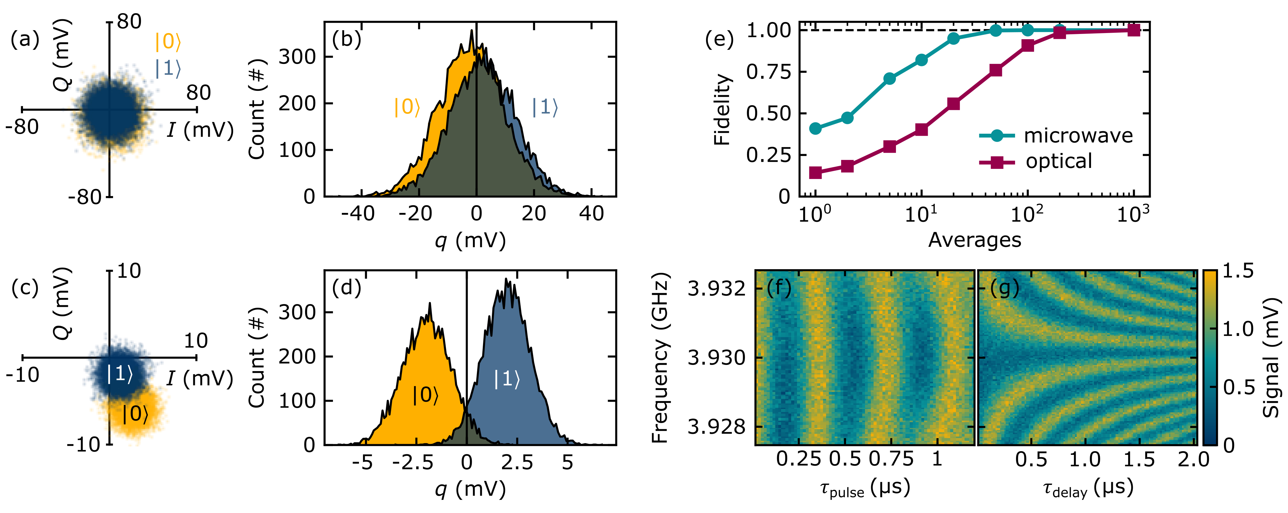
Having optimized the high-power readout pulse and set a benchmark for its performance, we now perform high-power optical readout using the configuration described in Fig. 1a. Using the same procedure as for microwave-only readout, we recover a single-shot optical readout fidelity of around after 10,000 measurements (see Figs. 3a-b). In contrast to the microwave-only fidelity, where uncontrolled switching is limiting, the fidelity for the optical readout is limited by the heterodyne shot noise due to the limited transduction efficiency and overall quantum efficiency of the optical detection, causing the clusters to largely overlap in phase space. The large cluster variances can be reduced by averaging, i.e. performing multi-shot readout. Figs. 3c-d show 10,000 multi-shot readout measurements with 100 averages per point, yielding a fidelity of around . Fig. 3e shows the fidelity as a function of the number of averages, comparing microwave-only and optical readout. For optical readout, a fidelity of can be achieved with 200 averages, compared to 20 averages for microwave-only readout. This result suggests that the SNR will need to be improved by approximately in order to match the microwave-only multishot readout, which is directly achievable either by using a stronger optical pump or improved frequency matching between the transducer and the readout resonator. Nevertheless, the fidelity is already sufficient to perform canonical qubit characterizations such as Rabi spectroscopy and Ramsey interferometry, which we show in Figs. 3f-g, respectively.
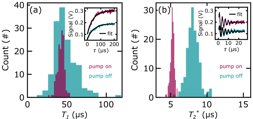
As discussed previously, at large optical pump powers, thermal microwave photons from the transducer may cause qubit decoherence. In a recent work, it has been shown that transverse qubit decay can be mitigated through implementation of sufficient isolation [21]. However, the necessity of adding a large number of isolators and filters might strain cryogenic space and thermal budgets, even in multiplexed optical readout scenarios. We therefore proceed to characterize qubit longitudinal and transverse decay times by measuring and with a single isolator inserted between the transducer and qubit readout resonator. The transducer microwave transmission output is sent to a HEMT microwave amplifier at 4K and used to determine the and decay times using microwave-only readout, comparing scenarios with the pump continuously on or off. To obtain a robust estimation, we perform 150 measurements for each scenario. Fig. 4a shows the distribution of the extracted times, with an inset illustrating two example curves and corresponding fits. We find a (statistically insignificant) reduction in from (pump off) to (pump on) . The reduction in variance could potentially be related to pump-induced thermal excitation of two-level systems in the qubit environment [37]. The difference in signal amplitude between the two scenarios, shown in the inset, can be attributed to a dependence of the transducer microwave resonator transmission on the optical pump power, which exhibits larger transmission with the optical pump on. The increased transmission has previously been shown to originate from the optical field inside the photonic cavity [24].
We further assess the impact of the pump on the transverse decay rate by measuring . Fig. 4b shows the statistical distribution of 150 measurements, with the inset illustrating two example traces. Again, we find a small but statistically significant reduction in from (pump off) to (pump on) . By implementing a duty cycle for the optical pump to reduce device heating and inserting additional filtering and isolation, balancing noise suppression with space constraints, we expect to be able to reduce and even fully avoid reductions in qubit decoherence times. A space efficient solution could be to include on-chip Purcell filters [38, 39, 40] and isolators [41].
In summary, we have demonstrated high-power optical qubit readout with a scalable integrated piezo-optomechanical transducer. In spite of imperfect frequency matching between the transducer and the qubit readout resonator, we are able to achieve high-fidelity multi-shot readout at only of optical power with as few as 200 averages, without the use of a quantum-limited parametric microwave amplifier. We note that, primarily due to the detuning of the qubit readout resonator from the frequency of peak performance, the transduction efficiency of the device considered in this work is approximately ten times smaller compared to previous work [24]. Accordingly, with closer frequency matching or increased transduction bandwidth, further device optimization and mitigation of losses in the optical detection chain, we will be able to increase the SNR by several orders of magnitude, bringing single-shot, high-fidelity optical readout of superconducting qubits within reach. Together with two other recent demonstrations on optical readout and control of a superconducting qubit [22, 23], our work sets a comprehensive new direction for reducing the space and heatload constraints on superconducting quantum processors.
I Acknowledgements
We gratefully acknowledge assistance from Emma He and the hospitality of the Department of Quantum Nanoscience at Delft University of Technology, as well as the Kavli Nanolab Delft. QphoX would also like to thank the European Innovation Council (EIC Accelerator QModem 190109269) for financial support. Qblox acknowledges support from the European Commission under Grant agreement 969201.
II Competing interests
T.C.T., M.J.W., F.B., P.D., M.L., K.L.S., M.Z., F.H., A.C.B., R.S and S.G. are or have been employed by QphoX B.V. and are, have been, or may in the future be participants in incentive stock plans at QphoX B.V. F.K.V., C.C.B. and J.O. declare a financial interest in Qblox B.V. J.Y.M., M.F., E.L., Y.M. are or have been employed by Rigetti & Co, LLC. J.Y.M., M.F., E.L., Y.M. are, have been, or may in the future be participants in incentive stock plans at Rigetti & Co, LLC.
III Data availability
Source data for the figures will be made available on Zenodo.
References
- Nat [2022] 40 years of quantum computing, Nat. Rev. Phys. 4, 1 (2022).
- F. Arute et al. [2019] F. Arute et al., Quantum supremacy using a programmable superconducting processor, Nature 574, 505 (2019).
- H.-S. Zhong et al. [2020] H.-S. Zhong et al., Quantum computational advantage using photons, Science 370, 1460 (2020).
- Brooks [2023] M. Brooks, What’s next for quantum computing (2023).
- Kjaergaard et al. [2020] M. Kjaergaard, M. E. Schwartz, J. Braumüller, P. Krantz, J. I.-J. Wang, S. Gustavsson, and W. D. Oliver, Superconducting qubits: Current state of play, Annu. Rev. Condens. Matter Phys. 11, 369 (2020).
- Chow et al. [2021] J. Chow, O. Dial, and J. Gambetta, IBM quantum breaks the 100-qubit processor barrier, IBM Research Blog (2021), accessed: 2023-06-07.
- Quantum AI, Google [2023] Quantum AI, Google, The quantum computing learning journey (2023), accessed: 2023-06-07.
- Rigetti Computing [2023] Rigetti Computing, Rigetti investor presentation (2023), accessed: 2023-06-07.
- Bluefors [2023] Bluefors, We made 1,000 qubits for quantum computing possible (2023), accessed: 2023-06-07.
- Preskill [2018] J. Preskill, Quantum Computing in the NISQ era and beyond, Quantum 2, 79 (2018).
- Mirhosseini et al. [2020] M. Mirhosseini, A. Sipahigil, M. Kalaee, and O. Painter, Superconducting qubit to optical photon transduction, Nature 588, 599 (2020).
- Han et al. [2020] X. Han, W. Fu, C. Zhong, C.-L. Zou, Y. Xu, A. A. Sayem, M. Xu, S. Wang, R. Cheng, L. Jiang, et al., Cavity piezo-mechanics for superconducting-nanophotonic quantum interface, Nat. Commun. 11, 3237 (2020).
- Han et al. [2021] X. Han, W. Fu, C.-L. Zou, L. Jiang, and H. X. Tang, Microwave-optical quantum frequency conversion, Optica 8, 1050 (2021).
- Wang et al. [2022] C. Wang, I. Gonin, A. Grassellino, S. Kazakov, A. Romanenko, V. P. Yakovlev, and S. Zorzetti, High-efficiency microwave-optical quantum transduction based on a cavity electro-optic superconducting system with long coherence time, Npj Quantum Inf. 8, 149 (2022).
- Meesala et al. [2023] S. Meesala, S. Wood, D. Lake, P. Chiappina, C. Zhong, A. D. Beyer, M. D. Shaw, L. Jiang, and O. Painter, Non-classical microwave-optical photon pair generation with a chip-scale transducer, arXiv.2303.17684 (2023).
- Jiang et al. [2023] W. Jiang, F. M. Mayor, S. Malik, R. Van Laer, T. P. McKenna, R. N. Patel, J. D. Witmer, and A. H. Safavi-Naeini, Optically heralded microwave photon addition, Nat. Phys. , 1 (2023).
- Lecocq et al. [2021] F. Lecocq, F. Quinlan, K. Cicak, J. Aumentado, S. Diddams, and J. Teufel, Control and readout of a superconducting qubit using a photonic link, Nature 591, 575 (2021).
- Pobell [2007] F. Pobell, Matter and Methods at Low Temperatures, ed. (Springer, 2007).
- MacDonald et al. [2015] A. MacDonald, G. Popowich, B. Hauer, P. Kim, A. Fredrick, X. Rojas, P. Doolin, and J. Davis, Optical microscope and tapered fiber coupling apparatus for a dilution refrigerator, Rev. Sci. Instrum. 86, 013107 (2015).
- Corcoran et al. [2020] B. Corcoran, M. Tan, X. Xu, A. Boes, J. Wu, T. G. Nguyen, S. T. Chu, B. E. Little, R. Morandotti, A. Mitchell, et al., Ultra-dense optical data transmission over standard fibre with a single chip source, Nat. Commun. 11, 2568 (2020).
- Delaney et al. [2022] R. Delaney, M. Urmey, S. Mittal, B. Brubaker, J. Kindem, P. Burns, C. Regal, and K. Lehnert, Superconducting-qubit readout via low-backaction electro-optic transduction, Nature 606, 489 (2022).
- Arnold et al. [2023] G. Arnold, T. Werner, R. Sahu, L. Kapoor, L. Qiu, and J. Fink, All-optical single-shot readout of a superconducting qubit, arXiv.2310.16817 (2023).
- Warner et al. [2023] H. Warner, J. Holzgrafe, B. Yankelevich, D. Barton, S. Poletto, C. Xin, N. Sinclair, D. Zhu, E. Sete, B. Langley, E. Batson, M. Colangelo, A. Shams-Ansari, G. Joe, K. Berggren, L. Jiang, M. Reagor, and M. Lončar, Coherent control of a superconducting qubit using light, arXiv.2310.16155 (2023).
- Weaver et al. [2023] M. J. Weaver, P. Duivestein, A. C. Bernasconi, S. Scharmer, M. Lemang, T. C. van Thiel, F. Hijazi, B. Hensen, S. Gröblacher, and R. Stockill, An integrated microwave-to-optics interface for scalable quantum computing, Nat. Nanotechnology (2023).
- [25] Rigetti quantum foundry services, https://www.rigetti.com/rigetti-quantum-foundry-services, accessed 14-08-2023.
- Schuster et al. [2005] D. Schuster, A. Wallraff, A. Blais, L. Frunzio, R.-S. Huang, J. Majer, S. Girvin, and R. Schoelkopf, ac stark shift and dephasing of a superconducting qubit strongly coupled to a cavity field, Phys. Rev. Lett. 94, 123602 (2005).
- Catelani et al. [2011] G. Catelani, J. Koch, L. Frunzio, R. Schoelkopf, M. H. Devoret, and L. Glazman, Quasiparticle relaxation of superconducting qubits in the presence of flux, Phys. Rev. Lett. 106, 077002 (2011).
- Catelani et al. [2012] G. Catelani, S. E. Nigg, S. M. Girvin, R. J. Schoelkopf, and L. I. Glazman, Decoherence of superconducting qubits caused by quasiparticle tunneling, Phys. Rev. B 86, 184514 (2012).
- Serniak et al. [2018] K. Serniak, M. Hays, G. De Lange, S. Diamond, S. Shankar, L. Burkhart, L. Frunzio, M. Houzet, and M. Devoret, Hot nonequilibrium quasiparticles in transmon qubits, Phys. Rev. Lett. 121, 157701 (2018).
- Slichter et al. [2012] D. Slichter, R. Vijay, S. Weber, S. Boutin, M. Boissonneault, J. M. Gambetta, A. Blais, and I. Siddiqi, Measurement-induced qubit state mixing in circuit qed from up-converted dephasing noise, Phys. Rev. Lett. 109, 153601 (2012).
- Reed et al. [2010a] M. Reed, L. DiCarlo, B. Johnson, L. Sun, D. Schuster, L. Frunzio, and R. Schoelkopf, High-fidelity readout in circuit quantum electrodynamics using the jaynes-cummings nonlinearity, Phys. Rev. Lett. 105, 173601 (2010a).
- Boissonneault et al. [2010] M. Boissonneault, J. Gambetta, and A. Blais, Improved superconducting qubit readout by qubit-induced nonlinearities, Phys. Rev. Lett. 105, 100504 (2010).
- Bishop et al. [2010] L. S. Bishop, E. Ginossar, and S. Girvin, Response of the strongly driven jaynes-cummings oscillator, Phys. Rev. Lett. 105, 100505 (2010).
- Wenner et al. [2013] J. Wenner, Y. Yin, E. Lucero, R. Barends, Y. Chen, B. Chiaro, J. Kelly, M. Lenander, M. Mariantoni, A. Megrant, et al., Excitation of superconducting qubits from hot nonequilibrium quasiparticles, Phys. Rev. Lett. 110, 150502 (2013).
- Geerlings et al. [2013] K. Geerlings, Z. Leghtas, I. M. Pop, S. Shankar, L. Frunzio, R. J. Schoelkopf, M. Mirrahimi, and M. H. Devoret, Demonstrating a driven reset protocol for a superconducting qubit, Phys. Rev. Lett. 110, 120501 (2013).
- Jin et al. [2015] X. Jin, A. Kamal, A. Sears, T. Gudmundsen, D. Hover, J. Miloshi, R. Slattery, F. Yan, J. Yoder, T. Orlando, et al., Thermal and residual excited-state population in a 3D transmon qubit, Phys. Rev. Lett. 114, 240501 (2015).
- Schlör et al. [2019] S. Schlör, J. Lisenfeld, C. Müller, A. Bilmes, A. Schneider, D. P. Pappas, A. V. Ustinov, and M. Weides, Correlating decoherence in transmon qubits: Low frequency noise by single fluctuators, Phys. Rev. Lett. 123, 190502 (2019).
- Reed et al. [2010b] M. D. Reed, B. R. Johnson, A. A. Houck, L. DiCarlo, J. M. Chow, D. I. Schuster, L. Frunzio, and R. J. Schoelkopf, Fast reset and suppressing spontaneous emission of a superconducting qubit, Appl. Phys. Lett. 96, 203110 (2010b).
- Jeffrey et al. [2014] E. Jeffrey, D. Sank, J. Mutus, T. White, J. Kelly, R. Barends, Y. Chen, Z. Chen, B. Chiaro, A. Dunsworth, et al., Fast accurate state measurement with superconducting qubits, Phys. Rev. Lett. 112, 190504 (2014).
- Sete et al. [2015] E. A. Sete, J. M. Martinis, and A. N. Korotkov, Quantum theory of a bandpass purcell filter for qubit readout, Phys. Rev. A 92, 012325 (2015).
- Chapman et al. [2017] B. J. Chapman, E. I. Rosenthal, J. Kerckhoff, B. A. Moores, L. R. Vale, J. Mates, G. C. Hilton, K. Lalumiere, A. Blais, and K. Lehnert, Widely tunable on-chip microwave circulator for superconducting quantum circuits, Phys. Rev. X 7, 041043 (2017).
- Xu et al. [2019] M. Xu, X. Han, W. Fu, C.-L. Zou, and H. X. Tang, Frequency-tunable high-Q superconducting resonators via wireless control of nonlinear kinetic inductance, Appl. Phys. Lett. 114, 192601 (2019).
- Rodrigues et al. [2019] I. Rodrigues, D. Bothner, and G. Steele, Coupling microwave photons to a mechanical resonator using quantum interference, Nat. Commun. 10, 5359 (2019).
- Andrews et al. [2014] R. W. Andrews, R. W. Peterson, T. P. Purdy, K. Cicak, R. W. Simmonds, C. A. Regal, and K. W. Lehnert, Bidirectional and efficient conversion between microwave and optical light, Nat. Phys. 10, 321 (2014).
Supplementary Information
IV Fabrication
The starting material for these devices is a film of X-cut \ceLiNbO3 (LN) bonded on an high resistivity silicon on insulator (SOI) substrate. The full device fabrication consists of four main parts. In the first one, an \ceAr milling process is patterning the LN layer to form small blocks. The second one involves the formation of the nanobeams using a reactive-ion etch (RIE) step. Afterwards, a deposition of a thick \ceMoRe layer fabricates the bondpads, the feedline, and the resonators. Finally, a buffered oxide etch (BOE) solution selectively etches the sacrificial \ceSiO2 layer underneath the Si device layer to suspend the devices. This step enables the oxide under the resonators to be removed and thus to increase the electrical quality factor of the devices. Further details regarding the fabrication is described in previous work [24].
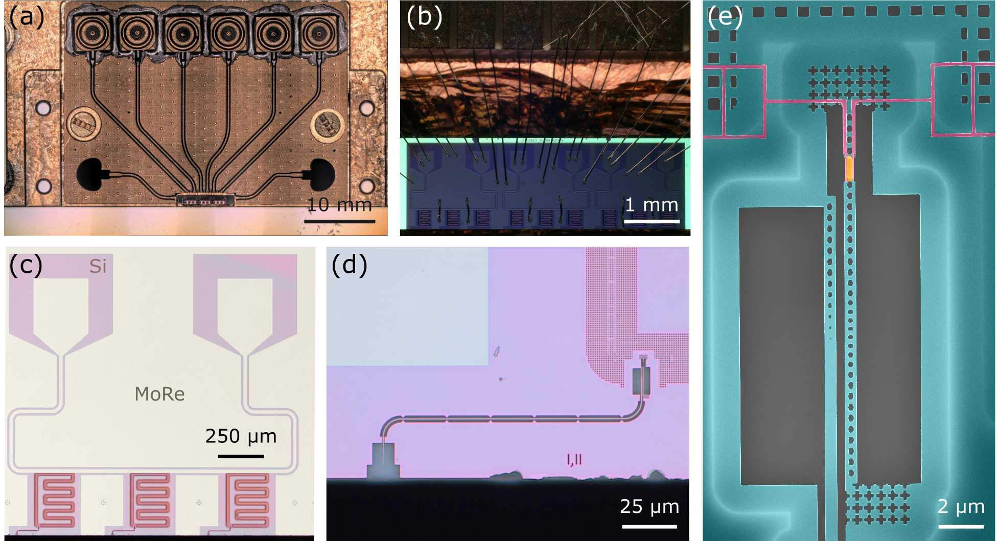
After fabrication, samples are mounted on top of a copper chip carrier using GE varnish (Fig. S1a) and the transducer microwave ports are wire bonded to electrical lines ending in soldered SMP connectors (Fig. S1b). Each microwave transmission line electrically multiplexes three transducer devices in hanger geometry (Fig. S1c). The optical port of the transducer device consists of a waveguide edge coupler at the edge of the chip, which can be coupled to with a lensed fiber (Fig. S1d). A SEM image of a representative transducer device is shown in (Fig. S1e).
V Transducer characterization
| Parameter Name | Description | Value | Error | Units |
| Transducer Property | ||||
| mechanical resonance frequency | 5.293 | GHz | ||
| optical resonance frequency | 193.029 | THz | ||
| frequency of peak conversion efficiency | 5.294 | GHz | ||
| mechanical linewidth | 534 | 5 | kHz | |
| total microwave loss rate | 11.35 | 0.46 | MHz | |
| microwave external coupling rate | 7.89 | 0.27 | MHz | |
| microwave internal loss rate | 3.47 | 0.19 | MHz | |
| total optical loss rate | 4.81 | 0.03 | GHz | |
| simulated vacuum optomechanical coupling rate | 573 | kHz | ||
| microwave resonator coupling | 0.347 | 0.01 | ||
| optical resonator coupling | 0.5 | 0.1 | ||
| Qubit Property | ||||
| bare readout resonator frequency | 5.2976 | GHz | ||
| dressed readout resonator frequency | 5.2996 | GHz | ||
| qubit frequency | 3.93 | GHz | ||
| readout resonator linewidth | 293 | kHz | ||
| qubit-resonator coupling | 48.1 | 0.1 | MHz | |
| dispersive shift | 410 | 20 | kHz | |
| Experimental Setup Property | ||||
| fiber coupling efficiency | 0.28 | 0.02 | ||
| optical output detection efficiency | 0.43 | 0.02 | ||
| total optical detection efficiency | 0.12 | 0.01 |
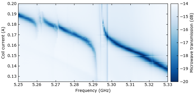
The (side-coupled) transducer microwave resonator consists of a wide superconducting wire, organized into a half-wave laddered comb-like loop (see Fig. S1c). The ladder subloops combined with the high kinetic inductance (around ) of the \ceMoRe superconducting layer allow for tuning of the resonance frequency, as described in ref. [42]. An external superconducting coil is mounted in close proximity to the transducer chip, yielding a field-to-current ratio of about at the sample. This leads to a tunability of typically several hundreds of and facilitates bringing the microwave resonator into resonance with the transducer’s optomechanically-active electromechanical mechanical mode. Fig. S2 illustrates tuning of the microwave resonance through several electromechanical modes.
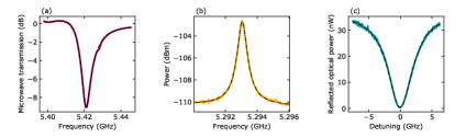
Fig. S3 shows the electrical, mechanical and optical resonances of the piezo-optomechanical system. To determine the external and internal electrical coupling rates, the microwave resonator is detuned from any electromechanical modes and its transmission spectrum is fit following the routine described in ref. [43] (see Fig. S3a). We find internal and external coupling rates of and , respectively i.e., an overcoupled resonator with a (side-)coupling coefficient of . The mechanical resonance of the optomechanical cavity is determined at , where it exhibits ample thermal motion. The GHz modulation of the hundreds of THz optical resonance by the thermally-excited mechanical mode is extracted through optical heterodyne detection, using a high-speed photodetector. The result is shown in Fig. S3b. We fit the data with a Lorentzian function, which yields a resonance frequency of with a total linewidth of . Note that, due to hybridization with the electromechanical mode of the \ceLiNbO3 piezoelectric block, the frequency of peak transduction efficiency () is slightly shifted from the mechanical resonance. Fig. S3c shows the optical cavity response, exhibiting a frequency of , linewidth of and waveguide-to-resonator coupling efficiency of , with a fiber-to-waveguide coupling of . The results are summarized in Table 1.
Following the approach of ref. [44], we characterize the transducer conversion efficiency with a four-port vector network analyzer (VNA) measurement (see Fig. S4). Upconversion is measured by applying a continuous microwave tone to the transducer electrical input port and demodulating the transduced optical signal using a heterodyne scheme incorporating a fast photodetector (Fig. S4b). The resulting microwave signal is collected by one of the two VNA input ports. Downconversion is measured through application of a microwave tone to an electro-optic modulator (EOM), generating optical sidebands on the red-detuned optical pump directed towards the optical input of the transducer (Fig. S4c). The transducer demodulates the composite optical signal to the microwave domain. The signal is subsequently amplified by HEMT and room-temperature low-noise amplifiers and collected by the other VNA input port. The transduction efficiency is calculated as
| (S1) |
where () is the upconversion (downconversion) and ()is the reflected microwave (optical) signal. The term corrects for a nonzero rejection of the lower optical sideband. The data reported here was recorded with a phase EOM, with the efficiency values calibrated by amplitude EOM measurements, following previous work [24]. As described in the main text, we extract conversion efficiencies of around and at (peak) and (qubit readout resonator), respectively at of optical pump power ( on-chip).
VI Experimental setup
The experimental architecture of microwave-only and optical readout is depicted in Fig. S5. In-phase and quadrature signals modulated at MHz frequencies are generated by a baseband Qblox Qubit Control Module (QCM) and used to drive the qubit following upconversion to the GHz domain by an I-Q mixer and RF local oscillator. The I-Q mixer is calibrated to reject the upper sideband of the composite microwave signal. A similar procedure is used to generate readout pulses with a Qblox Qubit Readout Module (QRM). We use a power combiner to transmit readout and drive signals towards the single feedline of the qubit chip. Using two cryogenic microwave switches, the signals emerging from the qubit chip can be directed towards either the electrical input port of the transducer (via a isolator) or to a bypass coaxial cable. From the second switch, the microwave signal is transmitted via two isolators towards a 4K HEMT and two room temperature amplifiers in series. Amplitude and phase information of the signal is then recovered via I-Q down mixing to baseband frequencies and subsequent demodulation by the numerically-controlled oscillator (NCO) of the QRM. For optical readout, the generation of microwave readout signals is identical to the procedure described for microwave-only readout, the only difference being that the RF local oscillator simultaneously drives an EOM in the local oscillator branch of a balanced optical heterodyne detection scheme, which downconverts GHz modulated optical signals to baseband frequencies. Using a custom detection circuit, in-phase and quadrature signals are extracted and demodulated by the NCO of the QRM. The time traces shown in the inset of Fig. 2c of the main text are acquired in oscilloscope mode using hardware-based averaging (10,000 averages). Remaining data from Figures 2 through 4 of the main text were acquired using on-board integration of the (unweighted) time trace values with the specified number of averages. The number of averages for the optical Rabi spectroscopy and Ramsey interferometry (Fig. 3f-g) measurements were 2,000 and 2,500, respectively. For the and traces (Fig. 4a-b), each datapoint was averaged 1,000 times.