Medusa: Scalable Biometric Sensing in the Wild through Distributed MIMO Radars
Abstract
Radar-based techniques for detecting vital signs have shown promise for continuous contactless vital sign sensing and healthcare applications. However, real-world indoor environments face significant challenges for existing vital sign monitoring systems. These include signal blockage in non-line-of-sight (NLOS) situations, movement of human subjects, and alterations in location and orientation. Additionally, these existing systems failed to address the challenge of tracking multiple targets simultaneously. To overcome these challenges, we present Medusa ***This is a preprint. Under review, a novel coherent ultra-wideband (UWB) based distributed multiple-input multiple-output (MIMO) radar system, especially it allows users to customize and disperse the into sub-arrays. Medusa takes advantage of the diversity benefits of distributed yet wirelessly synchronized MIMO arrays to enable robust vital sign monitoring in real-world and daily living environments where human targets are moving and surrounded by obstacles. Through our well-engineered hardware and software co-design, Medusa enables real-time processing of large distributed MIMO arrays while balancing the tradeoff between SNR ratio and spatial diversity gain across each of its four distributed 4x4 sub-arrays for increased robustness. We’ve developed a scalable, self-supervised contrastive learning model, which integrates seamlessly with our hardware platform. Each attention weight within the model corresponds to a specific antenna pair of Tx and Rx. The model proficiently recovers accurate vital sign waveforms by decomposing and correlating the mixed received signals—comprising human motion, mobility, noise, and vital signs. Through extensive evaluations involving 21 participants and over 200 hours of collected data (3.75 TB in total, with 1.89 TB for static subjects and 1.86 TB for moving subjects), Medusa’s performance has been validated, showing an average gain of 20% compared to existing systems employing COTS radar sensors. This demonstrates Medusa’s spatial diversity gain for real-world vital sign monitoring, encompassing target and environmental dynamics in familiar and unfamiliar indoor environments.
1 Introduction
Digital wellness and, in particular, passive health management and monitoring (i.e., without on-body devices) has steadily grown in popularity over the past decade, catering to numerous applications such as remote physical rehabilitation, vitals, and fall monitoring in indoor settings. These systems offer numerous advantages to both users and physicians. Users are unburdened by the correct usage and maintenance of sensor devices, allowing them to participate in daily activities freely. On the other hand, physicians can implement continuous patient monitoring protocols and facilitate proactive management.
There have been a lot of recent advances in wireless-driven passive health monitoring (PHM) and specifically contact-free Human Vital Monitoring (HVM) solutions, ranging from simple respiration rate monitoring (e.g., [7]) to more advanced biometric sensing solutions using various technologies (e.g., UWB [44, 13, 41], mmWave [16, 15], FMCW Radar [8], Wi-Fi [39, 24, 20]). While prevalent contact sensing technologies, including wristbands and chest vests, allow vital sign monitoring, such devices present limitations in prolonged use due to discomfort arising from contact with the skin and lack robustness in detecting moving human subjects.
For HVM, a shared characteristic of these studies is using wireless radar at higher mmWave frequencies (e.g., 60-77 GHz with 4 GHz bandwidth) to detect small (3.75 cm range resolution) body movements caused by respiration and heartbeats. Despite their potential, current radar-based vital sign sensing systems operate under controlled conditions, with human subjects remaining stationary in front of the radar transmitter and receiver, which constrains their performance in daily living conditions. These radar-based vital sign monitoring systems encounter challenges and degraded performance in real-world environments due to obstructions from human bodies blocking the radar path and the presence of obstacles in the surrounding environment. They also suffer from the limited field-of-view (FoV) and an operational range of 1-3m, due to small antenna arrays in current radars that struggle with significant signal attenuation.
The primary question posed in this research is: Is it feasible to transition radar sensing of biometric signals from restrictive deployments to practical "in-the-wild" operation, allowing for the monitoring of targets in their daily life habitats without sacrificing sensing performance? We make a substantial advancement in addressing this challenge by introducing our Medusa system, especially for moving human targets and dynamic environments.
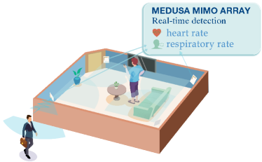
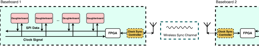
The core intuition behind Medusa is to leverage the diverse signal paths and perspectives enabled by spatially distributed MIMO radar arrays for sensing, akin to distributed MIMO operations for communication as shown in Fig. 1. To achieve robust spatial diversity, we utilize multiple distributed MIMO subarrays deployed in real-world living environments, unlike existing radar-based vital sign monitoring systems that rely on single commercial off-the-shelf (COTS) radar units. Such single radar systems can only capture partial vital sign information as people change orientations, while our distributed MIMO approach allows the gathering of multi-aspect data.
While distributed MIMO array contributes to a throughput improvement in communication systems, it can potentially deliver a much more profound impact for wireless sensing – going from constrained operation to enabling practical, "in-the-wild" sensing operation that is robust and immune to varying target locations, orientations, blockages, and mobility. While we focus on HVM as our application, our core system contributions apply to the broader space of biometric sensing with wireless signals. Towards realizing this objective, we present Medusa– a large systems effort towards addressing the following key challenges, leading to its contributions:
1. Distributed Radar System: How do we create a practical, distributed MIMO radar system that has sufficient gain to operate in real-time and reliably for practical room-scale deployments? While UWB and mmWave radar systems offer high resolution (1-2 GHz bandwidth), radar sensing being an inherent mono-static system, offers very limited operational range (less than 3m) with today’s systems that have limited arrays (e.g., elements virtual mmWave array [1]). This is further compounded by the potential interference that arises when distributed radars transmit simultaneously without tight synchronization – a feature that is hard to accomplish, yet important for a coherent MIMO system; the lack of which, leads to confounding and corrupting the received target signals with other reflections.
C1. Medusa builds a first-of-its-kind 256 (16x16) element virtual MIMO system for a high-gain UWB-based radar sensing (shown in Fig. 2). UWB’s better penetration capability (3-10 GHz) compared to mmWave, coupled with the large antenna gain in Medusa, allows us to detect targets as far as 6m even in NLoS reliably. The modular design features a two-tone wireless synchronization method resistant to multipath interference, enabling a flexible, reconfigurable, and distributed radar system. It allows the large MIMO subarray to be divided and dispersed throughout the environment, providing diversity in target locations and orientations while maintaining synchronization between sub-arrays to avoid interference. This allows Medusa to cater to different room configurations, where different levels of diversity may be better suited: either deploy the entire 256 virtual MIMO system in one location in a small, narrow corridor or spread them as virtual MIMO system in different locations in a large room, or other flexible, asymmetric combinations in between without much effort. Medusa’s hardware architecture is cost-effective, yet real-time, where each of its sub-arrays brings together a set of commodity UWB radar chips while designing its own Vivaldi antennas needed for an optimized radiation pattern along with an FPGA for real-time processing and inference of the subarray’s received signals. We also employ wireless synchronization channels between MIMO sub-arrays to maintain clock signal coherence across different baseboards. The conventional multiple radar synchronization systems are designed for Unlike previous research on wireless clock synchronization [9, 6], which utilizes custom-designed front-end hardware, we have developed a high-precision wireless coherency subsystem specifically for synchronizing the timing of multiple MIMO radar baseboards (sync channel) by using COTS development modules and the Mixed-Mode Clock Manager (MMCM) on FPGA.
2. Balancing MIMO SNR Gain vs. Spatial Diversity Gain: While distributed MIMO systems for communication have been explored, as detailed in [10], it is unclear how to distribute MIMO radar processing to deliver robustness for sensing. However, dispersing the MIMO array into various sub-arrays can amplify spatial diversity gain, even if the SNR of individual sub-arrays reduce. In particular, we need to revisit the popular tradeoff between antenna gain for SNR vs. the diversity gain for outage probability as it applies to sensing: While using the entire 256 virtual MIMO gain at a single location offers the most gain/coverage from that subarray’s perspective, it is not robust to sensing diverse orientations and locations of the target as well as handling NLoS and blockages, not to mention operation under target motion. On the other hand, distributing the virtual MIMO gain by splitting and distributing the sub-arrays across multiple locations provides robustness to ‘in-the-wild’ target configurations but comes at the expense of reduced antenna gain and coverage at each sub-array. The challenge lies in efficiently managing this tradeoff to provide accurate sensing performance that remains robust across a wide range of target and environmental conditions.
C2. Through extensive experimental characterization, Medusa identifies an ideal operating point, wherein one sub-array per quadrant around the target area strikes the most effective balance – any further distribution only reduces the gain per sub-array without adding appreciably to the diversity gain. In contrast, less diversity diminishes the robustness in sensing performance. In particular, Medusa employs four sub-arrays, each with 16 virtual MIMO elements, to establish its distributed radar system for rooms. This configuration also offers flexibility to adapt to other room shapes.
3. Scalable Signal Extraction: While Medusa enables a high SNR sensing signal agnostic to target and environment configurations, it is still a hard challenge to isolate the vital signals mixed with numerous other reflections (distortions from human motion, multipath, etc.) in a non-linear manner. Machine learning offers a scalable approach to extract our desired signal, given its recent success in several wireless sensing problems [16, 13, 44, 15, 37]. However, supervised learning approaches exhibit strong data dependence and require extensive labeled data collection for each new individual, limiting generalizability across different human subjects. Furthermore, every environment leaves its artifacts in a dataset, significantly affecting the model’s generality when tested on unseen environments with different configurations.
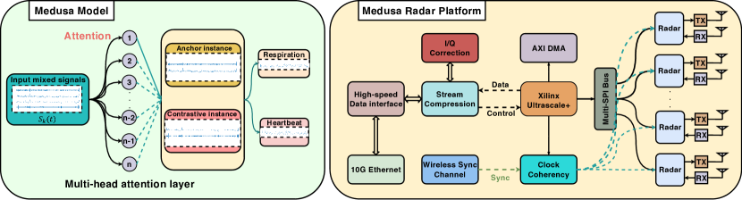
C3. Medusa leverages the recent advances in contrastive learning to devise a self-supervised approach to extracting human vital signals. However, to leverage the diversity offered by the distributed sub-arrays, Medusa instruments contrastive learning with a multi-head attention mechanism that allows the model to appropriately and implicitly attend to the different sub-arrays based on the estimated location and orientation of the target as well as the configuration of the environment (blockages). The lack of ground truth requirement afforded by contrastive learning, coupled with its distributed array attention, enables Medusa to estimate vital signals of targets ‘in the wild’ in a highly scalable manner. Further, its robustness to target and environment configurations also allows it to track these signals in the presence of target motion, as well as extend to multiple targets, both being useful features for practical deployments that is hard to accomplish with existing approaches. It is worth mentioning that while Medusa’s self-supervised approach intelligently combines the signals from the distributed sub-arrays to extract the desired target signal, the underlying distributed MIMO radar in Medusa plays a critical role in delivering signals of high SNR that are robust to targets and environments, posing less burden on the ML model to overfit itself to the trained targets and environments. This, in turn, allows Medusa to scale better to unseen environments and targets.
To the best of our knowledge, this system is the first of its kind designed for real-time vital sign monitoring, exhibiting the capability to function proficiently within dynamic real-world contexts. Our contributions to this work can be summarized as follows:
We design and build an innovative 256-element virtual MIMO radar system, Medusa, that enables flexible, coherent, and distributed radar sensing. This cutting-edge system provides robustness for various target and environmental configurations and features chip-level wireless synchronization capabilities for practical and flexible deployment.
We characterize the tradeoff in coverage vs. sensing robustness experimentally to determine the most efficient distributed mode of operation for optimized sensing performance.
We design a self-supervised learning approach that effectively leverages the diversity of the distributed radar sub-arrays automatically to extract the desired target breathing signals in various target and environment configurations while allowing for target motion inherent to everyday tasks.
Our comprehensive evaluation with 21 participant subjects reveals that Medusa improves median HVM accuracy by over 20% compared to prior art and baselines in practical indoor environments, characterized by varying subject locations and orientations, and sustain errors under 5% even in NLoS (obstacles) conditions, where other approaches falter. Further, leveraging the diversity benefits of its distributed platform allows its model to (generalize) sustain performance accuracy even in unseen environments, subject mobility as well as multiple subjects.
We believe Medusa is one of the first systems to expand the scope of wireless HVM solutions by making them robust to various target and environment configurations. In addition to bringing these solutions closer to practical adoption, it opens the door for exciting follow-up work in distributed radar sensing and networking.
2 Related Work and Motivation
In this section, we examine prior art in wireless-based passive health sensing (PHM), and motivate the benefits of distributed multiple-input, multiple-output (MIMO) array-based sensing systems over traditional co-located sensing solutions.
2.1 Related Work
Real-world applications demand robust human vital monitoring systems resilient to changes in target position, range, orientation, motion, as well as environmental factors like line-of-sight (LoS) and non-line-of-sight (NLoS) blockages.
RF-based health sensing: Research has made significant advances in using RF to passively (contact-free) sense people and their vital signs (i.e., human breathing and heart rates).
Radar sensing: Researchers in [16, 13, 44, 42, 41, 14, 15] have leveraged the large channel bandwidths available in UWB and mmWave bands to passively capture human breathing and heart rate. However, with most of these solutions employing either the COTS UWB radar [3] with a single Tx/Rx antenna that the operational range is limited to only 3-5m distance, and some of the work the mmWave radar array (4 Tx, 3 RX [1]) operating at a high (75GHz-77GHz) frequency, even in LoS and within a narrow FoV of 50deg, making these solutions inadequate for practical room-scale deployments, especially with NLoS. Moreover, having a single radar additionally constrains the target to be oriented in a particular direction (e.g., facing the radar) to measure the physiological movements accurately.
On the other hand, solutions [19, 22, 32] that use two single-antenna radars, or a single radar with two antennas [29], require the two elements to be placed at specific locations with respect to a human body (e.g., front and back of a target) to eliminate signal-blockages caused by human action and body orientation, providing the simplest form of diversity, but are unable to offer practical ranges or NLoS operation with single antenna elements. Other solutions [18, 7, 23, 35, 43, 15, 38] that use COTS devices, while capable of measuring vitals of multiple targets within an enclosed space, can do so only when the targets are reasonably stationary and facing the radar in LoS. In [15], the approach of using COTS mmWave sensor takes advantage of a well-established correlation between HR/RR and motion intensity, moving away from the traditional time-frequency analysis, which is often disrupted by motion. However, it faces challenges in non-line-of-sight (NLOS) conditions and multiple targets. Additionally, DeepBreath [38] introduced a method that employs linear ICA to decompose respiratory signals from multiple individuals who remain stationary, such as those asleep in set positions.
Wi-Fi sensing: The WiFi-based sensing solutions [39, 20, 40, 24] rely on Channel State Information (CSI) to capture the minute displacements on a human body - E.g., a human diaphragm’s expansion-and-contraction during breathing. However, with CSI being extremely sensitive to the environment, these solutions need extensive calibration and fingerprinting, making them impractical for in-the-wild deployments.
Non-RF based health sensing: In addition to RF-based sensing, researchers have explored acoustic [31, 33, 34, 28] and camera-based[12, 25, 36] solutions to monitor breathing and heart rates, respectively passively. However, they require targets to be relatively static in LoS, facing the radar and are impacted by background noise and human motion.
To the best of our knowledge, existing solutions cannot simultaneously cater to the different dimensions of target and environment dynamics, which are central to delivering a robust and practical HVM solution. Medusa takes an important step in this direction towards robust HVM sensing.
2.2 Case for Distributed MIMO Sensing
The high-level idea of Medusa is to strike a tradeoff between MIMO antenna gain for SNR vs. the spatial diversity gain for dynamic environment. To better motivate the design of Medusa, we conducted motivational experiments to concretely demonstrate the challenges faced by wireless human vital sign monitoring.
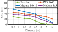
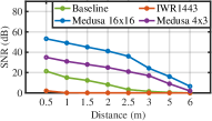
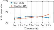
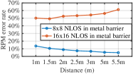
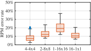
Limited Operating Range: Commodity-of-the-Shelf (COTS) UWB radar sensors used in previous studies [13, 44, 41] have a SISO configuration. Compared to a SISO system, MIMO radars provide better spatial resolution and a higher SNR gain (increased coverage) in both LoS and NLoS (behind a wall) conditions. This is evident in Figures 3,6, where a 16x16 (256-element virtual) radar provides an SNR gain of 10-30 dB, with a relatively higher gain in NLoS, which is especially vital in extending practical operational ranges to over 6m and directly contributes to about 30% increase in RPM accuracy, keeping errors to under an acceptable rate of 10%. While the mmWave MIMO radar delivers a good SNR in LoS, its performance degrades significantly in NLoS (40% error) even compared to a UWB radar.
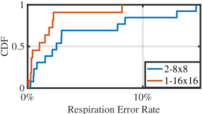
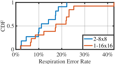
Limited Coverage of Co-located MIMO Radars: While MIMO antennas improve SNR and coverage of a radar’s aperture, their ability to illuminate the target and obtain sufficient reflections diminishes significantly when the target is not oriented front-facing the radar. On the other hand, a spatially distributed MIMO system will provide the necessary spatial diversity for vital monitoring irrespective of the target’s distance and orientation. The result in Fig 6 highlights that distributing the 16x16 modular array into two 8x8 arrays (placed at 90 degrees to each other) sacrifices some accuracy (median error still under 5%) compared to a single 16x16 array when the target is facing front. However, its diversity proves valuable in sustaining the error performance to under 10% even in other target orientations, while the 16x16 array’s performance degrades to over 20% error.

While it is impossible to eliminate the blockage of a centralized MIMO array (for instance, when a metallic object in the living room, such as a refrigerator, obstructs the signal path, causing 6-7 dB attenuation), distributed MIMO arrays with multiple viewpoints can still operate effectively, by increasing the probability of an unobstructed path.
Lack of Robustness to NLoS Targets: The result in Fig 7 illustrates a real-world deployment scenario with furniture and obstructions (e.g., metal barrier) in the room space. It highlights the substantial performance degradation of co-located radar systems in such situations, with a notable error rate of over 50%. Current systems typically do not account for these challenging environments, where the distributed radar system excels in performance. As the non-line-of-sight (NLoS) distance to the first radar increases, the line-of-sight (LoS) distance to the second radar reduces, leading to the overall efficacy of the distributed radar system.
2.3 Medusa Design Challenges
While our experimental study motivates the need for a distributed MIMO radar for robust HVM across target and environment dynamics, realizing such a system is challenging.
Synchronization and phase coherency: In developing an active MIMO radar system, it is imperative to guarantee synchronization of each radar element that operates with its own independent transmit/receive (TX/RX) chain. This poses a challenge in hardware design, where the system must provide adequate gain across all the distributed subarrays, while concurrently synchronizing them, lest leading to interference and degradation of target SNR and consequently obscured by additional reflections. Although challenging, high-precision, over-the-air clock synchronization is crucial for scalable deployment and operation of distributed MIMO arrays.
Balancing SNR vs. Diversity: As seen in the study, while large MIMO arrays (e.g., ) increase the SNR and hence the coverage of the radar, they fail to bring robustness to sensing in practical scenarios. In contrast, while spatially distributing a large MIMO array into several smaller sub-arrays brings much-needed diversity, over-distribution can significantly reduce the gain and coverage per aperture without adding diversity appreciably. A careful balance of the tradeoff between coverage and sensing robustness need to be addressed in determining an efficient distribution of MIMO sub-arrays for sensing.
Real-time and Robust Vital Sign Signal Extraction: To realize the true potential of distributed MIMO sensing for robustness towards target and environment dynamics, we need a scalable approach that can leverage and effectively fuse signals from the distributed sub-arrays to accurately extract the human vital signal from a complex non-linear mixture with other undesired signals (e.g., human motion, multipath reflections) in real-time.
Medusa addresses these challenges by building a MIMO UWB radar sensing with accurate time synchronization for distributed radar elements in real-world situations and a self-supervised learning model.
3 System Design
Medusa is a modular platform that enables flexible deployment for optimal performance in a wide range of environments. Multiple radar sensors, each of up to 16x16 array size, can be distributed to cover an area in its entirety while guaranteeing fully coherent distributed MIMO sensing across all radar sensors. Motivated by the observations made in Sec. 2, we now describe Medusa’s original hardware design, its efficient deployment and operation, and tightly integrated software models that leverage its distributed deployment.
3.1 Medusa Hardware Design
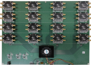
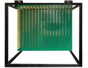
Medusa consists of a baseboard onto which multiple RF daughterboards (up to 16). Each daughterboard is built around a Novelda X4 UWB radar chip [3] which drives one Tx and one Rx antenna. With these antennas arranged in a 2D grid, Medusa utilizes up to 256 (i.e., 1616) antenna elements in a virtual radar array. These antennas are mounted on a separate antenna board that is connected to the daughterboard via RF cables. These different components of Medusa are shown in Fig. 9.
3.1.1 Medusa Radar Baseboard
The radar baseboard comprises a Xilinx Zynq UltraScale+ MPSoC FPGA [5] and socket interfaces for 16 radar daughterboards. Each socket is connected to the Zynq FPGA via 16 SPI buses and a pair of differential RF clock lines. This fan design enables significant operating flexibility across the daughterboards: all 16 daughterboards to be operated as a single coherent MIMO radar; alternatively, the daughterboards can be divided into subgroups of smaller MIMO radars, with each subgroup operating independently of the others.
Timing skews within the clock signals and SPI to the daughterboards must be eliminated to ensure coherent MIMO radar operation. Medusa distributes a phase-coherent 243MHz Low-Voltage Differential Signal (LVDS) clock signal from the Zync FPGA to all attached daughterboards over the differential RF lines to eliminate clock noise and interference. Impedance matching is also carefully calibrated to ensure equal clock and SPI line lengths, further reducing any timing skews in the hardware.
For coherent MIMO operation, Medusa must also ensure coherence across the internal state of all X4 UWB radar chips. Medusa’s FPGA processes all SPI commands with the X4 chips concurrently to force the internal state of the separate X4 chip to operate in lockstep. Together with the careful clock distribution logic, this guarantees coherent sampling of the MIMO RF signals across all daughterboards. Finally, the baseboard streams I/Q data from all daughterboards, in real-time, to a host PC via a 10GbE Ethernet connection.
3.1.2 Medusa Daughterboard
Each daughterboard is built around a Novelda X4 chip [3]. The daughterboard routes differential clock signals and SPI commands from the baseboard to the X4 chip and forwards I/Q data from the X4 radar back to the baseboard, all with minimal time delay. Each daughterboard is physically pluggable into the baseboard via an 18-socket interface.
3.1.3 Medusa Antenna Design
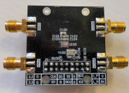
Each daughterboard drives one Tx and one Rx antenna. To minimize errors in vital sign monitoring, Medusa employs custom high-gain directional Vivaldi antenna elements that provide optimal SNR for radar returns, as shown in Fig. 9(e). The Novelda X4 chip employs differential RF lines for TX and RX, requiring differential antennas. These antennas are connected to the daughterboard using SMA connectors.
3.2 Wireless Clock Synchronization
Within radar and remote sensing domains, efforts have been made to synchronize multiple radar systems over the years [27, 11]. However, these approaches are not well-suited for indoor distributed MIMO array systems wireless synchronization due to the high hardware expenses. Furthermore, the Novelda X4 chip operates at a higher clock signal frequency, rendering conventional multiple radar synchronization systems ineffective.
Medusa uses multiple baseboards with several daughterboards and antennas to achieve distributed MIMO sensing within an area of interest. To maintain MIMO coherence even between daughterboards not physically connected, Medusa uses wireless clock synchronization to ensure clock tick coherency between these separate baseboards.
Each baseboard features a COTS Software-Defined Radio (SDR) module, which utilizes an AD9361 transceiver to transmit and receive wireless clock signals. Ad9361 has two RF chains for 2 TXs and 2 RXs. Clock distribution is organized into a server-client design. One of the baseboards is designated as the clock server, while all others are the clock clients. Clock signals are transmitted from the server baseboard to all the client baseboards.
Fig. 10 shows the clock generation design for each client. The wireless clock signals received by the client are sent into a phase-locked loop (PLL) which “cleans-up” the noisy wireless clock signal. Coherent MIMO requires that the phase of this signal be aligned at all the client baseboards. Nonetheless, the RF propagation distance between the server and the client influences the clock signal phase. A phase-offset correction is applied to obtain a clean reference clock signal, which is subsequently used to clock the X4 chip during standard operation.
3.2.1 Clock Distribution
The wireless clocks signals suffer from carrier frequency offset (CFO) due to the minute clock differences between the server and client baseboards. To correct this, the clock signals are transmitted as differential two tones of frequencies signals. Instead of transmitting a single clock signal, two different clock signals at frequencies and are sent. These are received at the client as and where is the CFO between the server and client transceivers. The client baseboard then derives the final reference clock from the difference of these two received signals, , that are no longer affected by the CFO.
In practice, this is accomplished by the circuit shown in Fig. 10. The minimum valid reference clock for the X4 chip is 9MHz. Hence, the server transmits and signals to the clients. These signals are amplified (LNA) and filtered (bandpass) before passing through a mixer that generates and . A follow-up bandpass filter eliminates the higher frequency component, leaving only the signal that is passed into the clock generation circuit of Fig. 10. This circuit uses the PLL and Mixed-Mode Clock Manager (MMCM) components in the ZYNQ FPGA.
3.2.2 Phase Offset Correction
The phase of this downstream wireless clock signals at each client is subject to a phase offset dependent on the RF propagation distance between the server and client device. To eliminate this offset, the client devices transmit upstream differential clock signals to the server. These upstream clock signals are generated using the downstream reference clocks and thus suffer from the same phase offset as the downstream clock signal.
The server, having received the upstream clock from each receiver, can determine the relative phase offsets between the clients. This phase offset is communicated to the clients. The clients apply the phase offset correction, as shown in Fig. 10, thus ensuring phase coherence across all clients. We note that the phase offset between the server and clients is still unknown and cannot be determined with this approach. In regular Medusa operation, the server thus does not participate in distributed MIMO sensing with the clients. It can operate its baseboard+daughterboards in a local MIMO configuration, independent of the other Medusa radars.

3.3 Deploying Medusa- Diversity Vs SNR
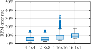
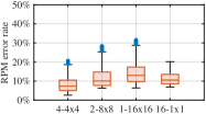
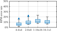
For Medusa to be successful, it is crucial to find an optimal balance between diversity gains, achieved by spatially distributing the radars, and SNR gains, achieved by co-locating MIMO antennas. We conduct thorough experiments leveraging the Medusa’s modular design to deploy various MIMO radar configurations (e.g., one , two , four and sixteen radars) and evaluating the measured RPM accuracy with a static target positioned at different indoor locations (see Fig19). (Details on ground truth and data collection can be found in sec4). Fig 11 shows a subset of our experimental results. In LOS conditions, when the target is close to a radar (e.g., 1m), the configuration delivers the best performance due to its high SNR gains. However, when the target moves away to 5m, the configuration experiences a decline in accuracy as the SNR decreases, resulting in a respiratory error rate of 12.94%. Meanwhile, the spatially distributed four and two configurations together help compensate for the SNR loss at individual radars. In NLOS scenarios, the centralized radar suffers SNR degradation due to blockage and performs poorly. On the other extreme, the sixteen arrays benefit from spatial distribution but the single antennas do not see any SNR benefits and have median RPM error of 9.4 % at 1m and 10.5% at 5m. The four configuration, on the other hand, offers the best trade-off (median RPM error 5.8%) between SNR and diversity gains and performs the best. Consequently, Medusa adopts the four configuration.
3.4 Human Vitals Sensing with Medusa
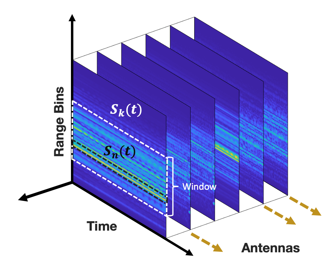
The X4 chip uses UWB time-of-flight pulses to measure ranges. With each UWB pulse, the X4 chip returns a 186-bin range measurement, with each bin containing the amplitude and phase of a reflected signal from the indicated distance. Fig. 12 illustrates the returned range data from multiple daughterboard antennas over time. Changes in human activities and vitals (e.g. breathing, heart beats etc) will induce changes in the reflected signals captured in each radar frame. This is inter-mingled with signal reflections due to other movement in the environment, along with multipath distortions. These radar frames are encoded as I/Q data streams and transmitted over the 10GbE link to an external PC, where Medusa employs a self-supervised ML model to separate RF changes due to human vitals from those due to other unrelated activities.
| Medusa | IWR1443BOOST | AWR2243 Cascade | |
| Frequency Band | 6.5-9.5GHz | 76-81 GHz | 76-81 GHz |
| TX/RX | 16TX/16RX | 3TX/4RX | 12TX/16RX |
| Azimuth Array | 256 element virtual array | 12 element virtual array | 86 element virtual array |
| Max Angular Resolution | 0.448 degree | 9.53 degree | 1.4 degree |
| Min Spacing Separation | 0.039m at 5m | 0.841m at 5m | 0.122m at 5m |
| Frame Rate (FPS) | 50 – 200 | 10 | 5 |
3.4.1 Extracting Human Vitals
Medusa recovers the human vital signals mixed with other interfering signals using independent component analysis (ICA). Consider a single radar receiver, . Let be a vector of the source signals induced by human respiration, heartbeats, and motion for one or more monitored individuals. These signals are combined in a non-linear fashion at the radar sensors as
| (1) |
where the is the received signals at the radar receiver. In Medusa, these signals arrive in different range bins.
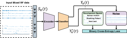
The objective of non-linear ICA is to find the inverse to recover from . To do this, we employ a contrastive learning model, as shown in Fig. 13, where the model function approximates the intended ICA output .
In Medusa, represents a window of range bins from receiver at some time , where . We generate positive and negative samples from for contrastive training, defined as
| (2) |
where is a constant and is a randomly selected time offset.
Let be the encoder used in the contrastive model. If we train the model to discriminate between and , we obtain the representation of [17]. Note however, our model does not yet account for coherent radar signals from multiple Medusa receivers. To this end, Medusa uses a multi-head attention step in its self-supervised model.
3.4.2 Multi-Receiver Fusion
Instead of utilizing the received signals from each antenna directly, Medusa uses a multi-head attention layer to fuse signal information from all radar receivers before training dynamically:
| (3) |
where is the number of heads in the attention layer [30], and is the attention layer function that maps radar receiver signals into head outputs. We then train the contrastive model to discriminate between and of each head output .
3.4.3 Features and Vital Signs Identification
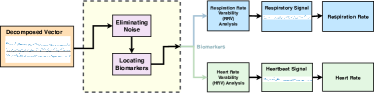
After the training step, Medusa extracts the independent signal components by collecting the output of for . These signals, as mentioned earlier, consist of human vital signals and radar returns due to human mobility. Medusa identifies the breathing and heartbeat signals by analyzing the Respiratory Rate Variability (RRV) [21] and Heart Rate Variability (HRV) [26] of each of the signals. Respiratory rate variability (RRV) and heart rate variability (HRV) are key indicators of general health and respiratory or cardiac complications. Normal breathing and heart rate exhibit relatively constant rates and volumes, but variations within these rhythms are labeled as RRV and HRV, respectively. We use RRV and HRV analysis to identify the correct breathing or heart beat signals from the output features of the trained model. We use the extracted waveforms to identify if they are in respiratory rhythm or show normal variations in heart rate, and distinguish them into respiratory waveforms, heart rate signals, or noise. This allows us to detect and track vital signs in the radar data accurately.
3.4.4 Window Selection
The UWB radar X4 chip extracts 186 range bins representing reflection amplitudes in distance. To reduce computing time, we use a window of size N to select a range bin subset before inputting the data into the model. We select the N consecutive bins with the highest reflected signal power, as these are most likely to contain human reflections. We choose a 30-bin section with higher amplitudes, reducing computational time for model training. This approach enables more effective detection and tracking of human reflections in radar data.
4 Implementation and Evaluation
We conduct Medusa’s evaluation in two parts. First, we compare Medusa’s custom-designed MIMO radar accuracy with that of the COTS mmWave MIMO radar 1 used previously in [13, 44, 42, 41, 14, 43]†††Currently, COTS MIMO UWB radars that are not available.. Next, we evaluate Medusa’s efficacy to measure the respiration rate (RPM), and heart rate of multiple diverse targets in real-time, in real-world environments.
4.1 Medusa MIMO radar Micro-Benchmark
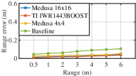
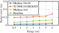
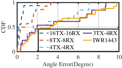
Ranging and AOA accuracy: We compare the ranging and AoA accuracy of the Medusa’s MIMO radar with the COTS UWB and mmWave radars 1. We use a reflector box and position it at various distances and angles, (but at the same height as the radar) and measure the range and AoA of the strongest reflected signal, and compare it with the ground truth. Fig.15 and Fig.17 show the ranging and AoA performance, respectively. Medusa’s MIMO radars, both the and configurations have errors < 7.55 cm and < 9.4 cm, respectively. The COTS UWB SISO radar’s range errors can go up to 16.2 cm in NLoS at 6m distance, and COTS MIMO mmWave radars due to their low penetration has NLoS errors of 0.3 m at 6m distance. Similarly, for AoA in LoS, measured at 5m distance, Medusa MIMO radars perform better than the COTS mmWave radar. Median angular errors for Medusa is only 2 deg and a max AoA error of 8.2 deg, while the COTS mmWave radar’s AoA median errors are 6.2 deg while max angular error can go up to 12.5 deg. Experimental results from range estimation and AoA reveal that a co-located MIMO array, equipped with a denser antenna configuration (), achieves a superior SNR gain. This setup outperforms the distributed MIMO sub-arrays in ranging and AoA. Further experiments on vital sign monitoring will showcase the benefits of spatial diversity gain in real-life environments.
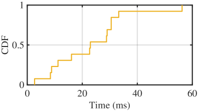
System Latency and Wireless Coherency: Fig.17 shows a median latency of 22.94ms for respiration waveform reconstruction, from the time radar data was received, proving that Medusa can indeed run in real-time.
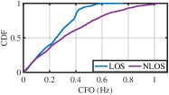
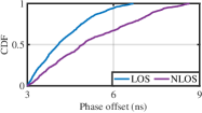
Next, we show the efficacy of Medusa’s of wireless clock synchronization in both LOS and NLOS conditions. As shown in Fig. 18(a), median carrier frequency offset (CFO) is 0.25Hz in LOS and 0.3Hz in NLOS. Fig. 18(b) displays the phase offset during the wireless synchronization of clock signals. The median offset is only 4ns in LOS and 4.9ns in NLOS.
4.2 Experiment Setup
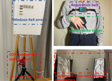
Ground truth (GT): For the GT, we use Vernier’s breathing belt [4] and heart rate sensor [2]. All the human participants in our evaluation wear these sensors during experiments. Necessary consent and IRB approvals were sought before all experiments. Fig 20 shows the overall experiment setup.
Baseline: In our assessment, we employ two baselines. For respiration pattern detection, we utilize prior work [44, 13] as a baseline. For heart pulse pattern detection, we compare Medusa with RFSCG [16], which is implemented on the TI mmWave radar IWR1443 [1].
Data Collection: We collect data at four different indoor locations (residential unit), using 27 different volunteers (14 men, 13 women) aged between 21-34 years (), weighing between 52-102 kg (), and heights varying from 164-187cm(). Volunteers during data collection dressed casually, and no one reported any cardiovascular problems. We collect data of each person performing the following actions: (1) static dataset: standing, sitting with their body oriented in different directions. (2)mobile dataset: Walking and jogging across a room in different directions, standing up and sitting down in continuous and staggered motion, jogging at the same spot with different body orientations, and performing various hand gestures. We collected 3.75TB of data to train the Medusa model, with 1.89TB for static subjects and 1.86TB for moving subjects. The datasets were divided into training and test sets at an 80:20 ratio, resulting in approximately 3.04TB for training and 710GB for testing. The model was trained using the training dataset and assessed with the test dataset.
4.3 Self-supervised HVM model
Medusa leverages a self-supervised learning model to recover human vital signals, and here we describe the network architecture and training process in detail.
Network structure: The self-supervised HVM model includes a classifier and an encoder with a multi-head attention layer, implemented using TensorFlow by Python 3.8. Binary cross-entropy is utilized as the classification loss. We added a multi-head attention layer before the Dense layer, assigning attention weights to each MIMO antenna array in the model design and the rationale behind this approach is that the multi-head attention mechanism can identify which parts of the input data are most significant, causing the system to focus more on influential antennas.
Training details: The model is trained on a PC featuring an AMD Ryzen 6900 CPU and an RTX 3080 Ti graphics card. Upon deploying the trained model, data is transmitted from the baseboard to the PC through a high-speed Ethernet interface. For a measurement duration of 2 minutes, the collected data has a size of 1.8GB and requires approximately 2 hours of model training using a single RTX 3080 Ti graphics card with 200 iterations. During training, datasets are split 80:20 for training and testing, using the leave-one-person-out cross-validation (LOPO CV) technique. The model is trained with the training dataset and evaluated with the test dataset, iteratively executed for each individual, ensuring each person’s data is used as the test dataset once. This process is carried out iteratively for each participant in the dataset, guaranteeing that each individual’s data is used as the test dataset precisely once. Our self-supervised contrastive learning model eliminates the need for labeled data and incurs a one-time training overhead. The model can adapt and effectively track vital signs in real-time even in un-seen environments and human subjects using spatially distributed MIMO antenna arrays, as discussed in Section 4.
4.4 Performance Evaluation:
4.4.1 Medusa: Accuracy and Robustness
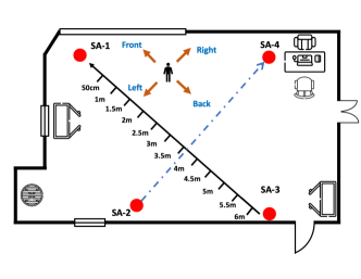
We begin evaluating Medusa’s robustness to monitor the Respiration-Per-Minute (RPM) of static and mobile users in LoS and NLoS when they are oriented in different directions. The experiment setup with the room layout, radar placement locations, items of furniture, as well as distances between radars are shown in Fig 19. The four subarray of Medusa is located at corners and we named them SA-1, SA-2, SA-3 and SA-4.
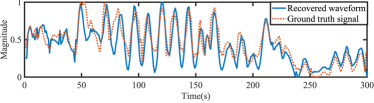
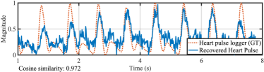
Waveform Recovery: Figure 23 displays the reconstructed waveform from Medusa for a randomly chosen participant positioned at 5 meters and facing left. The reconstructed waveform closely resembles the actual ground truth waveform, exhibiting a cosine similarity of 0.987. The recovered waveform for a random static target in NLoS is shown in Fig 23(b).
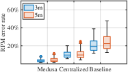
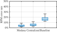
Static LoS: Fig 21 presents the box-plot of RPM accuracy for static users (measured individually) when they are either standing or sitting and facing two different directions (body orientations) at distances 3m and 5m distance. The RPM accuracy decreases at 5m for the co-located 16x16 radar facing frontward (refer to Fig 21), dropping by 12.1% when compared to the accuracy when facing left. The baseline’s performance is worse than the co-located 16x16 radar due to its poor SNR, especially when the user is 5m away, facing either front or left. Medusa, on the other hand, with MIMO distributed subarrays compensates for the drop in SNR (see Fig 20) when the target is 5m away by combining signals from the other three radars, providing an RPM improvement of 5.8% and 18.5% over the baseline and co-located deployments, respectively. The benefits of Medusa are seen further when the target is oriented to the left at the 5m mark. When the baseline and the co-located solutions suffer, Medusa still estimates the RPM with median errors <2.8%.
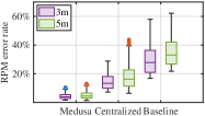
Static NLoS: To create NLoS conditions, we manually place the barrier screen (refer to Fig 20) in front of the back and right radars. Fig 22 shows the box-plot for RPM errors for all the individuals standing at the same 3m and 5m mark but oriented back and right (refer to Fig 19). When participants face the back array, Medusa’s median RPM errors are 3.6% at 3 meters and 4.4% at 5 meters. Meanwhile, when facing the right, the median RPM errors measured by Medusa are 4.6% at 3 meters and 4.9% at 5 meters, a gain of 17.5% and 25.9% over co-located and baseline solutions at 5 meters, respectively.
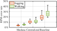
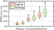
Mobility in LoS and NLoS: We next show the result for RPM estimation when targets are mobile in LoS and NLoS (2 covered radars) conditions. Fig 24 showed the box plot of the average RPM errors per target when walking and jogging in random directions in LoS and in NLoS. In LoS, Medusa’s measured RPM errors are 3.5% and 4.4% during walking and jogging, respectively, while in NLoS, Medusa’s measured median RPM errors are 4.6% and 6.3%, respectively. On the other hand, the co-located (16x16) single radar and the baseline solutions suffer, especially in NLoS conditions, with their respective median RPM errors increasing to 14.9% and 28%, respectively. Medusa delivers median gains of 10.3% and 21.7%, and max. gains of 21% and 38% over the co-located and baseline solutions, respectively.
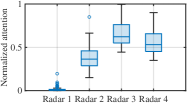
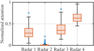
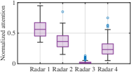
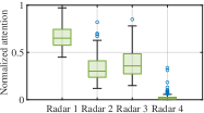
4.4.2 Impact on Attention-weights in NLoS.
We show how Medusa modifies attention weights for each radar depending on the received signal quality. In this experiment, we sequentially block one subarray (SA) at a time (SA-1 to SA-4) and measure the RPM of static targets at 3m. Fig 25 illustrates the normalized attention weight distribution when different SAs are blocked. Medusa reduces attention weights for radars with poor SNR (NLoS) and increases weights for radars with higher SNRs (LoS). Blocked SAs are given lower preference, focusing instead on radars with better-received signals.
4.4.3 Medusa in unknown environments
Next, we evaluate Medusa’s ability to generalize to different environments than where it was trained to ensure a true "in-the-wild" deployment. We train Medusa using data from a residence and use the model in a university lab.
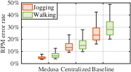
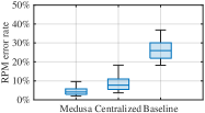
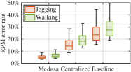
Targets in LoS: We perform static and mobility experiments with various targets in the radars’ LoS. In the static experiment, targets stand anywhere in the room, in any orientation. In the mobility experiment, targets continuously walk and jog within the room. Fig 26 displays RPM errors for static and mobile experiments. Medusa’s median RPM errors are 3.7% for static targets and 4.6% and 6.1% for jogging and walking, respectively. Medusa outperforms the co-located and baseline solutions with accuracy gains of 14.2% and 27%, respectively.
Targets in NLoS: We evaluate RPM errors for static and mobile targets in NLoS conditions, as shown in Fig 27. With two blocked radars, co-located and baseline solutions’ median errors shoot up to 8.7% and 25.9% for static targets, with max errors of 18.3% and 38%, respectively, while Medusa’s median error is 4.1%, improving median accuracy by 4.6% and 21.8% over the other solutions. For mobile targets, Medusa accuracy gains are 10.4% and 19.2% for jogging and 12.3% and 21.4% for walking, over the co-located and baseline solutions, respectively.
4.4.4 Case of Multiple Targets
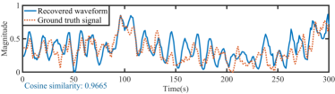
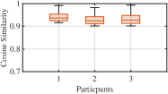
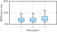
With multiple targets inside a room, Medusa can extract each individual’s respiration waveforms by decomposing the composite RF signals. However, it cannot map these extracted waveforms to individual targets. Mapping the recovered individual waveforms to specific targets requires continuous localization and tracking of each target, which we leave as future work. Nonetheless, we show Medusa’s ability to recover the individual respiration waveforms and to accurately measure the individual RPM by manually associating the recovered waveform to the target. Fig 28 shows the cosine similarity of the recovered waveforms for three mobile targets in a room and their RPM accuracy. Median cosine similarity for the three waveforms are 0.923, 0.934, and 0.9216, respectively, and median RPM errors are 4.5%, 4.7%, and 5.5%.
4.4.5 Measuring Heart Rate
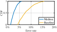
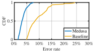
Lastly, we showcase Medusa’s ability to measure an individual’s heart rate passively. To effectively capture chest vibrations caused by heartbeats, targets must be close to the radar (e.g., 50cm, 1m). In RFSCG [16], researchers measured heart rate using COTS mmWave TI radar, which we use as a baseline for comparison. Fig 30 presents the CDF of heart rate estimation errors for various MIMO radar configurations and targets. At 50cm distance, Medusa clearly offers the most accurate estimation, reducing errors by 7.4% in median cases and 24% for the 90th percentile, significantly surpassing the baseline solution.
5 Conclusion
In summary, Medusa presents a groundbreaking 256-element virtual MIMO radar system that facilitates robust and precise distributed radar sensing across diverse target-environment configurations. Our comprehensive experiments demonstrate that Medusa significantly outperforms existing solutions in terms of vital measurement accuracy for both stationary and moving targets. Medusa lays the foundation for a feasible, contact-free vital monitoring solution that can be effectively implemented at scale in real-world settings.
References
- [1] IWR1443. https://www.ti.com/tool/IWR1443BOOST/.
- [2] Neulog Heart Pulses Logger. https://neulog.com/heart-rate-pulse/.
- [3] Novelda XeThru X4. https://novelda.com/.
- [4] Respiration Belt. https://www.vernier.com/product/go-direct-respiration-belt/.
- [5] Xilinx Zynq UltraScale+ MPSoC XCZU4EV. https://www.xilinx.com/products/silicon-devices/soc/zynq-ultrascale-mpsoc.html.
- [6] O. Abari, H. Rahul, D. Katabi, and M. Pant. AirShare: Distributed coherent transmission made seamless. In Proc. of the 34th IEEE INFOCOM, pages 1742–1750, 2015.
- [7] F. Adib, H. Mao, Z. Kabelac, D. Katabi, and R. C. Miller. Smart homes that monitor breathing and heart rate. In Proceedings of the 33rd Annual ACM Conference on Human Factors in Computing Systems, CHI ’15, page 837–846, New York, NY, USA, 2015. Association for Computing Machinery.
- [8] F. Adib, H. Mao, Z. Kabelac, D. Katabi, and R. C. Miller. Smart homes that monitor breathing and heart rate. In Proceedings of the 33rd Annual ACM Conference on Human Factors in Computing Systems, CHI ’15, page 837–846, New York, NY, USA, 2015. Association for Computing Machinery.
- [9] K. Alemdar, D. Varshney, S. Mohanti, U. Muncuk, and K. Chowdhury. RFClock: Timing, Phase and Frequency Synchronization for Distributed Wireless Networks. In Proc. of the 27th ACM MobiCom, MobiCom ’21, page 15–27, 2021.
- [10] E. Biglieri, R. Calderbank, A. Constantinides, A. Goldsmith, A. Paulraj, and H. V. Poor. MIMO wireless communications. Cambridge university press, 2007.
- [11] F. A. Butt, M. A. Aslam, M. T. Zafar, I. H. Naqvi, and U. Riaz. Synchronization of Long-Range, Widely-Separated MIMO Radar Network using GSM Protocol. In 2018 19th International Radar Symposium (IRS), pages 1–10, 2018.
- [12] W. Chen and D. McDuff. Deepphys: Video-based physiological measurement using convolutional attention networks. CoRR, abs/1805.07888, 2018.
- [13] Z. Chen, T. Zheng, C. Cai, and J. Luo. Movi-fi: Motion-robust vital signs waveform recovery via deep interpreted rf sensing. In Proceedings of the 27th Annual International Conference on Mobile Computing and Networking, MobiCom ’21, page 392–405, New York, NY, USA, 2021. Association for Computing Machinery.
- [14] Z. Chen, T. Zheng, and J. Luo. Octopus: A practical and versatile wideband mimo sensing platform. MobiCom ’21, page 601–614, New York, NY, USA, 2021. Association for Computing Machinery.
- [15] J. Gong, X. Zhang, K. Lin, J. Ren, Y. Zhang, and W. Qiu. RF Vital Sign Sensing under Free Body Movement. Proc. ACM Interact. Mob. Wearable Ubiquitous Technol., 5(3), sep 2021.
- [16] U. Ha, S. Assana, and F. Adib. Contactless seismocardiography via deep learning radars. In Proceedings of the 26th Annual International Conference on Mobile Computing and Networking, pages 1–14, 2020.
- [17] A. Hyvärinen and H. Morioka. Unsupervised feature extraction by time-contrastive learning and nonlinear ica. In Proceedings of the 30th International Conference on Neural Information Processing Systems, NIPS’16, page 3772–3780, Red Hook, NY, USA, 2016. Curran Associates Inc.
- [18] O. J. Kaltiokallio, H. Yigitler, R. Jäntti, and N. Patwari. Non-invasive respiration rate monitoring using a single cots tx-rx pair. In Proceedings of the 13th International Symposium on Information Processing in Sensor Networks, IPSN ’14, page 59–70. IEEE Press, 2014.
- [19] C. Li and J. Lin. Random body movement cancellation in doppler radar vital sign detection. IEEE Transactions on Microwave Theory and Techniques, (12):3143–3152, 2008.
- [20] J. Liu, Y. Wang, Y. Chen, J. Yang, X. Chen, and J. Cheng. Tracking vital signs during sleep leveraging off-the-shelf wifi. In Proceedings of the 16th ACM International Symposium on Mobile Ad Hoc Networking and Computing, MobiHoc ’15, page 267–276, New York, NY, USA, 2015. Association for Computing Machinery.
- [21] D. Makowski, T. Pham, Z. J. Lau, J. C. Brammer, F. Lespinasse, H. Pham, C. Schölzel, and S. H. A. Chen. NeuroKit2: A python toolbox for neurophysiological signal processing. Behavior Research Methods, 53(4):1689–1696, feb 2021.
- [22] J.-M. Muñoz-Ferreras, Z. Peng, R. Gómez-García, and C. Li. Random body movement mitigation for fmcw-radar-based vital-sign monitoring. In 2016 IEEE Topical Conference on Biomedical Wireless Technologies, Networks, and Sensing Systems (BioWireleSS), pages 22–24, 2016.
- [23] P. Nguyen, X. Zhang, A. Halbower, and T. Vu. Continuous and fine-grained breathing volume monitoring from afar using wireless signals. In IEEE INFOCOM 2016 - The 35th Annual IEEE International Conference on Computer Communications, pages 1–9, 2016.
- [24] J. Ni, F. Zhang, J. Xiong, Q. Huang, Z. Chang, J. Ma, B. Xie, P. Wang, G. Bian, X. Li, and C. Liu. Experience: Pushing indoor localization from laboratory to the wild. In Proceedings of the 28th Annual International Conference on Mobile Computing And Networking, MobiCom ’22, page 147–157, New York, NY, USA, 2022. Association for Computing Machinery.
- [25] A. Pai, A. Veeraraghavan, and A. Sabharwal. Hrvcam: robust camera-based measurement of heart rate variability. Journal of Biomedical Optics, 26, 02 2021.
- [26] T. Pham, Z. J. Lau, S. H. A. Chen, and D. Makowski. Heart rate variability in psychology: A review of hrv indices and an analysis tutorial. Sensors, 21(12), 2021.
- [27] S. Prager, M. S. Haynes, and M. Moghaddam. Wireless Subnanosecond RF Synchronization for Distributed Ultrawideband Software-Defined Radar Networks. IEEE Transactions on Microwave Theory and Techniques, 68(11):4787–4804, 2020.
- [28] X. Song, B. Yang, G. Yang, R. Chen, E. Forno, W. Chen, and W. Gao. Spirosonic: Monitoring human lung function via acoustic sensing on commodity smartphones. In Proceedings of the 26th Annual International Conference on Mobile Computing and Networking, MobiCom ’20, New York, NY, USA, 2020. Association for Computing Machinery.
- [29] M.-C. Tang, F.-K. Wang, and T.-S. Horng. Single self-injection-locked radar with two antennas for monitoring vital signs with large body movement cancellation. IEEE Transactions on Microwave Theory and Techniques, 65(12):5324–5333, 2017.
- [30] A. Vaswani, N. Shazeer, N. Parmar, J. Uszkoreit, L. Jones, A. N. Gomez, L. u. Kaiser, and I. Polosukhin. Attention is all you need. In I. Guyon, U. V. Luxburg, S. Bengio, H. Wallach, R. Fergus, S. Vishwanathan, and R. Garnett, editors, Advances in Neural Information Processing Systems, volume 30. Curran Associates, Inc., 2017.
- [31] A. Wang, J. E. Sunshine, and S. Gollakota. Contactless infant monitoring using white noise. In The 25th Annual International Conference on Mobile Computing and Networking, MobiCom ’19, New York, NY, USA, 2019. Association for Computing Machinery.
- [32] F.-K. Wang, T.-S. Horng, K.-C. Peng, J.-K. Jau, J.-Y. Li, and C.-C. Chen. Single-antenna doppler radars using self and mutual injection locking for vital sign detection with random body movement cancellation. IEEE Transactions on Microwave Theory and Techniques, 59(12):3577–3587, 2011.
- [33] T. Wang, D. Zhang, Y. Zheng, T. Gu, X. Zhou, and B. Dorizzi. C-fmcw based contactless respiration detection using acoustic signal. Proc. ACM Interact. Mob. Wearable Ubiquitous Technol., 1(4), jan 2018.
- [34] X. Xu, J. Yu, Y. Chen, Y. Zhu, L. Kong, and M. Li. Breathlistener: Fine-grained breathing monitoring in driving environments utilizing acoustic signals. In Proceedings of the 17th Annual International Conference on Mobile Systems, Applications, and Services, MobiSys ’19, page 54–66, New York, NY, USA, 2019. Association for Computing Machinery.
- [35] Z. Yang, P. H. Pathak, Y. Zeng, X. Liran, and P. Mohapatra. Vital sign and sleep monitoring using millimeter wave. ACM Trans. Sen. Netw., 13(2), apr 2017.
- [36] Z. Yu, W. Peng, X. Li, X. Hong, and G. Zhao. Remote heart rate measurement from highly compressed facial videos: an end-to-end deep learning solution with video enhancement, 2019.
- [37] S. Yue, H. He, H. Wang, H. Rahul, and D. Katabi. Extracting Multi-Person Respiration from Entangled RF Signals. Proc. ACM Interact. Mob. Wearable Ubiquitous Technol., jul 2018.
- [38] S. Yue, H. He, H. Wang, H. Rahul, and D. Katabi. Extracting multi-person respiration from entangled rf signals. Proc. ACM Interact. Mob. Wearable Ubiquitous Technol., 2(2), jul 2018.
- [39] Y. Zeng, D. Wu, R. Gao, T. Gu, and D. Zhang. Fullbreathe: Full human respiration detection exploiting complementarity of csi phase and amplitude of wifi signals. Proc. ACM Interact. Mob. Wearable Ubiquitous Technol., 2(3), sep 2018.
- [40] Y. Zeng, D. Wu, J. Xiong, E. Yi, R. Gao, and D. Zhang. Farsense: Pushing the range limit of wifi-based respiration sensing with csi ratio of two antennas. 3(3), sep 2019.
- [41] F. Zhang, J. Xiong, Z. Chang, J. Ma, and D. Zhang. Mobi2sense: Empowering wireless sensing with mobility. MobiCom ’22, New York, NY, USA, 2022. Association for Computing Machinery.
- [42] S. Zhang, T. Zheng, Z. Chen, and J. Luo. Can we obtain fine-grained heartbeat waveform via contact-free rf-sensing? In IEEE INFOCOM 2022 - IEEE Conference on Computer Communications, pages 1759–1768, 2022.
- [43] T. Zheng, Z. Chen, C. Cai, J. Luo, and X. Zhang. V2ifi: In-vehicle vital sign monitoring via compact rf sensing. 4(2), jun 2020.
- [44] T. Zheng, Z. Chen, S. Zhang, C. Cai, and J. Luo. More-fi: Motion-robust and fine-grained respiration monitoring via deep-learning uwb radar. In Proceedings of the 19th ACM Conference on Embedded Networked Sensor Systems, SenSys ’21, page 111–124, 2021.