Soft finger dynamic stability and slip by Coulomb friction and bulk stiffness
Abstract
Soft robotic fingers can safely grasp fragile or non-uniform objects, but their force capacity is limited, especially with less contact area: objects which are smaller, not round, or where an enclosing grasp is not feasible. To improve force capacity, this paper considers two types of grip failure, slip and dynamic rotational stability. For slip, a Coulomb model for soft fingers based on total normal and tangential force is validated, identifying the effect of contact area, pressure, and grip position on effective Coulomb coefficient, normal force and transverse stiffness. For rotational stability, bulk stiffness of the fingers is used to develop conditions for dynamic stability about the initial grasp, and a condition for when the rotation leads to slip. Together, these models suggest contact area improves grip by increasing transverse stiffness and normal force. The models are validated in a range of grasp conditions, shown to predict the influence of object radius and finger distance on grip stability limits.
1 Introduction
Soft fingers aim to improve generalization of grasping and manipulation, especially with objects which are sensitive or have variation in surface geometry. Soft fingers have been shown to grasp a large range of objects, especially spherical or cylindrical objects when an enclosing grasp is used [1, 2]. Such applications are well-suited to pick-and-place tasks in unobstructed environments [3], where a large contact area between finger and object can be employed.
However, soft fingers typically have reduced force transmission capacity compared with rigid fingers [4]. The soft materials have limited ability to build normal force at the contact surface [5], and compliance in the normal direction makes force closure effects more complex [6]. This force transmission limitation can be even more significant when contact area is reduced; when smaller or flat objects are grasped, or when cluttered environments limit the ability to realize large contact areas [3].
[width=0.3]svg-inkscape/intro_1_svg-tex.pdf_tex
[width=0.55]svg-inkscape/intro_2_svg-tex.pdf_tex
This can be a limitation in both the ability to manipulate heavy objects [7] and in moving from pick-and-place to contact-rich manipulation, which often requires more force [8]. Ongoing work has explored increasing force capacity using stiffening elements [9], jamming techniques to increase stiffness [10], incompressible actuating fluids [7], additional kinematic structure to increase contact area [11], and structured compliance which is stiffer where forces are needed [12]. The force capacity is also affected by grip parameters such as degree of actuation, robot grip pose, and finger distance. However, the optimal grip parameters are highly object specific. To determine good grip parameters for a specific object, deep learning approaches are common for grasp pose planning [13], but not yet applied to optimizing force capacity in soft grasps.
Soft finger force capacity is limited by at least two phenomena, slip and stability. Grip stability has a wide range of definitions [14, 15]. Planar grip stability has been studied for force-closure [16], form-closure [17], and stiff-but-underactuated fingers [18]. However, these analyses assume point contact between object and gripper, as well as the gripper contact point being perfectly stiff, allowing the expression of a static grip matrix which forms the basis of most further analysis [14]. These analyses cannot be directly applied to soft fingers, where contact is neither point-like and the contact patches move in response to force. Some approaches do model finger compliance [15], such as for tendon-driven fingers [19] or spherical fingertips [6], considering Coulomb force conditions with linear stiffness models. However, dynamic instability can be observed in soft fingers, where rotation away from an initial object orientation occurs, as seen in Figure 1. This effect is not initiated by slip, and requires modeling motion transverse to the grip normal.
Slip is typically modelled with Coulomb friction in grasping [14, 20]. However, a Coulomb friction model is a point-contact model, raising questions about its applicability when the contact area is larger. Finite-element based contact models are being developed [21, 22], but not yet applied to grip slip or stability. For spherical soft fingers, closed-form friction models which include a torsional friction about the contact normal have been proposed [23, 24, 6], but not extended to general soft fingers. Deep-learning approaches for slip detection or prediction [20] have been used for trajectory planning [25], but not finger design or optimization of grip parameters.
To increase the force capacity of soft fingers, this paper proposes a model for dynamic stability and validates the bulk Coulomb model. Compared with friction modelling in soft fingers [20, 24], we examine the effect of contact area, pressure, and offset, finding their impact on effective Coulomb coefficient. This suggests increasing normal force is the primary way to increase force capacity. However, we find that dynamic instability occurs as grip force increases. This is then modelled, considering bulk finger stiffness, developing dynamic stability conditions which depend on grip force, transverse stiffness, and object radius. Compared with classical grip stability [14, 16, 17, 18, 19], this is the dynamic stability of a compliant system, analyzing the convergence to a certain pose. This paper first validates the Coulomb model for pneumatic fingers, finding the influence of contact area on finger slip force. Next, a model for dynamic rotational stability is proposed, and conditions for this rotation to cause slip developed. These models are validated experimentally on a range of object sizes and grip conditions, validating the effect of object radius, contact area and finger stiffness on maximum stable grip force.
2 Friction modelling
This section introduces the friction model, validating the bulk Coulomb model for soft fingers. Coulomb friction models slip as a violation of the condition , where is the Coulomb friction coefficient, normal force and tangential force. These models are popular, even in soft robotics [26, 9, 27]. They can also be made stochastic, where can be considered to vary with a distribution [20].
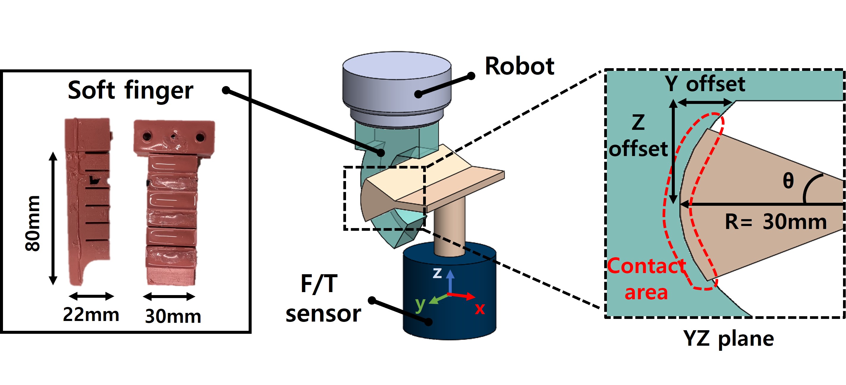
However, the Coulomb model is a point model, and it is unclear how it applies to larger contact areas. One reason for this is that the pressure distribution over the contact area not uniform, which can result in local slip, where local relative motion occurs before bulk slip [23]. Computational methods to estimate contact pressure have been proposed [22], but not yet extended with frictional models. An additional effect on larger contact areas is torsional friction, which can be modelled on spherical geometries [24], but not yet extended to general contact. To investigate the accuracy of the bulk Coulomb friction over soft grasp parameters (contact area, offset, pressure, material), we develop a test environment as seen in Figure 2.
2.1 Validation of bulk Coulomb
The experimental setup seen in Figure 2 is used with test objects 3D printed from Tough PLA which are sections of a cylinder of radius mm. In this way, the contact area is controlled by the test object, provided the finger is in contact with the full arc of the object, which is verified visually per experiment. The test objects are mounted onto a Force/Torque sensor (ME-Meßsysteme MP11, load limit 500N, 20Nm, sampling rate 125Hz) to allow measurement of the total normal and transverse force.
Pneumatic fingers are made with Wacker RT625 Elastosil, and the kinematic structure is an adjusted form of the Pneunet fingers [28]. They are actuated by controlled pressure valves (VEAB-L-26-D9-Q4-V1-1R1, Festo), where a constant desired pressure is applied and real pressure measured. The fingers are mounted on a Universal Robots UR10, which is used to initiate contact and load the fingers. We then compare five different parameters: pressure, contact area, relative position between finger and contact object (horizontal and vertical offset) and contact surface material. The range of parameters tested is shown in Table 1. The high friction condition applies a rubber to the surface of the test object.
For each set of parameters, the following experiment process is followed: (i) the finger is actuated in free space, (ii) the robot moves the finger into contact, (iii) contact along the entire test object is visually verified, (iv) linear motion in the positive y direction begins, with a velocity of mm/s and to a distance of mm, (v) the robot moves back to the initial pose. As the robot moves in the y direction, the total transverse force, which is friction force, can be directly measured as from the force/torque sensor. The total normal force is calculated as , where is assumed to be from asymmetrical contact pressure, not friction, as the contact has been established with motion in x. The ratio of friction force to the total normal force is plotted, which saturates at during slip. Experiments are conducted for each parameter combination three times, and the graph displays the mean value.
| Parameter name | Value |
| Pressure [] | 0.4, 0.8, 1.2 |
| Contact area [] | 2.1(S), 4.2(M), 8.4(L) |
| Horizontal offset [] | 0, -10, -20 |
| Vertical offset [] | 40, 60, 80 |
| Contact surface material friction | Ordinary, High |
[width=0.48]svg-inkscape/14Sept_pressure_G_svg-tex.pdf_tex
[width=0.48]svg-inkscape/14Sept_CA_G_svg-tex.pdf_tex
[width=0.48]svg-inkscape/14Sept_HOR_G_svg-tex.pdf_tex
[width=0.48]svg-inkscape/14Sept_VER_G_svg-tex.pdf_tex
[width=0.48]svg-inkscape/14Sept_Fric_pressure_G_svg-tex.pdf_tex
[width=0.48]svg-inkscape/14Sept_FRIC_CA_G_svg-tex.pdf_tex
[width=0.48]svg-inkscape/14Sept_off_H_G_svg-tex.pdf_tex
[width=0.48]svg-inkscape/14Sept_off_V_G_svg-tex.pdf_tex
[width=0.46]svg-inkscape/14Sept_Fc_1_G_svg-tex.pdf_tex
[width=0.46]svg-inkscape/14Sept_Fc_2_G_svg-tex.pdf_tex
In all of the results for friction force in Figure 3 and ratio of friction to normal force in Figure 5, three phases can be identified: the stick phase, where the fingertip is not moving while the robot moves with constant velocity, a transition region, and a constant friction phase as sliding occurs. The slope in the stick phase represents the soft finger’s bulk stiffness in y, , as it stretches horizontally.
Increased pressure leads to higher normal forces, as seen in Figure 3(a), but does not affect stiffness in the direction of motion. Similarly, contact area changes the normal force significantly, but has negligible impact on in Figure 5(a). However, contact area does increase this stiffness. Neither of these parameters affects as much as material, shown in gray in 5(a). On the other hand, variation in the robot’s horizontal and vertical position cause larger changes in , as seen in Figure 5(b), possibly due to the different contact pressure distributions. Additionally, a higher vertical offset increases the transverse stiffness as seen in the stick phase of Figure 4, as the object is closer to the finger basis.
The results are summarized in Table 2, showing the effects of a unit change of each parameter on and and the range of realized. These results suggests that normal force and material are more important than contact area and pressure for the friction force limits. Variation in the grip pose can change the normal pressure distribution, which can cause larger variation in . Stiffness in the direction of motion is mostly affected by vertical offset and contact area.
| Parameter | [N/unit] | [N/(mm unit)] | (std) |
| Pressure | 0.58 () | ||
| Contact area | 0.63 () | ||
| Horizontal offset | 0.62 () | ||
| Vertical offset | 0.72 () |
3 Dynamic grip stability
If a bulk Coulomb model with a constant is accurate, increasing force capacity should be as easy as increasing normal force . However, in some cases this leads to rotation of the object, in either yawing or rolling as seen in 1(a), which can lead to slip as seen in Figure 1(b).
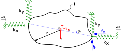
To understand why this happens, we define dynamic grip stability as the convergence of the object rotation to the initial rotation angle over time. To evaluate the dynamic stability, the model in Figure 6 is used. We model the object’s pose relative to the robot flange with stiffnesses, where one side is fixed to the flange and the other to the object. We assume that the stiffnesses are linear and equal between the fingers, ignore any torsional stiffness at the contact area, and assume that the direction of the normal and transverse force stays constant. We derive a dynamics equation and analyze the stability about the equilibrium point using the eigenvalues, where only a rotational motion of the body with the torsion angle is studied.
Let the bulk stiffness of the fingers be modeled with the corresponding stiffness in the normal force direction and in transversal direction, with a radius to the center of mass of the object. Grip force of finger in x direction is modeled by the spring with a relative spring displacement and preload in the y direction is assumed to be .
3.1 Rotational dynamics
We model the pure rotation of the object seen in Figure 6. The dynamics can be determined based on the energies of the system with Lagrangian mechanics
| (1) |
where . The total kinetic energy of the system in the case of a pure rotation is given by
| (2) |
where is the rotational inertia and the rotation speed about . The potential energy of the system is derived from the relative travel of the spring through the preload and through the distance covered by the springs during object rotation. As the body rotates, the spring displacement changes, giving the potential energy
| (3) |
where is object radius, and the stiffness in respective directions, and the preload displacement. With (2) and (3) inserted into (1) the dynamic equation can be calculated to
| (4) |
3.2 Linearized dynamics and stability
With defining of the state vector , the problem can be considered from the control systems point of view. The system is nonlinear, but the linearized dynamics can be found and dynamic stability about can be analyzed. When the system is dynamically stable about a state, it converges to that state over time from starting conditions near that state. When the system is dynamically unstable, it will diverge.
With the introduced state variables, the system matrix linearized about the equilibrium point can be written as
| (5) |
where about . The matrix has two eigenvalues which can be found as
| (6) |
If the term exerted by the finger, is greater than the stiffness in the transverse direction times the distance to the center of masses , then there will be a pole located in the right half-plane, indicating instability. This gives a dynamic stability condition about the equilibrium point of
| (7) |
and we denote the force when this condition is violated as . As seen in Figure 1, instability can also happen about the x axis, in this case the model results in the condition .
3.3 Rest position
The derived dynamic equation (4) can be used to predict the angle that occurs after the force is applied by the fingers by setting to zero, which has solutions for for , and additional solutions at when
| (8) |
The progression of the rest position angle over the applied force is shown for selected system parameters in the Figure 7. It can be seen that the object rotates when a certain limit force is exceeded, where this limit force follows from (7). It should be noted that if the condition (8) for the analytical solution is not satisfied, the progression of the rest position angle cannot be calculated and only the force can be determined.
The comparison of these results for different and values can be seen in Figure 8. As indicated by (7), the initiation of rotation depends on , increasing as increases. However, the slope after rotation is initiated decreases as increases.
[width=0.85]svg-inkscape/theta_svg-tex.pdf_tex
[width=0.8]svg-inkscape/kxky_svg-tex.pdf_tex
3.4 Rotation leading to slip
As the object rotates, the normal and transverse forces change, possibly leading to slip. The Figure 6 shows the normal force and static friction force , which from the nonlinear model can be defined as follows:
| (9) | |||||
| (10) | |||||
| (11) |
where is the preload force on the finger. These equations are connected by the Coulomb friction condition . With the assumption that the direction of the forces and doesn’t change with rotation, the limiting case for the angle from which the slip begins can be determined by solving , which gives [29]
| (12) |
where and . The angle indicates the rotation at which slip occurs. This can be calculated for the same set of parameters and is also plotted in the Figure 7. It follows that slip does not occur if the rest position of the system remains smaller than the critical angle for the friction condition .
4 Experimental validation of grip stability model
To validate the model with stability conditions, silicon-based fingers are used in a variety of conditions. The model in Section 3 makes two predictions: when rotation away from initial orientation begins , and when the rotation leads to slip at . For some grip conditions, these two are close - when the slope of over is high. In other cases, increases slowly.
4.1 Experimental set up
The first goal is to test the stability condition (7) about the equilibrium point when grasping an object. The assumptions in the derivation were that the distance between the fingers and the object center does not change and the fingers have the same properties, i.e. the stiffnesses , , are matched in both fingers. Furthermore, it is assumed that the stiffness of the fingers in the transverse direction does not change with changing in pressure, as indicated in Section 2.
The model predicts that if the force applied by the fingers is less than the term , then the object will remain in its initial rest position . If this limit force is exceeded, the rotation of the body should happen, similar to the Figure 7 and a new rest position should be assumed. As pressure increases, the slip force will be exceeded which often results in smaller objects flying from the fingers.
The stiffness of the finger is needed to validate the stability model. In order to calculate this, the test object is fixed on the force sensor and with the measuring force and displacement of robot’s end-effector, the stiffness of finger can be determined. First, the grip conditions from the stability experiment are recreated - relative pose between object and gripper, an the pressure in the finger. The end-effector is moved from to , the forces measured at each one as and , and the stiffness can be calculated with a simple relationship . To measure the stiffness in the y- and z- direction, a Cartesian motion of mm is used to avoid slip and stay in the linear range.
4.2 Force instability experiments
In each set of experiments, the object is grasped from an experiment table, with an initial grasp location flush with the bottom of the fingers. The pressure is increased in steps of around bar, waiting for seconds and stopping the experiment when instability and slip has occurred.
4.2.1 Validation of force stability limit
With the friction coefficient determined from the Section 2 and the calculated stiffnesses from the description above, the determined and observed values can be summarized in Table 3. The object and experimental setup can be seen in Figure 1(a).
| Parameter | Value |
| Stiffness | 0.14 |
| Stiffness | 0.11 |
| Stiffness | 0.05 |
| Object radius | 15 |
| Expected instability preload force about z | 1.65 |
| Expected instability preload force about x | 0.75 |
| Observed slip force about x | 1.5 |
To avoid rotation, the finger normal force should not exceed for instability about z, and not greater than for instability about x. In the experiments, the rotation about x was observed at force . And this also should be expected from the model, since the force limit about x is smaller than about z.
4.2.2 Finger distance and force limit
The effective finger stiffness is varied by varying the finger distance via an electrical parallel gripper, i.e. the offset between the finger and the body at each measurement, which influences the stiffnesses and preload force. A test object with a length of mm is grasped.
Table 4 shows a comparison of the derived model and the measured values of slip force about x at the different distance between the fingers. Furthermore, the expected instability force and is written in the table at which the rotation should begin, about the x and z axis, respectively.
| [mm] | [N] | [N] | [N] | [N/mm] |
| 50 | 1.5 | 1.65 | 0.75 | 0.14, 0.11, 0.05 |
| 40 | 2.15 | 1.2 | 1.05 | 0.11, 0.08, 0.07 |
| 30 | 2.9 | 1.2 | 6 | 0.1, 0.08, 0.4 |
| 20 | 3.38 | 1.2 | 9.3 | 0.1, 0.08, 0.62 |
[width=0.8]svg-inkscape/val_2_svg-tex.pdf_tex
It can be seen that when the stiffness in z is increased, the force that leads to dynamic instability and thus to slip of object increases, as predicted by the model. While the trend is correct, at higher values, the observed maximum force is lower than the model prediction. We attribute this to the non-negligible in realistic gripping scenarios, which gives additional transverse forces which can violate the slip condition earlier.
4.2.3 Changes in object properties
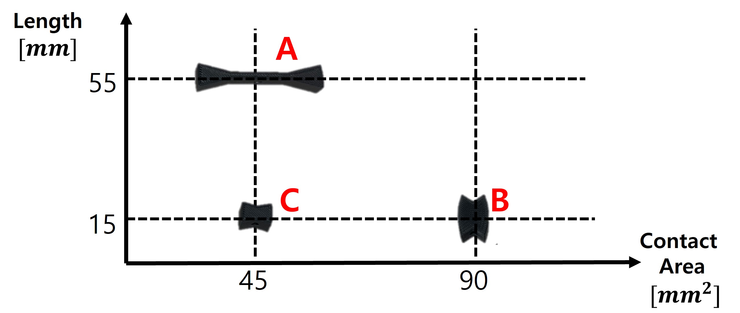
The grip stability limits are next assessed over a range of objects with different lengths and contact areas. The objects and the resulting observed slip force can be seen in Figure 9(a) and (b), respectively.
We can see that the object with a larger results in a higher , as predicted by the instability model. Additionally, the object with the larger contact area allows a higher grasp force. The larger contact area was shown to increase in Table 2, which would result in a higher instability force .
4.3 Rest angle validation
[width=0.75]svg-inkscape/theta1_svg-tex.pdf_tex
To validate the rest angle that the object takes as grip force is increased, we grasp a test object as seen in Figure 2(a) of length mm. A long indicating stick is glued to the bottom, and the object is lightly lifted off the table and the finger pressure is increased. As the pressure increases, the robot’s last axis is jogged back to align the indicator, providing a measurement of the rotation angle. The results can be seen in Figure 10, where the measured rest angle can be seen. While the initiation of rotation at the instability force matches the model prediction well, the resulting angles of the object are lower than predicted by the model by at least a factor of . We attribute this to the linearity assumptions of the finger stiffness, where additional displacement of the fingers may change the stiffness properties.
5 Conclusion
This paper investigated models to increase the friction force capacity of soft fingers. It was shown that with a bulk Coulomb model, increasing contact area mostly increases normal force and transverse stiffness, where coefficient is mostly unchanged. The normal force was then shown to have a rotational stability limit, where above a threshold grip force , rotation away from initial grasp point occurs. The instability model was validated for a range of grip parameters and objects, showing increasing object radius and transverse stiffness increase the stable normal force limit.
While the trends in object radius and bulk finger stiffness are validated, the observed instability force is lower than anticipated at higher stiffness values. Future work can apply more complex finger models which more accurately describe the gripping force direction and nonlinear stiffnesses.
References
- [1] R. Ozawa and K. Tahara, “Grasp and dexterous manipulation of multi-fingered robotic hands: A review from a control view point,” Advanced Robotics, vol. 31, no. 19-20, pp. 1030–1050, 2017.
- [2] J. Hernandez, M. S. H. Sunny, J. Sanjuan, I. Rulik, M. I. I. Zarif, S. I. Ahamed, H. U. Ahmed, and M. H. Rahman, “Current Designs of Robotic Arm Grippers: A Comprehensive Systematic Review,” Robotics, vol. 12, no. 1, p. 5, Jan. 2023.
- [3] C. Piazza, G. Grioli, M. Catalano, and A. Bicchi, “A Century of Robotic Hands,” Annual Review of Control, Robotics, and Autonomous Systems, vol. 2, no. 1, pp. 1–32, May 2019.
- [4] M. Li, A. Pal, A. Aghakhani, A. Pena-Francesch, and M. Sitti, “Soft actuators for real-world applications,” Nature Reviews Materials, vol. 7, no. 3, pp. 235–249, Nov. 2021.
- [5] S. Liu, F. Wang, Z. Liu, W. Zhang, Y. Tian, and D. Zhang, “A Two-Finger Soft-Robotic Gripper With Enveloping and Pinching Grasping Modes,” IEEE/ASME Transactions on Mechatronics, vol. 26, no. 1, pp. 146–155, Feb. 2021.
- [6] H. Dong, C. Qiu, D. K. Prasad, Y. Pan, J. Dai, and I.-M. Chen, “Enabling grasp action: Generalized quality evaluation of grasp stability via contact stiffness from contact mechanics insight,” Mechanism and Machine Theory, vol. 134, pp. 625–644, 2019.
- [7] O. Azami, K. Ishibashi, M. Komagata, and K. Yamamoto, “Development of hydraulically-driven soft hand for handling heavy vegetables and its experimental evaluation,” in 2023 IEEE International Conference on Robotics and Automation (ICRA). IEEE, 2023, pp. 2577–2583.
- [8] A. Billard and D. Kragic, “Trends and challenges in robot manipulation,” Science, vol. 364, no. 6446, p. eaat8414, Jun. 2019.
- [9] W. Park, S. Seo, J. Oh, and J. Bae, “A sensorized hybrid gripper to evaluate a grasping quality based on a largest minimum wrench,” IEEE Robotics and Automation Letters, vol. 5, no. 2, pp. 3243–3250, 2020.
- [10] K. Singh, S. Gupta, A. Khosla, and H. Furukawa, “Transforming Soft Robotics: Laminar Jammers Unlocking Adaptive Stiffness Potential in Pneunet Actuators,” ECS Journal of Solid State Science and Technology, vol. 12, no. 4, p. 047007, 2023.
- [11] J. Zhou, S. Chen, and Z. Wang, “A Soft-Robotic Gripper With Enhanced Object Adaptation and Grasping Reliability,” IEEE Robotics and Automation Letters, vol. 2, no. 4, pp. 2287–2293, Oct. 2017.
- [12] R. M. Hartisch and K. Haninger, “Compliant finray-effect gripper for high-speed robotic assembly of electrical components,” arXiv preprint arXiv:2301.08431, 2023.
- [13] R. Newbury, M. Gu, L. Chumbley, A. Mousavian, C. Eppner, J. Leitner, J. Bohg, A. Morales, T. Asfour, D. Kragic, D. Fox, and A. Cosgun, “Deep Learning Approaches to Grasp Synthesis: A Review,” IEEE Transactions on Robotics, pp. 1–22, 2023.
- [14] M. A. Roa and R. Suárez, “Grasp quality measures: Review and performance,” Autonomous Robots, vol. 38, no. 1, pp. 65–88, Jan. 2015.
- [15] D. Prattichizzo, J. C. Trinkle, and B. Siciliano, “Grasping.” 2008.
- [16] J. C. Trinkle, A. O. Farahat, and P. F. Stiller, “Second-order stability cells of a frictionless rigid body grasped by rigid fingers,” in Proceedings of the 1994 IEEE International Conference on Robotics and Automation. IEEE, 1994, pp. 2815–2821.
- [17] A. Bicchi and V. Kumar, “Robotic grasping and contact: A review,” in Proceedings 2000 ICRA. Millennium Conference. IEEE International Conference on Robotics and Automation. Symposia Proceedings (Cat. No.00CH37065), vol. 1, Apr. 2000, pp. 348–353 vol.1.
- [18] L. Birglen, T. Laliberté, and C. M. Gosselin, Underactuated Robotic Hands. Springer, 2007, vol. 40.
- [19] M. Haas-Heger, G. Iyengar, and M. Ciocarlie, “Passive Reaction Analysis for Grasp Stability,” Jan. 2018.
- [20] Z. Liu and R. D. Howe, “Beyond Coulomb: Stochastic Friction Models for Practical Grasping and Manipulation,” IEEE Robotics and Automation Letters, 2023.
- [21] V. Kurtz and H. Lin, “Contact-Implicit Trajectory Optimization with Hydroelastic Contact and iLQR,” Aug. 2022.
- [22] J. Masterjohn, D. Guoy, J. Shepherd, and A. Castro, “Velocity Level Approximation of Pressure Field Contact Patches,” Jun. 2022.
- [23] A. Fakhari, M. Keshmiri, and I. Kao, “Development of realistic pressure distribution and friction limit surface for soft-finger contact interface of robotic hands,” Journal of Intelligent & Robotic Systems, vol. 82, pp. 39–50, 2016.
- [24] A. Fakhari, I. Kao, and M. Keshmiri, “Modeling and control of planar slippage in object manipulation using robotic soft fingers,” ROBOMECH Journal, vol. 6, no. 1, pp. 1–11, 2019.
- [25] W. Mandil and K. Nazari, “Action conditioned tactile prediction: A case study on slip prediction,” arXiv preprint arXiv:2205.09430, 2022.
- [26] N. Chavan-Dafle, R. Holladay, and A. Rodriguez, “In-Hand Manipulation via Motion Cones,” Feb. 2019.
- [27] F. R. Hogan, J. Ballester, S. Dong, and A. Rodriguez, “Tactile Dexterity: Manipulation Primitives with Tactile Feedback,” in 2020 IEEE International Conference on Robotics and Automation (ICRA), May 2020, pp. 8863–8869.
- [28] P. Polygerinos, Z. Wang, J. T. Overvelde, K. C. Galloway, R. J. Wood, K. Bertoldi, and C. J. Walsh, “Modeling of soft fiber-reinforced bending actuators,” IEEE Transactions on Robotics, vol. 31, no. 3, pp. 778–789, 2015.
- [29] K. Zelator, “The equation asinx+bcosx=c and a family of cyclic heron quadrilaterals,” p. 3, May 2008.