POLYLLA: Polygonal/Polyhedral meshing algorithm based on terminal-edge and terminal-face regions
Abstract
Polylla is a polygonal mesh algorithm that generates meshes with arbitrarily shaped polygons using the concept of terminal-edge regions. Until now, Polylla has been limited to 2D meshes, but in this work, we extend Polylla to 3D volumetric meshes. We present two versions of Polylla 3D. The first version generates terminal-edge regions, converts them into polyhedra, and repairs polyhedra that are joined by only an edge. This version differs from the original Polylla algorithm in that it does not have the same phases as the 2D version. In the second version, we define two new concepts: longest-face propagation path and terminal-face regions. We use these concepts to create an almost direct extension of the 2D Polylla mesh with the same three phases: label phase, traversal phase, and repair phase.
The Polylla [4, 3] mesh generator convert terminal-edge regions into polygons, as terminal-edge regions can be defined in 2D and 3D, we can develop a volume mesh generator, also known as Polyhedral mesh generator, based on terminal-edge regions. Also, during this research we discover that we can join tetrahedrons by its face, creating terminal-face regions, and convert those regions into Polyhedral. As a consequence, we have two versions of Polylla 3D, given a tetrahedral mesh , a join criteria , we convert to a polyhedral mesh using one of those algorithms:
-
•
Polylla 3D Edge: Direct extension of terminal-edge regions to 3D. This algorithm has 3 phases:
-
1.
Sorting phase: All edges are sorted from the longest edge to shortest, the criteria on how a edge is define the longest depend to Join criteria .
-
2.
Joining phase: From the longest edge , the algorithm joins all the tetrahedrons adjacent to to create a terminal-edge region , recursively joins tetrahedrons adjacent to by its longest-edge until there are no more tetrahedrons with a longest-edge in the border . The exterior phases of are the faces of the final polyhedron .
-
3.
Repair Phase: As the algorithm join tetrahedrons by its edges, there could be hanging polyhedrons, those are polyhedrons xd
-
1.
-
•
Polylla 3D Face: Direct equivalent of Polylla 2D. For this version we develop the concept of terminal-face region. This algorithm has 3 phases:
-
1.
Label Phase: Each face is labeled according as a frontier-face or a terminal-face.
-
2.
Traversal phase: The algorithm do a Depth-first search inside each tetrahedron with a terminal-face, this DFS stops when it reach a frontier-face.
-
3.
Repair phase: It is phase is equal to the repair phase in Polylla 2D. The algorithm chooses a face adjacent to a barrier-face tip and use it to split a non-simple polyhedron in two simple polyhedrons.
-
1.
Notice that Polylla 3D is an unpublished project that it is still in its phase of validation, so explanations of this chapter could change in the future.
In this chapter we will talk about the basic concepts of the Polylla 3D algorithm, we will define the data structure used to represent the initial tetrahedral mesh and de output polyhedral mesh, the concept of terminal-edge region and terminal-face region, and the join criteria used to join tetrahedrons.
1 Basic concepts
1.1 Polylla 3d Edge
In the case of Polylla 3D Edge, the concepts are the same as Polylla 2D. We can define terminal-edge and Lepp in 3D as follows:
Definition 1
Terminal-edge 3D [2] is a terminal edge in a tetrahedral mesh if E is the longest edge of every tetrahedron that shares E. In addition, we call terminal star to the set of tetrahedra that share a terminal edge e.
Definition 2
Lepp 3D [2] For any tetrahedron in , is recursively defined as follows:
-
(a)
includes every tetrahedron that shares the longest edge of with , and such that the longest edge of is greater than the longest edge of .
-
(b)
For any tetrahedron in , also contains every tetrahedron that shares the longest edge of and where the longest edge of is greater than the longest edge of .
Definition 3
Terminal-edge region 3D Given a edge , a terminal-edge region is recursively defined as follows:
-
(a)
includes every tetrahedron that shares .
-
(b)
For any tetrahedron in , also contains every tetrahedron that shares the longest edge-of .
Terminal-edge regions can have more than one terminal-star, the recursive process searchs all the terminal stars that shared an edge , the number of tetrahedon added to can be reduced if we select first terminal-edges as .
Definition 4
Hanging polyhedron Given a polyhedron of a polyhedral mesh , contains an edge that is adjacent to more than faces, then is a hanging polyhedron. is called hanging edge.
1.2 Polylla 3d Face
In the case of Polylla 3D Face we can expand the same concepts showed in sec ref of Polylla 2D. Given a tetrahedral mesh , we can define
Definition 5
Join criteria Given two tetrahedron and adjacent to a same fame , we can define a Join criteria that should accomplish to join to create a new polyhedron . If accomplish , then is called the longest-face.
To keep the nomenclature from previous research of Lepp, we will call to the face that accomplish the join criteria to join tetrahedron . The same happens with the lepp.
Definition 6
Terminal-face An face is a terminal-face if two adjacent tetrahedrons to share their respective (common) longest-face. This means, that is the longest-face of both tetrahedrons that share . If , then is called border terminal-face.
Definition 7
Longest-face propagation path For any tetrahedron of any conforming triangulation , the Longest-Face Propagation Path of () is the ordered list of all the tetrahedrons , such that is the neighbor tetrahedron of by the longest face of , for .
Definition 8
Terminal-face region A terminal-face region is a region formed by the union of all tetrahedrons such that Lopp() has the same terminal-face.
In Figure LABEL:fig:leppex3 shows the terminal-face region formed by the union of Lopp(), Lopp(), Lopp() and Lopp().
Definition 9
Internal-face A internal-face is a face that is shared by two tetrahedrons , each one belonging to a different terminal-Face region. If then is a frontier-face even if it is also a border terminal-face.
Definition 10
Frontier-face A frontier-face is a face that is shared by two tetrahedron , each one belonging to a different terminal-Face region, that means that is not the longest-face of neither nor . If then is a frontier-face even if is a border terminal-face.
An example of Internal-face and Frontier-face concepts is shown in Figure 1, the face belonging to the boundary of the terminal-face region are frontier-face.
As is the Polylla 2D, we can also have the problem of frontier-faces that both sides belong to the same terminal-face region.
Definition 11
Barrier-face [1]
Given a terminal-face region , any frontier-face that is not part of the border is called a barrier-face.
Definition 12
Barrier-face tip [4]
A barrier-face tip in a terminal-face region is a barrier-face endpoint shared by neither other barrier-face nor a frontier-face.
At this point is notoriously that we can expand all those concept to dimensions, as for example, define terminal-facet, terminal-facet region, frontier-facet, barrier-facet tip, etc. But this is not useful inside the context of this thesis.
2 Data structure
For the implementation of both Polylla 3D algorithm we uses object-oriented programming, we define a data structure and related functions for representing and working with tue initial tetrahedral mesh . Let’s break down the key components of the data structure:
-
•
Vertex: Represents a 3D point in space. It contains coordinates and an index to identify the vertex.
-
•
Face: Represents a triangular face in the mesh. It contains information about its three vertices , whether it is a boundary face, and the indices of neighboring tetrahedrons . Each face also keeps track of its edges (represented by their indices) and stores its area.
-
•
Tetrahedron: Represents a tetrahedron in the mesh. A tetrahedron is a 3D shape with four vertices. It contains information about its vertices , neighboring tetrahedrons (neighs), and whether it is a boundary tetrahedron. Each tetrahedron also keeps track of its faces and edges (represented by their indices).
-
•
Edge: Represents an edge in the mesh, which is a line segment connecting two vertices. It contains the indices of its endpoint vertices , the indices of tetrahedrons sharing the edge (tetrahedrons), the indices of faces adjacent to the edge (faces), and a flag to indicate whether it is a boundary edge. Additionally, the first_tetra field is used when calculating adjacent tetrahedrons for the edge.
-
•
TetrahedronMesh: The main class that encapsulates the entire tetrahedral mesh. It provides methods to read mesh data from files (nodes, faces, tetrahedrons, and edges) and construct the mesh with appropriate connectivity information. The class contains arrays to store vertices, faces, tetrahedrons, and edges of the mesh. Additionally, it calculates and stores the number of nodes, faces, tetrahedrons, and edges in the mesh.
For store the Polylla polyhedral mesh we define the class Polyhedron that contains information about the tetrahedrons and frontier-faces that contain each polyhedron of , and a list called mesh list to store the objects of that class.
3 Polylla 3D Face algorithm
In section we will explain the Polylla 3D face algorithm using the data structure showed before in section 2.
The Polylla 3D face is the direct extension to the Polylla 2D algorithm, it has 3 main phases to convert terminal-face regions from a tetrahedral mesh into polyhedron of a polyhedral mesh . The label phase, the traversal phase and the Repair phase.
Extra data structure is used for this version, for the label phase we define a longest face array, of equal size to the number of tetrahedrons, to store the max face of each tetrahedron , we also define a seed array with the index of a tetrahedron adjacent to each terminal-face, and a frontier face bitvectors, of equal size to the number of faces , so set as true or if a face is a frontier-face or does not.
For the traversal phase, we define a visited bitvectors, of size .
3.1 Label phase
The label phase recieve as input, return two arrays with information of the mesh, seed array and the frontier face bitvectors, those will be use in the Traversal phase and the Repair phase.
For this phase, we first define a join criteria , and each face is labeled according if this accomplish . Examples of join criteria for a tetrahedron are:
-
•
Maximum area: is the face with maximum area of .
-
•
Maximum in circle radius: is the face with maximum radio area of .
Between others.
This phase is shown in Algorithm 1. The algorithm first calculate the faces that accomplish the Join criteria according to each Tetrahedron , it is shown in line 3 - 7, for each , the algorithm calculate the maximum face according to , and store it in the array longest_array. For example, for a tetrahedon with a join criteria of the maximum area, the algorithm compares the faces of an store the index of the longest face in longest_array.
Afterwards, the algorithm labels the seed tetrahedrons (lines 8 - 15), those are the tetrahedrons adjacent to a terminal-face, and that are use in the traversal phase to generate the polyhedrons. For each face , the algorithm gets the both tetrahedons , that contains , if is a border face, this mean only is adjacent to a tetrahedron , then is the longest-face of , thus is label as an seed tetrahedron and store in seed_array. If is the longest-face of and , then then and store in seed_array.
At least, the algorithm labels the frontier-faces (lines 16 - 23), those are the faces of the final mesh . For each face , the algorithm gets the both tetrahedons , that contains , if any of both is a border face, then is a frontier-face and set at true in the frontier_Bitvector, if is not the longest-face of both and , this mean, then is a frontier-edge and set as true in frontier_Bitvector.
With the tetrahedrons and faces already labeled, the algorithm continues to the Traversal phase.
3.2 Traversal phase
In this phase the algorithm convert terminal-face regions into polyhedrons, to do this, we for each tetrahedron seed_array, the algorithm define a polyhedron and calls to the depth first search (DFS) shown in Algorithm 2. In this DFS, the algorithm travel inside the terminal-face region using the faces of , for each tetrahedron adjacent to by its face, the algorithm checks if contains a frontier-face , if it is true, then is store in , as part of the polyhedron, if is not the case, then is a internal-face, thus the DFS travel to the neighbors of looking for others frontier-faces.
For each generated from the DFS, the algorithm checks if it contains barrier-faces. To do this, the algorithm just counts the number of repeated faces in , if there are repeated faces, mean that a phase was store two times during the DFS, thus, it is a barrier-face, in such case, is send to the Repair phase.
3.3 Repair phase
Once we have a polyhedron and we know that it is not simple. We do the same process that in Polylla 2D, the algorithm uses the barrier-face tips to split a polyhedron in two, a barrier-face tips is a edge that is adjacent to only a frontier-face of .
Theorem 1
Given an edge , a terminal-face region , a set of barrier-faces, and the faces incident to . is a barrier-face tip if .
Using theorem 1 we define the Algorithm 3 to get a list with all the the barrier-face tips of polyhedron . The algorithm takes the edges of the barrier-faces and iterate over all them, in line 4, to check if they are a barrier-face tip, if cheking is done by calculating, in line 8, if the number of barrier-faces minus the number of faces that are adjacent to and that are barrier-faces is equal to the number of barrier-faces minus one, if it is true, then there is only a barrier-face adjacent to , so is barrier-face tip.
Once the algorithm has a set of barrier-face tips , we can use them to split the polyhedron . This split consists of converting an internal face to a frontier face, and using the two tetrahedra adjacent to as seeds to repeat the traversal phase.
This repair phase is shown in Algorithm 4. The algorithm first defines a subseed list tto store the seed tetrahedra that will be used as seeds to generate the new polyhedra, and an usage bitarray that is used as a flag to check if a seed tetrahedron has already been used during the creation of a new polyhedron, so the algorithm can avoid creating duplicate polyhedra.
Then, in line 5, the algorithm iterates over all the barrier-face tips . For each , the algorithm selects the barrier-face incident to , circles around the internal faces of , and stores them in order of appearance in a sublist . The middle internal face of is then calculated. is converted to a frontier face by setting frontier_Bitvector[] = True. The two tetrahedra and adjacent to are stored in the list to be used as seed tetrahedra, and they are also marked as True in the usage bitarray .
Later, in line 13, the algorithm constructs the polyhedra. For each tetrahedron , the algorithm checks if has already been used during the generation of a tetrahedron. If this is not the case, then the algorithm proceeds to generate a new polyhedron by calling the traversal phase shown in Algorithm 2. However, for each tetrahedron visited in the traversal phase, A[] is set to False to avoid using to generate the same polyhedron again. This process is repeated until there are no more seed tetrahedra in , at which point all the new polyhedra are simple polyhedra and are added to .
Finaly, we have a polylla polyhedral mesh .
4 Polylla Edge 3D algorithm
This algorithm is a direct extention of terminal-regions in 3D, we use the concept of terminal stars defined in [2]. This algorithm takes a tetrahedralization joins tetrahedrons, using the concept of terminal stars, until create a polyhedral mesh .
This algorithm is different from the Polylla Face 3D, as in 3D there no exist terminal-edge regions in the same way as in 2D and they can no be calculating by labeling the short edge in each tetrahedron, insted, instead we have terminal stars TS() [2], those are a set of tetrahedrons adjacents to a terminal-edge, polyhedrons are generated by adding tetrahedrons that share its longest-edge with TS(), this process continues until there is not more tetrahedron that full the criteria to be join to TS(). There are some cases in where we have to polyhedron joinen by online a edge, those are called hanging polyhedrons, those are splited in two at the end of the algorithm.
This algorithms have 3 phases, the sorting phase, in where we defines the order of the edges that will be use to generate new polyhedrons, the joingin phase in where given a edge we joins edges by its longest-edge, and the repair phase, in where we split the polyhedrons that are joined by only an edge.
4.1 Sorting phase
The important of this phase is define what edges will be used to generate new polyhedrons, as for each edge .In this phase the algorithm takes all the edges and sort them from the longest-edge to the shortest edge in a array .
This is made because the first longest-edges of are too the terminal-edges of , as those edges are the longest of all tetrahedrons that share it, with this criteria, all the terminal-edge are use to generate a polyhedron and if there are edges that were join to no polyhedron, as they are at the end of the list, they will be use anyway.
Notice that we can change the criteria using to join tetrahedrons by the edges in this phases, another criteria that we can use is to sort the edges in a random way, so they will be joining until find terminal-edges and create a new polyhedron. Find new join criterias to join edges is left as future work.
During this phase que also labels the longest-edge of each tetrahedron, this is done by creating a longest-edge array of size , where is the number of tetrahedrons in , and for each tetrahedron , we store the index of the longest-edge in longest-edge array[]. This array will be use in the joining phase. This phase is optional, as we can just calculate the longest-edge of each tetrahedron in the joining phase, but it is more efficient to do it in this phase as it allows us to change the join criteria in the future.
4.2 Joining Phase
In this phase we created a new polyhedron , for this we use the depth-first search showed in Algorithm 5. This DFS is repeated for each edge , it give as output a polyhedron . We use the longest-edge array to get the longest-edge of each visited tetrahedon and we use a bitvector to track which tetrahedrons were visited.
The algorithm starts by joining all the tetrahedra adjacent to to . Then, for each tetrahedron added with a longest edge , it adds the adjacent tetrahedra to . It repeats this process until , meaning that there are no more tetrahedra that share their longest edge with .
There are cases in where all the tetrahedons adjacent to an edge of had been already use to build anohter polyhedron, in such case, we the DFS will return a without tetrahedon, so the algorithm will not add to the polyhedral mesh .
Until now, is represented as a set of tetrahedons, to get as a set of faces of the border of we only need to remove the repeated faces of , we will call to this representation .
After construct , we need to know if contains hanging polyhedrons, this mean that is former by two or more polyhedrons joined by only an edge. This is done by checking if the edges of contains more than adjacent faces, if it is the case, then contains hanging polyhedrons, and we need to split in two or more polyhedrons We do this in next phase.
4.3 Repair phase
Given a Polyhedron and a set of hanging-edges of , we need to split in two or more polyhedrons. The algorithm that do this is shown in Algorithm 6.
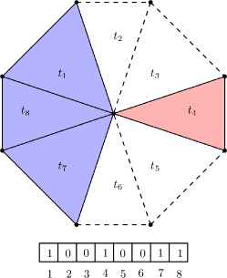
Given a polyhedron the algorithm uses a counting system to know which tetrahedrons belongs to each subpolyhedron , we create a list of all tetrahedron are adjacent to a hanging-edge , ordered in CCW or CW around , and we label those tetrahedons as a if they belong to and if they do not belong to . An example of this list is show in Figure 2, the algorithm checks the changes while we iterates over , if the algorithm changes from to means that we are in a new subpolyhedron .
After creating , we iterates over from the first element that is mark as , we search to the first change from to , we store all the tetrahedons until the change from to in a list , then we add to a list that contains all the subpolyhedrons of . We repeat this process until we reach the first element of again marked as .
5 Experiments
References
- [1] R. Alonso, J. Ojeda, N. Hitschfeld, C. Hervías, and L.E. Campusano. Delaunay based algorithm for finding polygonal voids in planar point sets. Astronomy and Computing, 22:48 – 62, 2018.
- [2] Fernando Balboa, Pedro Rodriguez-Moreno, and María-Cecilia Rivara. Terminal Star Operations Algorithm for Tetrahedral Mesh Improvement, pages 269–282. Springer International Publishing, Cham, 2019.
- [3] Sergio Salinas-Fernández, José Fuentes-Sepúlveda, and Nancy Hitschfeld-Kahle. Generation of polygonal meshes in compact space. In International Meshing Roundtable Workshop (IMR), Amsterdam, Netherlands, March 6–9 2023.
- [4] Sergio Salinas-Fernández, Nancy Hitschfeld-Kahler, Alejandro Ortiz-Bernardin, and Hang Si. Polylla: polygonal meshing algorithm based on terminal-edge regions. Engineering with Computers, May 2022.