High-energy picosecond pulses with a single spatial mode from a passively mode-locked, broad-area semiconductor laser
Abstract
We present a mode-locked semiconductor laser oscillator that emits few picosecond pulses (5-8ps at 379MHz repetition) with record peak power (112W) and pulse energy (0.5nJ) directly out of the oscillator (with no amplifier). To achieve this high power performance we employ a high-current broad-area, spatially multi-mode diode amplifier (0.3×5mm), placed in an external cavity that enforces oscillation in a single spatial mode. Consequently, the brightness of the beam is near-ideal (). Mode locking is achieved by dividing the large diode chip (edge emitter) into two sections with independent electrical control: one large section for gain and another small section for a saturable absorber. Precise tuning of the reverse voltage on the absorber section allows to tune the saturation level and recovery time of the absorber, which provides a convenient control knob to optimize the mode-locking performance for various cavity conditions.
I Introduction
Semiconductor lasers represent the industry standard for sources of coherent light due to their high electrical-to-optical efficiency, simple and robust construction, high optical power, tunability, wide range of available wavelengths (covering the entire VIS-NIR range), and low cost. Thus, the generation of ultrashort optical pulses directly from semiconductor lasers with high peak power and high spatial beam quality (brightness) is highly desired for many applications, such as: 3D micromachining of polymer materials Correa et al. (2012); Maruo et al. (1997); Kawata et al. (2001), dvanced methods of nonlinear and fluorescence microscopy Ulku et al. (2020); Colyer et al. (2012); mic (2013); Adur et al. (2016), precision measurement and frequency metrology Fortier and Baumann (2019); Maddaloni et al. (2009); Udem et al. (2002), frequency conversion Boller et al. (2000); Klein et al. (1998), direct material processing Fritsche et al. (2015); Faircloth (2003) and medical applications Michalik et al. (2021). For these applications however, the peak power of laser diodes oscillators so far is not up to par with standard solid-state or fiber lasers, such as mode-locked Ti:Sapphire lasers or Mode locked Er / Yt fiber lasers, which offer the more prevalent solution in the market currently, despite their high complexity, limited wavelength availability and higher cost.
Since the optical power of a laser diode is directly dictated by its physical area, broad area laser diodes (BAL) are an attractive route for high-power lasers competitive with solid-state lasers, while maintaining high customizability and simplicity – requiring only electrical pumping. Unfortunately, this high power of BAL diodes normally comes at the expense of degraded spatial coherence since the wide cross-section of the diode wave-guide is inherently spatially multi-mode along the slow axis.
To mitigate the degradation of brightness, many techniques were developed, ranging from shaping the spatial profile of diode laser chip itself by special fabrication techniques Ishizaki et al. (2019); Zhao et al. (2016) to configurations of coherent beam combining Shekel et al. (2020); Hanna et al. (2016); Chang et al. (2020). However, the simplest approach that maintains the simplicity of the multimode BAL chip, is placing the BAL gain medium in an external cavity Wolff et al. (2003); Chi et al. (2005); Meller et al. (2023), which shapes the spatio-temporal profile of the beam and enforces single-mode operation. The external cavity approach is advantageous for a couple of reasons – it is simple, it allows great flexibility, and requires only off-the-shelf components. However, high-power operation is difficult, mainly due to self-lasing of the diode. At high powers, even small parasitic reflections are enough to induce self-lasing inside the diode, bypassing the external feedback. In this work, we circumvent this limitation using a simple and flexible design based on an angle-cut diode, which strongly suppresses self lasing, allowing us to obtain high-power mode locked operation, as reported hereon
In a previous paper Meller et al. (2023), we have employed an external cavity to combine power and brightness from a single diode oscillator in continuous-wave operation. Here we implement a similar concept with a passively mode locked semiconductor laser to obtain both high pulse-energy and spatial coherence in a single oscillator. We achieve record results for a single diode oscillator, with pulse-energy of () and peak power (), along with a short pulse duration (), all in a highly pure spatial mode (). This is achieved in a simple design that uses no special fabrication techniques, only off-shelf components and no subsequent amplification stages. Of course, amplification and custom-made diodes are still compatible with our design, and could be used to improve our results even further. Mode locking is obtained using a diode chip with two-sections that are independently electrically controlled: a large section of the diode is pumped with forward current to act as the gain medium, and a smaller section of the diode that is reverse-biased to act as a saturable absorber with tunable saturation Rafailov and Avrutin (2013); Breuer et al. (2014); Avrutin and Rafailov (2012). We demonstrate mode-locking at even-harmonics operation Avrutin et al. (2000); Vladimirov and Turaev (2005); Sanders et al. (1991), characteristic of colliding mode-locking Bischoff et al. (1997); Martins-Filho et al. (1995), and characterize the spatial and temporal performance of the system for different harmonics.
II Experiment
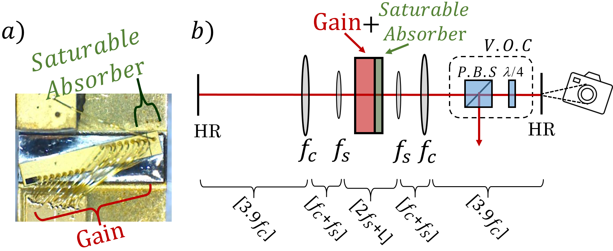
Figure 1a shows an image of the diode chip (5x0.3mm), which is cut at an angle to mitigate parasitic feedback from the diode facets that may cause self-lasing. The diode is comprised of a large gain section and the small saturable absorber section with independent electrical contacts, as marked on the image. The gain section is driven in forword current to provide amplification, whereas the absorber section is driven in reverse voltage to tune its saturation level to induce passive mode-locking and optimize its performance. This diode chip was then placed in the external cavity configuration of Figure 1b, comprised of two identical cavity arms around the diode chip (of 400mm length each). The length of each arm acts as a soft spatial filter Meller et al. (2023) that enforces oscillation in a single spatial mode. the left arm includes also a variable output coupler, implemented by a polarizing beam-splitter and a rotating wave-plate for optimizing the mode-locking performance and output power (see caption of Figure 1 for details). To stabilize the cavity for both the fast and slow axes, the diode facet is located slightly before the focal plane of a short spherical fast lens (), thereby imaging the diode facet onto the end mirror of the cavity (at 400mm distance). An additional cylindrical lens of a longer focus () is placed to form a telescope for the slow axis (together with the spherical lens). This arrangement stabilizes the slow-axis mode of the cavity and enforces single mode operation,
We evaluated the performance of our system both temporally and spatially. The temporal width of the ultrashort pulse was measured using an intensity autocorrelator (model FR-103XL with a resolution of ) and to evaluate the beam profile we employed a simple high-resolution CCD camera (Thorlabs model CS165MU with spatial resolution of ). We investigated the influence of the saturable absorber voltage on the the temporal profile of the generated pulses. In order to characterize the repetition-rate of our pulse-train and its stability, we used a fast photodetector followed by an RF spectrum analyser (Keysight model N9020A).
III Results
Table 1 summarizes the measured performance of our laser for various harmonics of the fundamental repetition rate (2nd-to-8th with repetition rates of ). Since pulses were formed only for even harmonics of the repetition rate, we suspect that the interaction between colliding pulses in the gain medium was involved in the mode-locking mechanism Bischoff et al. (1997); Martins-Filho et al. (1995), but to verify this further studies will be needed. For the 2nd harmonic we obtained high pulse energy of and pulse duration. The spatial purity of the beam was practically single-mode with and fractional power in the main spatial lobe of for all the harmonics.
| Performance and parameters | |||||||
|---|---|---|---|---|---|---|---|
| # Harmonic | Pulse energy [pJ] | Peak power [W] | Average power [mW] | Pulse duration [ps] | TBP | Current [A] | Reverse voltage [V] |
| 2nd | 551 | 112.6 | 209 | 4.9 | 5.7 | 5.19 | 4.2 |
| 4th | 366 | 69.9 | 278 | 5.2 | 3.5 | 5.21 | 3.6 |
| 6th | 400 | 67.3 | 455 | 5.9 | 3.3 | 5.53 | 2.3 |
| 8th | 407 | 51.57 | 618 | 7.9 | 5.7 | 6.11 | 1.5 |
Figure 2 provides a comparison of the obtained pulse performance to previously published systems in the literature. As evident, our pulse energies surpass previously published work by 1-2 orders of magnitude, while our peak power is 1-2 orders of magnitude higher than all ps-range sources, comparable only to fs-range oscillators (marked by a blue dashed circle on the figure) that have much lower pulse energy. Note that the pulse duration of our laser was far from minimal and not transform limited (with time-bandwidth product of 5.7 for the lowest harmonic) since our laser configuration did not include any measure for dispersion compensation, whereas the works circled with dashed blue in the figure did. Hopefully, proper dispersion compensation can push our pulse duration down as well, allowing to achieve higher peak powers at similar pulse energies.
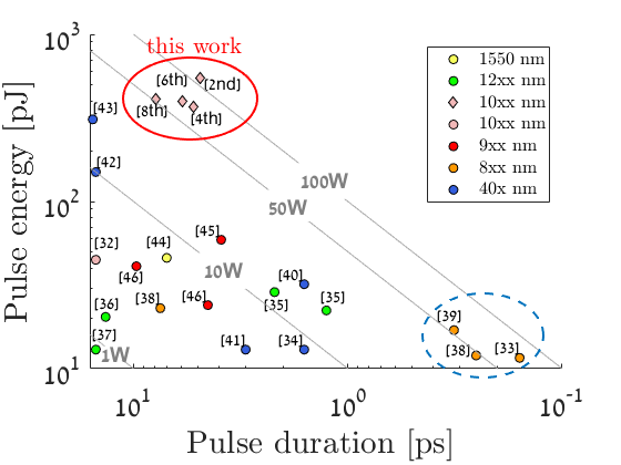
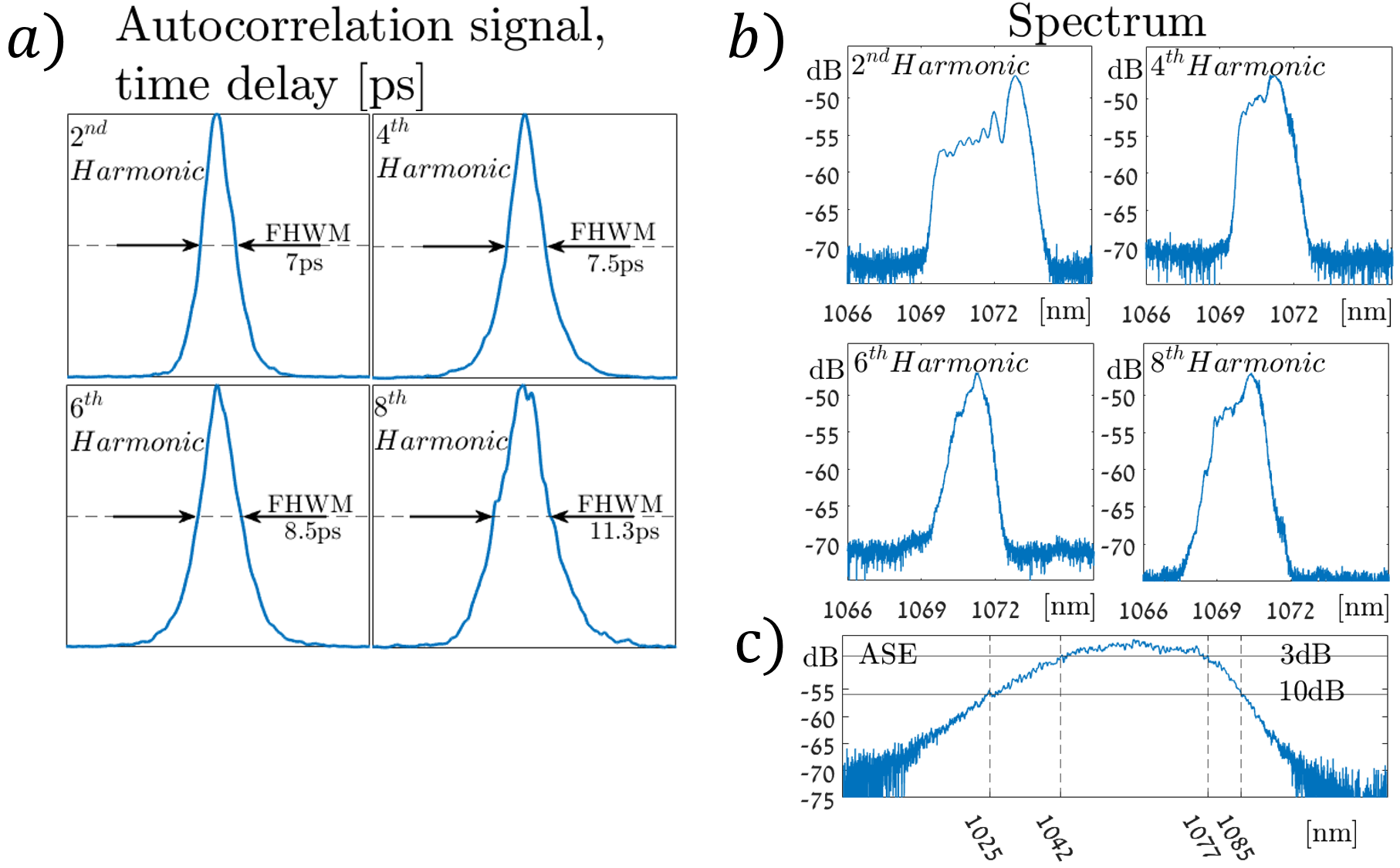
Figure 3 provides details of the measured pulses in both time and optical frequency. Figure 3a shows the auto-correlation traces of the different rep-rate harmonics and Figure 3b shows the optical spectrum of each harmonics, as well as the spontaneous-emission spectrum Figure 3c (the spectral gain curve). Clearly, the pulses are not transform limited as summarized in the table 1 above.
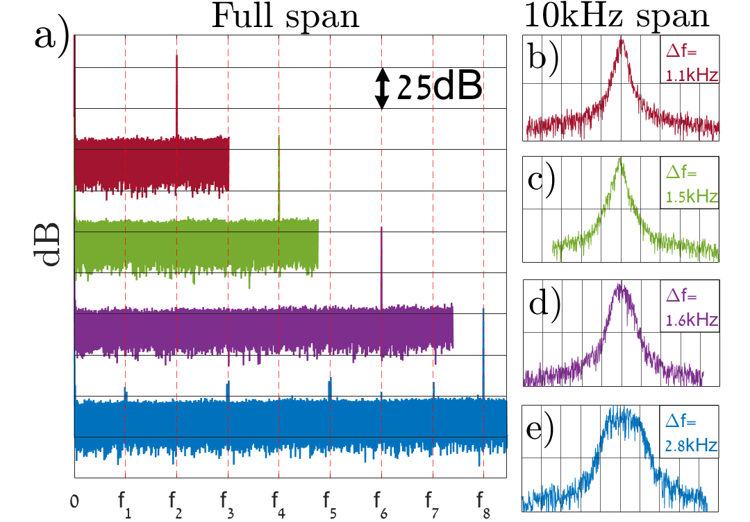
The stability and purity of the generated pulse train is illustrated in Figure 4. We analysed the RF spectrum of the pulse train, as measured on a fast photo-detector. A clean trace of the RF spectrum is obtained for 2nd,4th and 6th harmonics, showing only the oscillation rep-rate (and multiples) without any sub-harmonics or spurious frequencies (down to 50dB) below the, which indicates a clean, stable pulse train, whereas the 8th harmonics starts showing rep-rate instabilities. Detailed RF spectra of the rep-rate frequency are shown in figures 4b-e, where the observed line-widths is primarily due to the passive stability of the cavity length (which is not stabilized here at all).
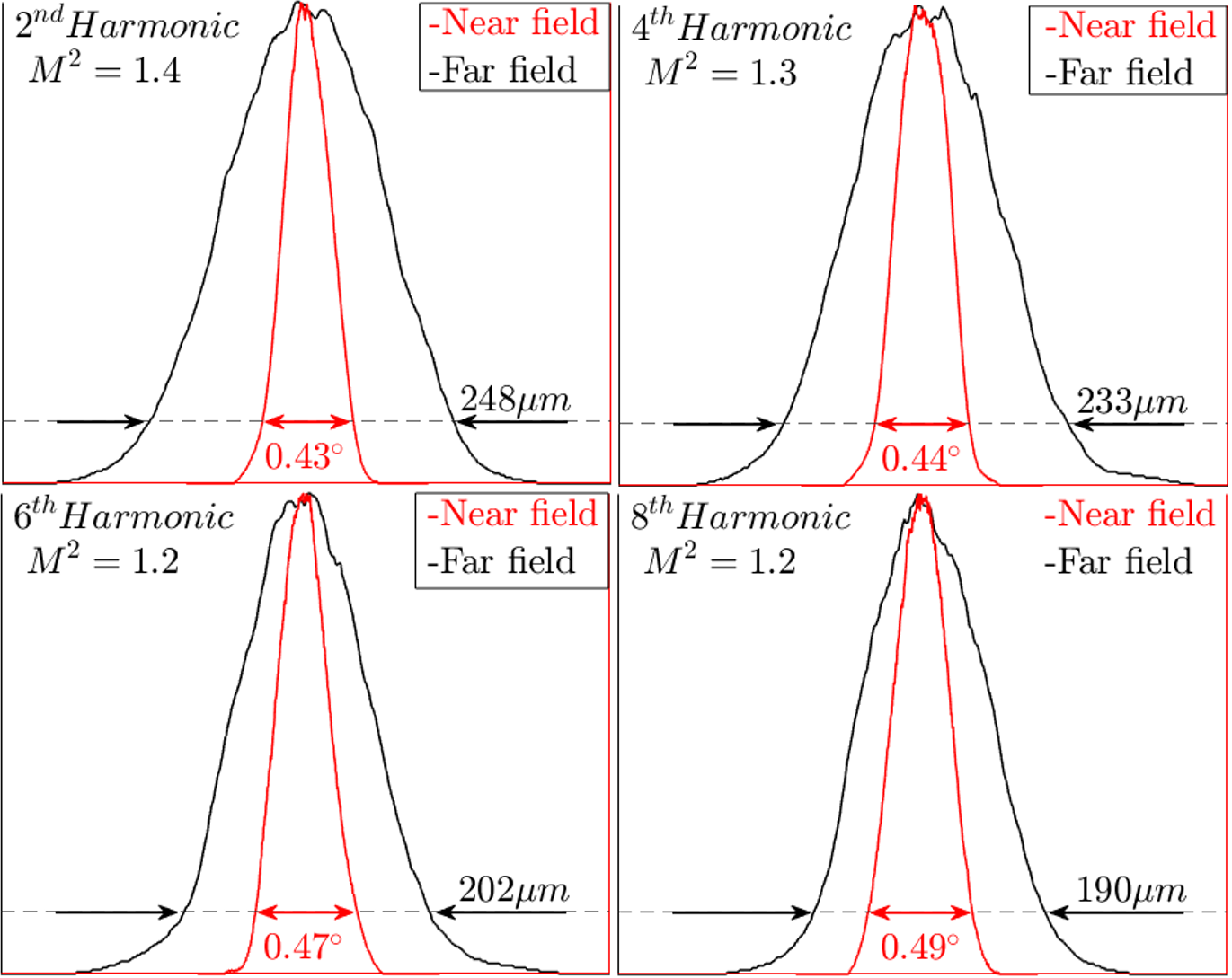
Finally, our high-energy pulses are achieved with high spatial coherence, as illustrated in Fig. 5. Specifically, is achieved for all the harmonics, indicating a near-ideal spatial mode with high brightness and focusability.
IV Conclusions
In conclusion, we present an external cavity configuration that implements passive mode-locking in a broad-area dual-section diode - a gain section with forward current and an integral saturable absorver section with a voltage controlled saturation level. The diode chip is cut at an angle to mitigate self-lasing at the diode facets. Our results demonstrate ps-range pulses with record performance in terms of pulse energy and peak power. The simplicity of the external cavity configuration that produces such high-energy and high-brightness ultrafast pulses is attractive for a wide range of applications, including laser micromachining, precision metrology, and nonlinear optics.
The Possibility to produce even shorter, sub-ps pulses by incorporation of dispersion control in the cavity is fascinating and will be the focus of future research.
References
- Correa et al. (2012) D. S. Correa, M. R. Cardoso, V. Tribuzi, L. Misoguti, and C. R. Mendonca, IEEE Journal of Selected Topics in Quantum Electronics 18, 176 (2012).
- Maruo et al. (1997) S. Maruo, O. Nakamura, and S. Kawata, Optics Letters 22, 132 (1997).
- Kawata et al. (2001) S. Kawata, H.-B. Sun, T. Tanaka, and K. Takada, Nature 412, 697 (2001).
- Ulku et al. (2020) A. Ulku, A. Ardelean, M. Antolovic, S. Weiss, E. Charbon, C. Bruschini, and X. Michalet, Methods and Applications in Fluorescence 8, 024002 (2020).
- Colyer et al. (2012) R. A. Colyer, O. H. W. Siegmund, A. S. Tremsin, J. V. Vallerga, S. Weiss, and X. Michalet, Journal of Biomedical Optics 17, 016008 (2012).
- mic (2013) “Nonlinear optical microscopy,” (2013).
- Adur et al. (2016) J. Adur, H. F. Carvalho, C. L. Cesar, and V. H. Casco, in Microscopy and Analysis (InTech, 2016).
- Fortier and Baumann (2019) T. Fortier and E. Baumann, Communications Physics 2 (2019), 10.1038/s42005-019-0249-y.
- Maddaloni et al. (2009) P. Maddaloni, P. Cancio, and P. D. Natale, Measurement Science and Technology 20, 052001 (2009).
- Udem et al. (2002) T. Udem, R. Holzwarth, and T. W. Hänsch, Nature 416, 233 (2002).
- Boller et al. (2000) K.-J. Boller, B. Beier, and R. Wallenstein, “Properties and frequency conversion of high-brightness diode-laser systems,” in High-Power Diode Lasers: Fundamentals, Technology, Applications: With Contributions by Numerous Experts, edited by R. Diehl (Springer Berlin Heidelberg, Berlin, Heidelberg, 2000) pp. 225–263.
- Klein et al. (1998) M. Klein, D.-H. Lee, J.-P. Meyn, B. Beier, K.-J. Boller, and R. Wallenstein, Optics letters 23, 831 (1998).
- Fritsche et al. (2015) H. Fritsche, F. Ferrario, R. Koch, B. Kruschke, U. Pahl, S. Pflueger, A. Grohe, W. Gries, F. Eibl, S. Kohl, and M. Dobler, in High-Power Laser Materials Processing: Lasers, Beam Delivery, Diagnostics, and Applications IV, Vol. 9356, edited by F. Dorsch, International Society for Optics and Photonics (SPIE, 2015) p. 93560I.
- Faircloth (2003) B. O. Faircloth, in High-Power Diode Laser Technology and Applications, Vol. 4973, edited by M. S. Zediker, International Society for Optics and Photonics (SPIE, 2003) pp. 34 – 41.
- Michalik et al. (2021) M. Michalik, J. Szymańczyk, M. Stajnke, T. Ochrymiuk, and A. Cenian, Micromachines 12 (2021), 10.3390/mi12060710.
- Ishizaki et al. (2019) Ishizaki, Zoysa, and Noda, Photonics 6, 96 (2019).
- Zhao et al. (2016) D. Zhao, S. Liu, H. Yang, Z. Ma, C. Reuterskiöld-Hedlund, M. Hammar, and W. Zhou, Scientific Reports 6 (2016), 10.1038/srep18860.
- Shekel et al. (2020) E. Shekel, Y. Vidne, and B. Urbach, in Fiber Lasers XVII: Technology and Systems, edited by L. Dong and M. N. Zervas (SPIE, 2020).
- Hanna et al. (2016) M. Hanna, F. Guichard, Y. Zaouter, D. N. Papadopoulos, F. Druon, and P. Georges, Journal of Physics B: Atomic, Molecular and Optical Physics 49, 062004 (2016).
- Chang et al. (2020) H. Chang, Q. Chang, J. Xi, T. Hou, R. Su, P. Ma, J. Wu, C. Li, M. Jiang, Y. Ma, and P. Zhou, Photonics Research 8, 1943 (2020).
- Wolff et al. (2003) S. Wolff, A. Rodionov, V. Sherstobitov, and H. Fouckhardt, IEEE Journal of Quantum Electronics 39, 448 (2003).
- Chi et al. (2005) M. Chi, B. Thestrup, and P. M. Petersen, Optics Letters 30, 1147 (2005).
- Meller et al. (2023) M.-E. Meller, I. Parshani, L. Bello, D. Goldovsky, A. Kahana, and A. Pe’er, IEEE Journal of Quantum Electronics 59, 1 (2023).
- Rafailov and Avrutin (2013) E. Rafailov and E. Avrutin, in Semiconductor Lasers (Elsevier, 2013) pp. 149–217.
- Breuer et al. (2014) S. Breuer, D. Syvridis, and E. U. Rafailov, “Ultra-short-pulse QD edge-emitting lasers,” (2014).
- Avrutin and Rafailov (2012) E. Avrutin and E. Rafailov, in Advances in Semiconductor Lasers (Elsevier, 2012) pp. 93–147.
- Avrutin et al. (2000) E. Avrutin, E. Portnoi, and J. Marsh, IEE Proceedings - Optoelectronics 147, 251 (2000).
- Vladimirov and Turaev (2005) A. G. Vladimirov and D. Turaev, Physical Review A 72 (2005), 10.1103/physreva.72.033808.
- Sanders et al. (1991) S. Sanders, A. Yariv, J. Paslaski, J. E. Ungar, and H. A. Zarem, Applied Physics Letters 58, 681 (1991).
- Bischoff et al. (1997) S. Bischoff, J. Mørk, T. Franck, S. D. Brorson, M. Hofmann, K. Fröjdh, L. Prip, and M. P. Sørensen, Quantum and Semiclassical Optics: Journal of the European Optical Society Part B 9, 655 (1997).
- Martins-Filho et al. (1995) J. Martins-Filho, E. Avrutin, C. Ironside, and J. Roberts, IEEE Journal of Selected Topics in Quantum Electronics 1, 539 (1995).
- Rosales et al. (2014) R. Rosales, V. P. Kalosha, K. Posilović, M. J. Miah, D. Bimberg, J. Pohl, and M. Weyers, Applied Physics Letters 105 (2014), 10.1063/1.4899129.
- Balzer et al. (2013) J. Balzer, T. Schlauch, A. Klehr, G. Erbert, G. Tränkle, and M. Hofmann, Electronics Letters 49, 838 (2013).
- Koda et al. (2012) R. Koda, T. Oki, S. Kono, T. Miyajima, H. Watanabe, M. Kuramoto, M. Ikeda, and H. Yokoyama, Applied Physics Express 5, 022702 (2012).
- Nikitichev et al. (2012a) D. I. Nikitichev, Y. Ding, M. A. Cataluna, E. U. Rafailov, L. Drzewietzki, S. Breuer, W. Elsaesser, M. Rossetti, P. Bardella, T. Xu, I. Montrosset, I. Krestnikov, D. Livshits, M. Ruiz, M. Tran, Y. Robert, and M. Krakowski, Laser Physics 22, 715 (2012a).
- Ding et al. (2010) Y. Ding, D. Nikitichev, I. Krestnikov, D. Livshits, M. Cataluna, and E. Rafailov, Electronics Letters 46, 1516 (2010).
- Nikitichev et al. (2012b) D. I. Nikitichev, K. A. Fedorova, Y. Ding, A. Alhazime, A. Able, W. Kaenders, I. Krestnikov, D. Livshits, and E. U. Rafailov, Applied Physics Letters 101, 121107 (2012b).
- Schlauch et al. (2010) T. Schlauch, J. C. Balzer, A. Klehr, G. Erbert, G. Tränkle, and M. R. Hofmann, Optics Express 18, 24316 (2010).
- Balzer et al. (2015) J. C. Balzer, R. H. Pilny, B. Dopke, A. Klehr, G. Erbert, G. Trankle, C. Brenner, and M. R. Hofmann, IEEE Journal of Selected Topics in Quantum Electronics 21, 16 (2015).
- Oki et al. (2011) T. Oki, R. Koda, S. Kono, T. Miyajima, H. Watanabe, M. Kuramoto, M. Ikeda, and H. Yokoyama, Applied Physics Letters 99 (2011), 10.1063/1.3640499.
- Koda et al. (2010) R. Koda, T. Oki, T. Miyajima, H. Watanabe, M. Kuramoto, M. Ikeda, and H. Yokoyama, Applied Physics Letters 97 (2010), 10.1063/1.3462942.
- Watanabe et al. (2010a) H. Watanabe, T. Miyajima, M. Kuramoto, M. Ikeda, and H. Yokoyama, Applied Physics Express 3, 052701 (2010a).
- Watanabe et al. (2010b) H. Watanabe, M. Kuramoto, S. Kono, M. Ikeda, and H. Yokoyama, Applied Physics Express 3, 122103 (2010b).
- Ahmad and Rana (2008) F. R. Ahmad and F. Rana, IEEE Photonics Technology Letters 20, 190 (2008).
- Wang et al. (2019) Y. Wang, X. Zhang, C. Tong, L. Wang, S. Shu, and L. Wang, Applied Physics Express 12, 102011 (2019).
- Ding et al. (2013) Y. Ding, W. Ji, J. Chen, S. Zhang, X. Wang, H. Wang, H. Ni, J. Pan, B. Cui, and M. A. Cataluna, in SPIE Proceedings, edited by A. A. Belyanin and P. M. Smowton (SPIE, 2013).