NASU – Novel Actuating Screw Unit:
Origami-inspired Screw-based Propulsion on Mobile Ground Robots
Abstract
Screw-based locomotion is a robust method of locomotion across a wide range of media including water, sand, and gravel. A challenge with screws is their significant number of impactful design parameters that affect locomotion performance in varying environments. One crucial parameter is the angle of attack, also referred to as the lead angle. The angle of attack has a significant impact on the screw’s performance as it creates a trade-off between efficiency and forward velocity. This trend is consistent across various types of media. In this work, we present a Novel Actuating Screw Unit (NASU). It is the first screw-based propulsion design that enables the reconfiguration of the angle of attack dynamically for optimized locomotion across multiple media. The design is inspired by the kresling unit, which is a widespread mechanism in origami robotics, and the angle of attack is adjusted with a linear actuator, while the entire unit is spun on its axis as an archimedean screw. NASU is integrated onto a mobile test-bed and experiments are conducted in a large variety of media including gravel, grass, and sand. Our experiments show the proposed design is a promising direction for reconfigurable screws by allowing control to optimize for efficiency or velocity.
I Introduction
Archimedean screws were first used, in terms of locomotion mechanisms, as propellers for watercraft [1, 2], and later proposed for amphibious vehicles capable of traversing and transporting loads in both liquid and soil environments [3, 4]. Screw-propelled vehicles and rovers have since demonstrated success across a very wide range of environments including snow, ice, sand, and other granular media [5, 6]. These screw-based designs have great potential for exploratory robots, overcoming limitations faced by traditional wheeled rover designs and potentially avoiding situations like NASA’s Spirit rover getting stuck in loose sand on Mars [7]. Most screw-based designs use a parallel configuration where two counter-rotating, opposite-handed screws allow for turning [8, 9]. Quad-screw designs have been proposed to take advantage of a partial screw-slippage case for omnidirectional drive [10, 11]. To maintain more points of contact and increase versatility, hyper-redundant snake-like designs have also been proposed. One such robot is ARCSnake [12, 13], which combines Archimedean screw-based propulsion and serpentine body reshaping, and is the evolutionary precursor to the NASA Extant Exobiology Life Surveyor (EELS) robot [14]. EELS is anticipated to serve as a science research vehicle for both earth science missions as well as for space exploration missions on Enceladus and Europa [14]. Deployments of the robot types mentioned above are often in resource-constrained environments where adaptability is crucial.
I-A Contributions
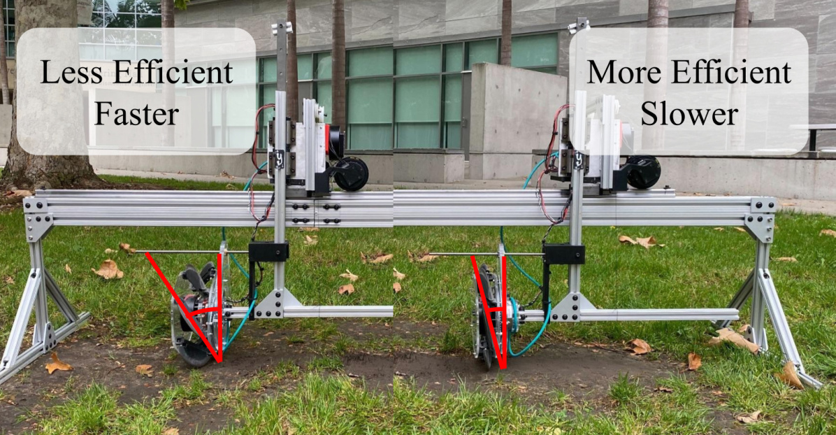
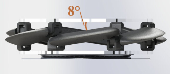
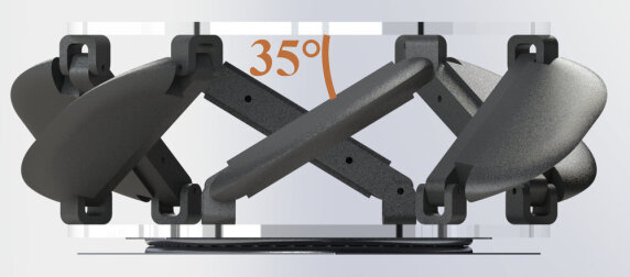
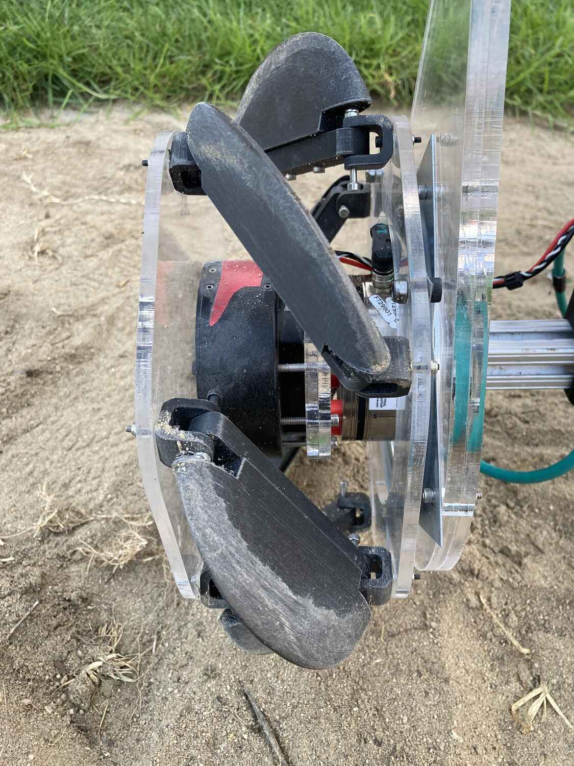
In this paper, we present the Novel Actuator Screw Unit (NASU) which is a screw propulsion unit design that enables an adjustable angle of attack through inspiration from the kresling unit, a popular mechanism in origami robotics [15, 16, 17, 18]. However, unlike origami robotics which are often made from compliant materials, NASU is designed to withstand the high loads in screw-based locomotion [19]. A linear actuator is used to control the kresling unit, providing a means for changing the angle of attack dynamically within a range of 10-35°. NASU’s mechanism for adjusting the angle of attack allows for on-the-fly re-configurations, thereby enabling intelligent control for either higher velocity or efficiency as required for different mission objectives (see Figure 1). Ultimately, NASU offers a novel, adjustable screw-based locomotion approach for mobile robots for multi-domain deployments.
I-B Related Works
A challenge for screw-based locomotion designs is the significant number of design parameters that can affect performance. In the specific case of sand-like media, significant exploration has been done into the effect of varying certain parameters such as angle of attack (also referred to as lead angle, pitch angle, and helix angle in previous literature), blade height, and blade profile [20, 21, 22, 23]. These studies showed that performance is greatly affected by the angle of attack, estimating a maximum thrust achieved at an angle of around 22° [24], which was then used in previous screw-based designs [13, 12]. The ideal ratio between the screw diameter and length of the screw has also been found [10]. However, it has been shown that for a fixed set of parameters, performance varies significantly across different media and there is an inherent trade-off between traveling velocity and efficiency when picking the angle of attack [19].
Outside of screw-based locomotion, reconfiguration for aerial locomotion has been explored in nature to understand how changing parameters of bird wings affect flight performance [25, 26]. Similar abilities have been replicated in robotics to achieve more efficient flight performance from wing designs [27]. Reconfigurable propeller designs have also been proposed to create more efficient propulsion in different scenarios [28, 29]. In a similar fashion, we present NASU which can dynamically adjust the angle of attack to reconfigure the locomotion capabilities.
II System Design
The NASU design, as noted previously, takes inspiration from the origami kresling unit. However, modifications were made to ensure performance and durability in different and more challenging media. The new design could be described as a twist on a Stewart platform, and its operation is shown in Figure 3.
In this current design, the kresling unit structure is actuated by augmenting and controlling the total length of the unit to facilitate the changing of the angle of the blades.
In our design, we verified the ability to produce appropriate thrust force and withstand reaction forces based on previous literature that captured data on screw forces.
Finally, we provided a means to integrate the NASU into a mobile testing platform which provided a means to gather on performance across media.
II-A Mechanical Design
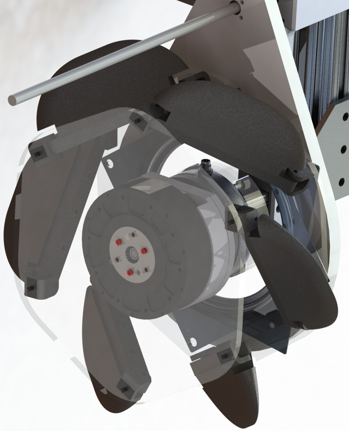
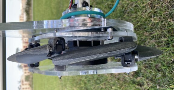
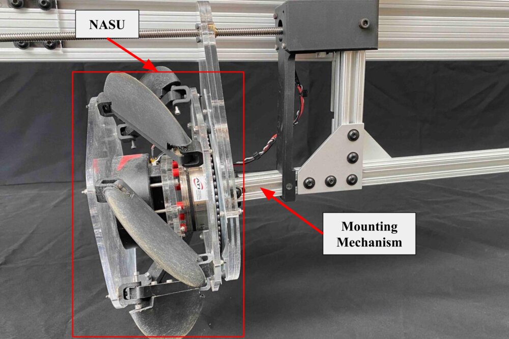
An overview of the mechanical design can be seen in Figure 2 which depicts an isolated unit actuated with a linear ball screw and a Nema-17 stepper motor. The motor housing is fixed to the test bed [19] vertical rail and the linear ball screw carriage is connected to the back plate. The actuator drives the position of the back plate which will cause the length to increase or decrease depending on direction. When the distance between plates is increased the angle of attack also increases, as described in the following equations:
| (1) | |||
| (2) |
where the distance between the inner surfaces of the plates is denoted by , is the sum of the offsets between the plates and the pivot points (the second pin joint center of the U-joint joint), is the length of the link that connects the pivot points, and is the angle of attack. In our design, , and . The diameter and strut length were chosen to ensure our required angle range.
The NASU was built using 3D printed and acrylic parts with a root radius of 192 mm, and an outer radius of 272 mm. The length range is 48-88 mm and the adjustable angle of attack is between 10-35 °. The hexagonal base proscribes six-thread starts. These parameters were chosen to match similar ratios with previous literature [13, 10]. The blade design in terms of height, shape, and profile was inspired by previous work [23].
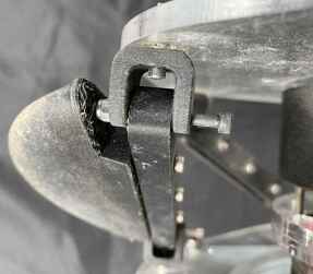
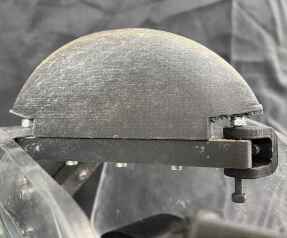
Each unit has 3 key features: u-joint connecting the front/back plate to the struts, replaceable blade attachment points along the struts, and blades. The u-joint consists of 2 pin joints perpendicular to each other created from the strut and a U-bracket shown in Figure 4(a). The struts are designed with through holes to allow for the replacement of the blades to augment height, profile shape, and length shown in Figure 4(b). Finally, the blades themselves contain heat-set inserts to allow for easy swapping between blades with different parameters.
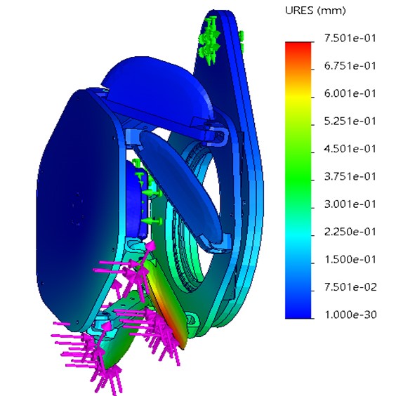
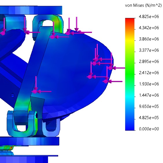
Finite Element Analysis (FEA) was done using a static Solidworks Simulation model. A static hold is considered the highest force-producing scenario as it indicates a stalled position in media giving the highest reaction force back against the blades. The NASU was set to its 35° configuration as it would also be the highest thrust-producing configuration, and have the highest resultant reaction force. The connections between NASU and the testbed were set as the fixture points. Pin connections were used to model the correct degrees of freedom of the u-joint. The external loads that were applied were taken from previous work [19]. The forces were collected from an earlier version of the testbed described in III. In that work, a load cell (6-DoF Force Torque Sensor (FTS), Axia80 (ATI Industrial Automation)) was used to collect data on the forces and torques loading the system. To ensure our design was strong enough to withstand maximum loading on all media and directions we took the peak forces across media and trials in each principle direction and produced a maximal load based on all those combined. The maximum values are, . Where +Z is forward, +X is down, aligned with gravity, and +Y is pointing to the right following the right-hand rule. In the previous works’ experiments, gravity was removed by taring the senor, thus we added a representative gravity back into the X vector by taking the effective mass (1.1kg) of NASU and multiplying it by gravity . It was not necessary to account for the geometry change between the previous screw design and the NASU unit as we are applying the same maximum forces produced by the material which is unaffected by screw geometry. The applied forces for the simulation are . Their magnitude is .
The resulting numbers were a minimum Factor of Safety (FOS) of 9.9, a max displacement of 0.75 mm, a max stress of N/m2, and a maximum strain of ESTRN. The visual results can be seen in figure 5 which depicts the entire NASU unit under load with deflection measurements and highlights the u-joint under load with stress measurements reflected across the joint.
II-B Mobile Test Bed: NASU Actuation
We reuse the Mobile Test Bed from our previous work [19] to hold NASU and use it for experiments and results. The Mobile Test Bed was designed for experiments to be done “in the real world” thus enabling more significant evidence of the viability and robustness of the design. Furthermore, it was built for easy swapping of different screw configurations which we used to mount NASU.
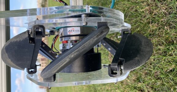
Through the mobile test bed, NASU is constrained to travel in a single, linear direction through linear rails. Traveling velocity is measured on the linear-travel rail with a passive RMD-L 7015 motor. Meanwhile, the height-adjusting linear rail helps compensate for potentially uneven surfaces being experimented on. Finally, a 6-DoF FTS, Axia80 (ATI Industrial Automation), is positioned near the center of mass to measure the screw’s applied torque and resulting screw-locomotion forces.
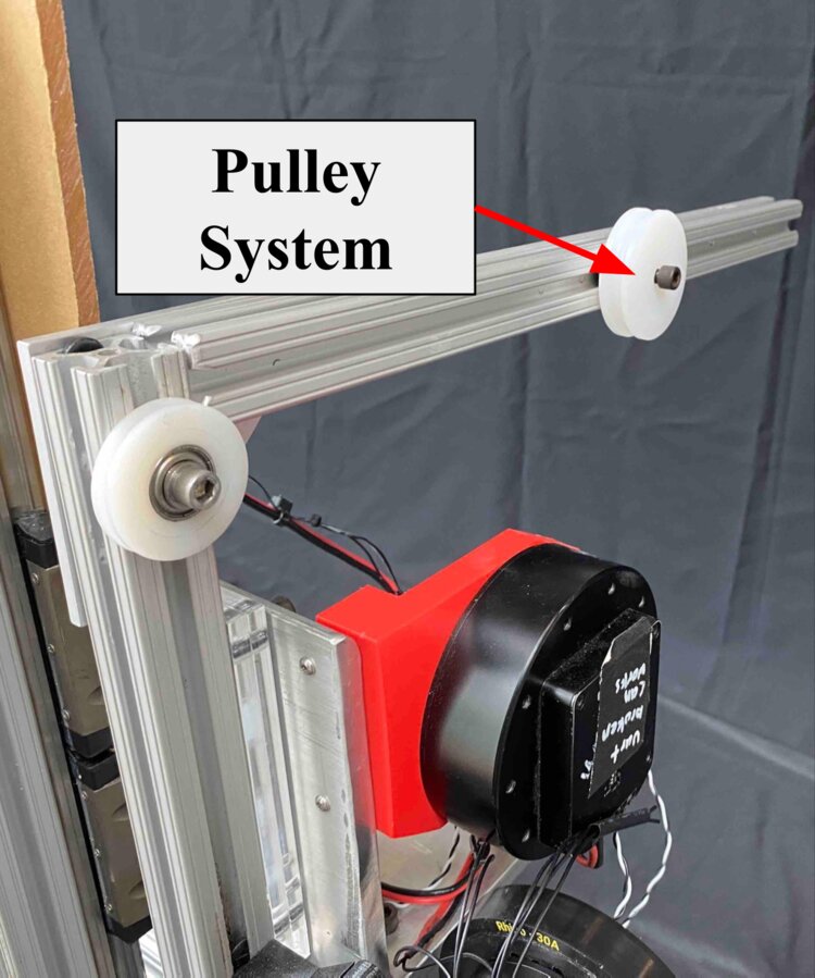
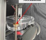
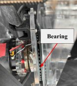
To actuate the NASU during testing, modifications were added to the test bed to ensure proper transitions between angles of attack for best results. The additions included: (1) a pulley system to add counterweight (2) an attachment and connecting mechanism for the same Nema-17 stepper motor (3) an additional bearing to ensure the rotational degree of freedom (twist) needed to allow for control over the angle of attack. An overview of our changes is shown in Figure 6.
The vertical bar on the testbed and NASU together are quite massive and require some counterweighting to avoid continually digging into media rather than propelling on the surface. This enables proper measurement with the FTS. This feature can be seen in Figure 6(b). In the transition onto the test bed, it was necessary to design an actuation method that would not hinder or invalidate the data collection. Therefore we designed a means to control the screw length, hence adjusting the angle of attack, through the linear actuator mentioned previously. The motor housing was secured to the vertical bar of the test bed as seen in Figure 6(c). Lastly, in order for the Kresling unit design to properly morph to new angles of attack it was necessary to maintain a torsional degree of freedom which was accomplished through the addition of a lazy susan bearing sandwiched between the back plate of the NASU unit and the constraining plate driven by the linear actuator. The bearing is shown in Figure 6(d).
III Experiments and Results
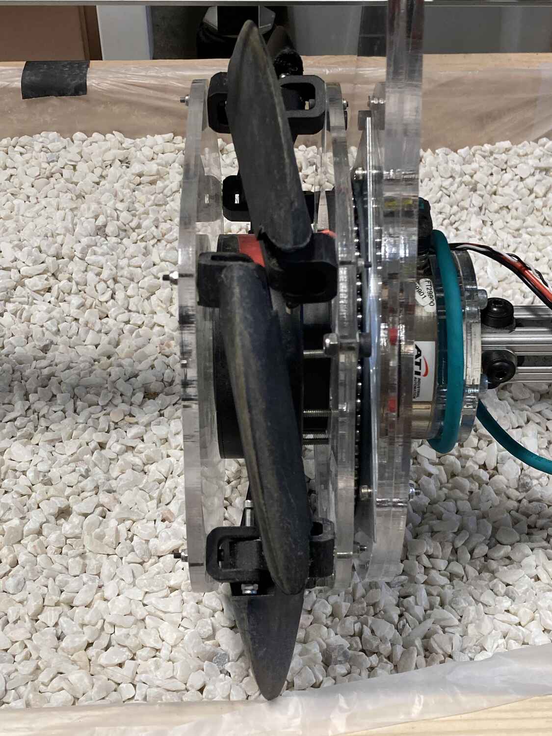
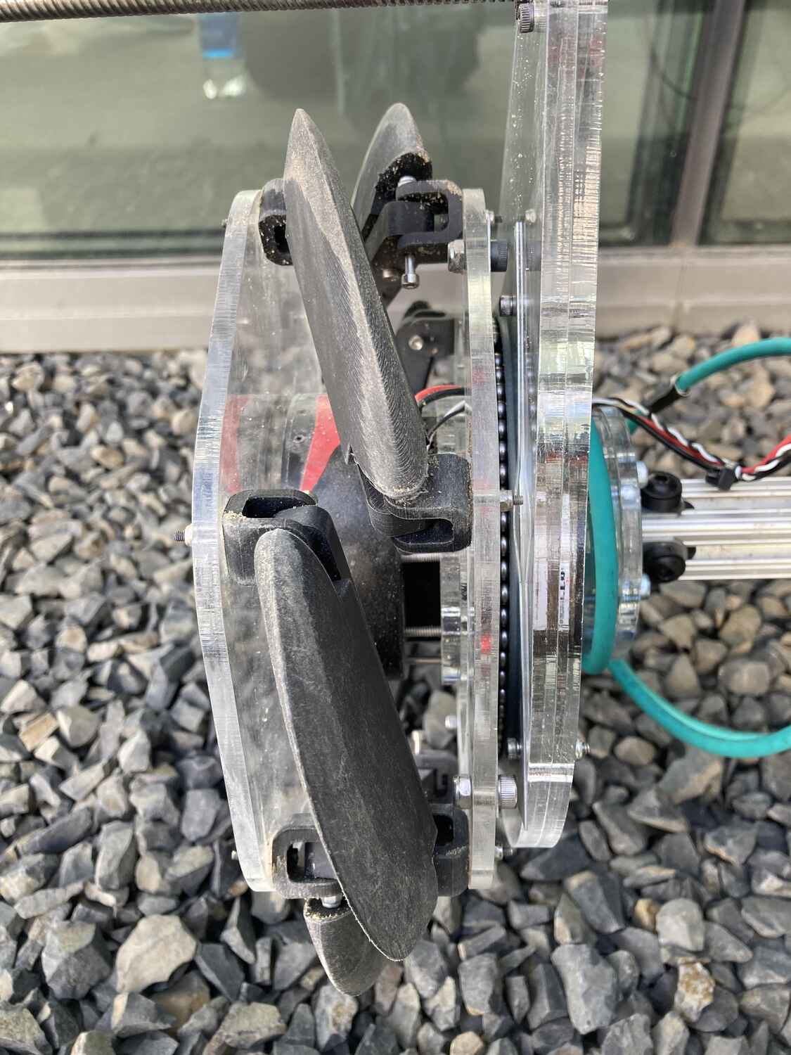
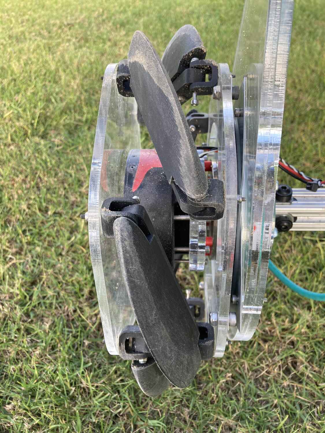
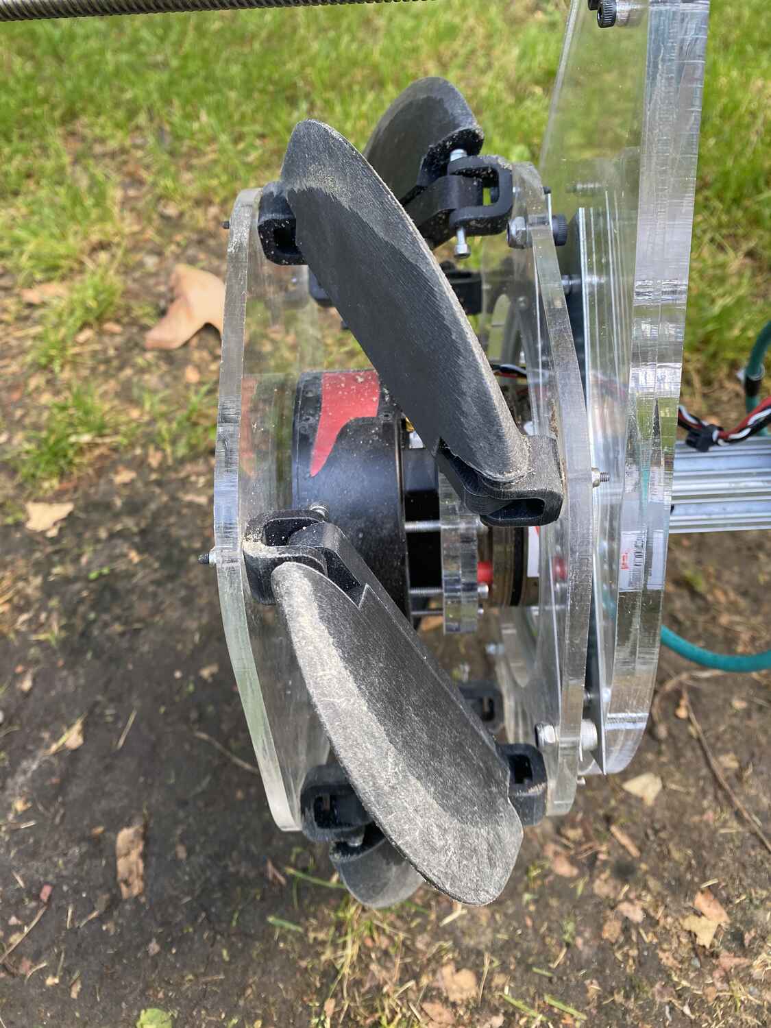
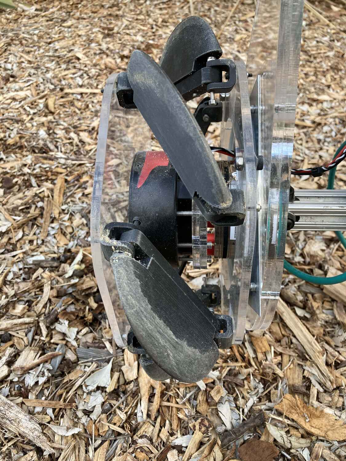
Experiments are conducted with the NASU on a mobile test bed in a wide range of media in both a lab setting and in real-world environments as shown in Figure 7. These experiments characterize the locomotion performance at varying angles of attack on each media to provide comprehensive efficiency results of NASU.
III-A Experimental Setup
The experiment is conducted on our previously developed Mobile Test Bed [19] and a similar experimental setup procedure is employed:
-
1.
Flatten and level the media to achieve as uniform conditions as possible.
-
2.
The height-adjustable linear rail is locked such that the NASU is free-hanging. A “free hanging” measurement from the FTS is taken to capture any potential drifts between trials. The angle of attack is set to the desired value.
-
3.
The height-adjustable linear rail is unlocked and the NASU is set down on the media. A “set down” measurement from the FTS is taken to measure any pre-loading from the media on the NASU.
-
4.
The FTS sensor is zeroed to measure differential measurements.
From this point, the screw motor can be driven to begin the experiment. To process the raw data from the test bed for analysis, the data from the motors and FTS are passed through a low pass filter with a cutoff frequency of 5 Hz and a sampling frequency of 125 Hz. The data is clipped manually to only include the steady-state portion of the experiment. This experiment allows freedom of motion in both the axial and vertical directions so that the speed of travel can be measured and sink-age into the media is still allowed. In contrast, all other degrees of freedom are restricted by the test bed. The angles of attack being tested are 10°, 15°, 20°, 25°, 30°, and 35°.
III-B Performance Evaluation
Two extremely relevant metrics that characterize performance are linear traveling velocity, measured directly by the mobile testbed, and locomotive efficiency. Locomotive efficiency is defined as follows:
| (3) |
where is the force produced by the NASU along its longitudinal axis, is the linear traveling velocity, and and are the average input torque and angular velocity, respectively. Because there is substantial noise in our measurements due to conducting experiments in real, outdoor environments, we use the average velocity over the entire trial and maximum force within the trial to compute the highest achievable efficiency our novel mechanism can produce on that media.
III-C Results and Discussion
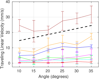
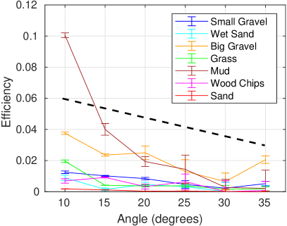
The results are shown in Figure 8. As might be expected, there is a positive correlation between the angle of attack and forward velocity. If we consider our ability to produce thrust directly related to our ability to move mass backward this aligns with the theoretical models for screws and screw-style propulsion. Similarly when the angle of attack is held to a lower value each revolution of the screw pushes the mass of the material less distance and therefore the screw moves forward less. In this experiment, we did not see the expected velocity drop off as you would see in winged aircraft in which an increase in angle of attack would produce a higher drag. However, a key finding of our experiments is that locomotive efficiency actually decreases as the angle of attack increases, implying a trade-off between speed and efficiency that is consistent across all of the media that we tested. This reinforces the fact that changes in the angle of attack affect the performance of the screw.
We believe the trade-off between linear traveling velocity and efficiency is because
-
1.
for a given input torque, thrust force increases with decreasing angle of attack, compensating for the decrease in speed, and
-
2.
as the angle of attack increases, the blades push more material to the sides and have more of an excavating effect, thus losing far more energy to the displacement of media.
As seen in the experimental results, NASU’s operating range for angle of attack sufficiently covers this trade-off. Figure 1 gives a simple diagram comparing the maximum and minimum angles of attack, as well as labeling the trade-off.
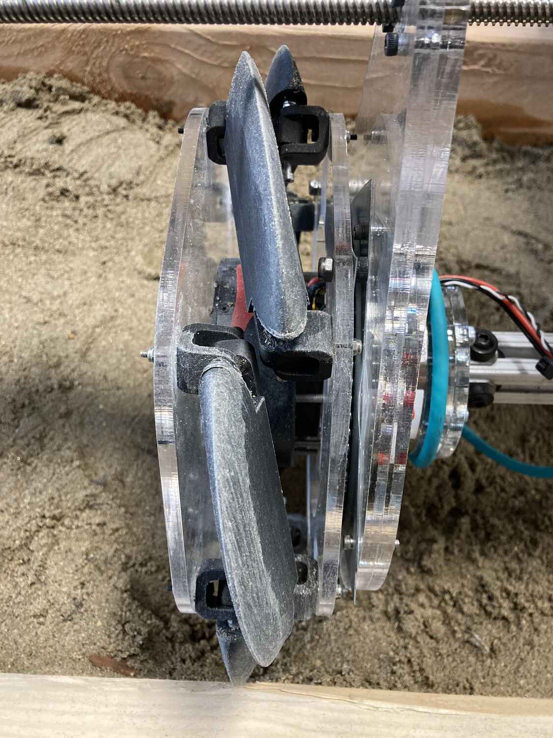
We find that the relative performance across different media types compares well with previous research on screw-based locomotion performance [19], which suggested that shearing force and coefficient of friction are two main properties contributing to variance in performance across media. In this work, the best performance was obtained in mud, which was compact enough to provide a high shearing force, while still allowing the blades to sink in smoothly and gain traction well. Big gravel and small gravel exhibit the next best performance, respectively. These media also provide a high shearing force and have a lower coefficient of friction compared to other media, although the granularity of the gravel leads to more sporadic, bumpy movement and energy lost to vertical instead of horizontal motion. Meanwhile we we were unable to produce significant propulsion in sand due to NASU pushing the material to the side rather than propelling with it. An example from our experiments is shown in Figure 9.
The most similar model which moves media in this fashion is Archimedes screws. Originally used to transport water to higher potential energy reservoirs. These designs involve an internal screw or auger with a pipe wall (tube) surrounding the mechanism. The mechanism works by constraining the motion of the fluid to a confined space that traverses up the tube. This control volume of material can be achieved in screw-based robots when there is an internal chamber and the material shears easily creating an outer wall of static material.
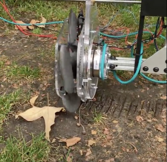
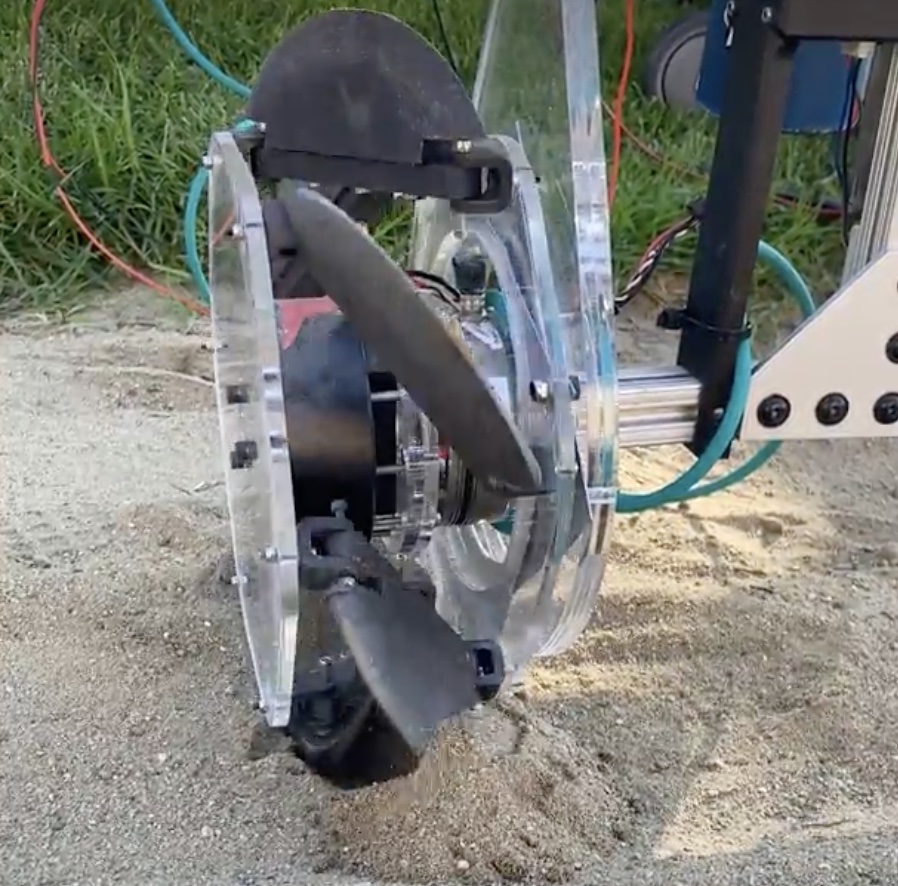
Given the lack of an internal shell our NASU unit would not be able to replicate this ideal model. Figure 9 implies that sand is the most severely affected by the lack of an internal shell. It cannot constrain the motion of the media to propel itself forward efficiently. Pressure and a physical bearer were required to ensure the constrained volumetric motion of the sand.
One other note of difference in the designs was the length of the blades. On the NASU the blades are short and plenty. Most of the screw shell designs have a single or few threads that travel a longer path around the screw. This means the media has a continuous force applied rather than short bursts of force applied in a discontinuous fashion. In future designs, it would be advantageous to either make a longer single unit or stack NASU units to create a more continuous helical pattern across the screw surface.
IV Conclusion
This work demonstrates the first mechanism to reconfigure a screw parameter for mobility by changing the angle of attack of a screw actuator to allow for dynamic adjustment between locomotion efficiency and traveling velocity on various media. The experimental results support that we do capture the trade-off between traveling velocity and efficiency through our reconfiguration. Our intention with this mechanism is to enable future screw-based vehicles to control the angle of attack and make adjustments depending on their environment. For example, when traversing in gravel it would be beneficial to have low velocity but high efficiency to ensure the device does not dig itself in. Meanwhile, in water, higher velocity is more desirable. As discussed in the previous section there are new designs we wish to implement for elongating the blades and adding an internal shell. We have also given ourselves the opportunity to experiment with blade geometry with replaceable blade connections. In the future, the goal is to integrate this technology into ARCSnake [13] or other screw-like robots to dynamically augment screw parameters for optimal performance in all media.
V Acknowledgements
The authors would like to thank Mandy Cheung, Peter Gavrilov, Hoi Man (Kevin) Lam, Casey Price, Nikhil Uday Shinde, Anne-Marie Shui, and Mingwei Yeoh for their continued support of the project.
References
- [1] H. E. Rossell and L. B. Chapman, Principles of Naval Architecture. Published by the Society of Naval Architects and Marine Engineers, 1962.
- [2] T. Wells, “Improvement in the manner of constructing and of propelling steamboats, denominated the buoyant spiral propeller,” U.S. Patent 2400, Dec. 1841.
- [3] M. Neumeyer and B. Jones, “The marsh screw amphibian,” Journal of Terramechanics, vol. 2, no. 4, pp. 83–88, 1965.
- [4] W. Fales, D. W. Amick, and B. G. Schreiner, “The riverine utility craft (ruc),” Journal of Terramechanics, vol. 8, no. 3, pp. 23–38, 1972.
- [5] J. Freeberg, A study of omnidirectional quad-screw-drive configurations for all-terrain locomotion. PhD thesis, University of South Florida, Oct. 2010.
- [6] J. Villacrés, M. Barczyk, and M. Lipsett, “Literature review on archimedean screw propulsion for off-road vehicles,” Journal of Terramechanics, vol. 108, pp. 47–57, 2023.
- [7] R. Li, B. Wu, K. Di, A. Angelova, R. E. Arvidson, I.-C. Lee, M. Maimone, L. H. Matthies, L. Richer, R. Sullivan, and et al., “Characterization of traverse slippage experienced by spirit rover on husband hill at gusev crater,” Journal of Geophysical Research, vol. 113, no. E12, 2008.
- [8] K. Nagaoka, M. Otsuki, T. Kubota, and S. Tanaka, “Terramechanics-based propulsive characteristics of mobile robot driven by Archimedean screw mechanism on soft soil,” in 2010 IEEE/RSJ International Conference on Intelligent Robots and Systems, pp. 4946–4951, Oct. 2010.
- [9] D. Osiński and K. Szykiedans, “Small Remotely Operated Screw-Propelled Vehicle,” in Progress in Automation, Robotics and Measuring Techniques (R. Szewczyk, C. Zieliński, and M. Kaliczyńska, eds.), Advances in Intelligent Systems and Computing, (Cham), pp. 191–200, Springer International Publishing, 2015.
- [10] J. T. Freeberg, A Study of Omnidirectional Quad-Screw-Drive Configurations for All-Terrain Locomotion. PhD thesis, University of South Florida, 2010.
- [11] J. H. Lugo, V. Ramadoss, M. Zoppi, and R. Molfino, “Conceptual design of tetrad-screw propelled omnidirectional all-terrain mobile robot,” in 2nd International Conference on Control and Robotics Engineering, pp. 13–17, IEEE, 2017.
- [12] D. A. Schreiber, F. Richter, A. Bilan, P. V. Gavrilov, H. M. Lam, C. H. Price, K. C. Carpenter, and M. C. Yip, “Arcsnake: an archimedes’ screw-propelled, reconfigurable serpentine robot for complex environments,” in 2020 IEEE International Conference on Robotics and Automation (ICRA), pp. 7029–7034, IEEE, 2020.
- [13] F. Richter, P. V. Gavrilov, H. M. Lam, A. Degani, and M. C. Yip, “Arcsnake: Reconfigurable snakelike robot with archimedean screw propulsion for multidomain mobility,” IEEE Transactions on Robotics, vol. 38, no. 2, pp. 797–809, 2021.
- [14] K. Carpenter, A. Thoesen, D. Mick, J. Martia, M. Cable, K. Mitchell, S. Hovsepian, J. Jasper, N. Georgiev, R. Thakker, A. Kourchians, B. Wilcox, M. Yip, and H. Marvi, Exobiology Extant Life Surveyor (EELS), pp. 328–338. ASCE Library, 2021.
- [15] L. S. Novelino, Q. Ze, S. Wu, G. H. Paulino, and R. Zhao, “Untethered control of functional origami microrobots with distributed actuation,” Proceedings of the National Academy of Sciences, vol. 117, no. 39, pp. 24096–24101, 2020.
- [16] Y. Miyazawa, C.-W. Chen, R. Chaunsali, T. S. Gormley, G. Yin, G. Theocharis, and J. Yang, “Topological state transfer in kresling origami,” Comunication Materials, 2022.
- [17] Q. Ze, S. Wu, J. Nishikawa, J. Dai, Y. Sun, S. Leanza, C. Zemelka, L. S. Novelino, G. H. Paulino, and R. R. Zhao, “Soft robotic origami crawler,” Science advances, vol. 8, no. 13, p. eabm7834, 2022.
- [18] N. Kidambi and K. W. Wang, “Dynamics of kresling origami deployment,” Phys. Rev. E, vol. 101, p. 063003, Jun 2020.
- [19] J. Lim, C. Joyce, E. Peiros, M. Yeoh, P. V. Gavrilov, S. G. Wickenhiser, D. A. Schreiber, F. Richter, and M. C. Yip, “Mobility analysis of screw-based locomotion and propulsion in various media.,” ICRA2023, 2023.
- [20] H. Dugoff and I. R. Ehlich, “Model tests of bouyant screw rotor configurations,” Journal of Terramechanics, vol. 4, no. 3, pp. 9–22, 1967.
- [21] A. Thoesen, S. Ramirez, and H. Marvi, “Screw-powered propulsion in granular media: An experimental and computational study,” 2018 IEEE International Conference on Robotics and Automation (ICRA), 2018.
- [22] A. Thoesen, S. Ramirez, and H. Marvi, “Screw‐generated forces in granular media: Experimental, computational, and analytical comparison,” AIChE Journal, vol. 65, no. 3, p. 894–903, 2019.
- [23] F. Chen, L. Liu, X. Lan, Q. Li, L. Jinsong, and Y. Liu, “The study on the morphing composite propeller for marine vehicle. part i: Design and numerical analysis,” Composite Structures, vol. 168, 02 2017.
- [24] A. M. Group and B. Cole, “Inquiry into amphibious screw traction,” Proceedings of the Institution of Mechanical Engineers, vol. 175, no. 1, pp. 919–940, 1961.
- [25] S. Barbarino, O. Bilgen, R. M. Ajaj, M. I. Friswell, and D. J. Inman, “A review of morphing aircraft,” Journal of Intelligent Material Systems and Structures, vol. 22, no. 9, pp. 823–877, 2011.
- [26] D. D. Chin, L. Y. Matloff, A. K. Stowers, E. R. Tucci, and D. Lentink, “Inspiration for wing design: how forelimb specialization enables active flight in modern vertebrates,” Journal of The Royal Society Interface, vol. 14, no. 131, p. 20170240, 2017.
- [27] J. Dorfling, FEASIBILITY OF MORPHING AIRCRAFT PROPELLER BLADES. PhD thesis, Wichita State University, 2008.
- [28] K. Ye and J. Ji, “A Novel Morphing Propeller System Inspired by Origami-Based Structure,” Journal of Mechanisms and Robotics, vol. 15, p. 011006, 04 2022.
- [29] F. Chen, L. Liu, X. Lan, Q. Li, J. Leng, and Y. Liu, “The study on the morphing composite propeller for marine vehicle. part i: Design and numerical analysis,” Composite Structures, vol. 168, pp. 746–757, 2017.