Learning Generalizable Tool-use Skills through Trajectory Generation
Abstract
Autonomous systems that efficiently utilize tools can assist humans in completing many common tasks such as cooking and cleaning. However, current systems fall short of matching human-level of intelligence in terms of adapting to novel tools. Prior works based on affordance often make strong assumptions about the environments and cannot scale to more complex, contact-rich tasks. In this work, we tackle this challenge and explore how agents can learn to use previously unseen tools to manipulate deformable objects. We propose to learn a generative model of the tool-use trajectories as a sequence of point clouds, which generalizes to different tool shapes. Given any novel tool, we first generate a tool-use trajectory and then optimize the sequence of tool poses to align with the generated trajectory. We train a single model for four different challenging deformable object manipulation tasks. Our model is trained with demonstration data from just a single tool for each task and is able to generalize to various novel tools, significantly outperforming baselines. Additional materials can be found on our project website.111https://sites.google.com/view/toolgen
Keywords: Tool use, Deformable object manipulation
1 Introduction
Building autonomous systems that leverage tools can greatly enhance efficiency and assist humans in completing many common tasks in everyday life [1, 2, 3, 4, 5, 6, 7]. As humans, we possess an innate ability to adapt quickly to use novel tools. However, replicating such adaptability in autonomous systems presents a significant challenge.
In this work, we explore how agents can learn to use novel tools to manipulate deformable objects. Beyond the challenges of representing novel tools, manipulating deformable objects adds considerable difficulties. For one, manipulating deformable objects often results in rich, continuous contact between the tool and the object; the contacts between a roller tool and dough, for example, are continuous and cannot be easily discretized, which makes specifying discrete affordance labels to describe such interactions difficult. Further, defining rewards or keypoints (as is sometimes used for tool and environment representations [3, 4]) for deformable objects is also challenging. Therefore, operating novel tools to solve diverse tasks calls for an approach that makes few assumptions about the task and the environment.
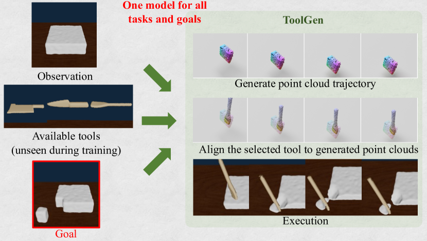
Our goal is to train a policy to solve various manipulation tasks with multiple tools, including tools that were not seen during training. We propose a novel approach, ToolGen, which learns tool-use skills via trajectory generation and sequential pose optimization. Given the scene, the goal, and a set of available tools, ToolGen first scores the different tools and selects a tool to use for the task. It then generates a point cloud of a tool in the desired initial pose, and it subsequently predicts how this generated tool would need to move to perform the task. Finally, we sequentially align the selected tool to the generated tool to extract the actions for the agent to execute. We evaluate ToolGen against several baselines in deformable object manipulation with diverse tasks, goals, and tools. Impressively, with just a single model trained across all tasks and tools, ToolGen significantly outperforms the baselines and generalizes to many novel tools. Further, ToolGen achieves this despite being trained on demonstrations from just one tool for each task. To summarize our contribution, we propose ToolGen, which represents tool use via trajectory generation. We have shown that generating a point cloud trajectory can effectively capture the essence of tool use, i.e. how the tool should be placed in relation to the dough and how it should move over time, which allows us to generalize to a variety of unseen tools and goals.
2 Related Work
Learning Generalizable Tool-use Skills: Prior work has explored training robots to perform manipulation tasks with tools. To enable generalization, some previous approaches predict intermediate “affordances” and then generate actions based on these affordances [2, 8]. For example, affordances like grasping points or functional points and be represented as key points [2, 3, 4]. More fine-grained concepts like contacts and forces [9, 10] can also be used. However, obtaining labels for these affordances can be difficult, and such affordance labels do not easily extend to more complex tasks such as deformable object manipulation as we explore in this work. Another approach is to discover affordance regions in a self-supervised way by running parameterized motion primitives [2] or affordance-conditioned policies [3, 4] in simulation. In the image space, prior works have explored training an action-conditioned video prediction model [1] for planning actions for different tools. However, the video prediction model lacks 3D structure and has difficulty representing fine-grained action trajectories. In contrast, we propose using a generated point cloud trajectory as the intermediate representation, which enables fine-grained motion planning with the generated tool.
Deformable Object Manipulation with Tools: In this work, we explore how robots can learn to use novel tools for deformable object manipulation. Prior works with deformable objects often consider using a fixed set of tools, such as a rolling pin or spatula for dough manipulation [5, 7] or knives for cutting [11, 12]. However, these works do not consider generalization to novel tools, which is the focus of this work.
3 Problem statement and assumptions
We are given point clouds of the initial observation of the scene , the goal , and a set of available tools . Our task is to select the best tool to perform the task and predict a sequence of actions to use the tool to transform the current point cloud into the goal point cloud. For training, we assume access to a set of demonstrations using a separate set of training tools . These demonstrations are of the form: , where are a set of transformations (actions) performed on the training tool which changes the initial observation into the goal configuration . The initial transformation in the sequence () brings the tool to a “reset pose.” The remaining terms () are the transformations between the subsequent tool poses in nearby timesteps, which we call “delta poses.” We manually specify distributions of the initial and goal configurations for each task. We then run trajectory optimization using a differentiable simulator to generate these demonstrations following prior works [13]. Alternatively, human demonstrations could serve as the source of these demonstrations.
4 Method
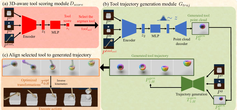
In order to teach robots how to use novel tools, we propose the following approach: our method initially selects a tool from the available set, employing a scoring network (Sec. 4.1). Then, we generate a point cloud of a desired tool and a sequence of tool actions of how this generated tool would achieve the task (Sec. 4.2). Finally, we align the selected (real) tool to each of the point clouds in the generated trajectory (Section 4.3). Finally, we move the selected tool to follow the planned trajectory to accomplish the task. Below, we describe this approach in detail, and experiments in Sec. 5 demonstrate the large benefits of this approach compared to other approaches.
4.1 3D-aware tool selection
The first step in our proposed method involves selecting the best tool for the given task. Given a set of training tools, represented as a set of point clouds, , we train a tool scoring module , which takes in a tool point cloud , the initial observation , and the goal , and it predicts a score for the tool indicating how suitable the tool is for the task. The architecture for the tool scoring module is shown in Fig. 2 (a). The module first encodes the tool points to a latent feature using a PointNet++ [14] encoder. It then encodes the concatenation of observation points and goal points to another latent feature using a separate PointNet++ encoder. These latent features are concatenated and inputted through a multi-layer perceptron (MLP) to output a score. We train the module with binary cross-entropy loss, in which the tool used in the demonstration to achieve the goal point cloud is considered as a positive example, and randomly selected tools from the training set are considered as negative examples.
For inference, we input each tool point cloud through the tool scoring module and select the tool that received the highest score among the tools available at test-time (which might be different from the tools available during training): . The selected tool is then used in subsequent steps in our method.
4.2 Representing tool-use through point cloud trajectory generation
Next, we need to estimate how the selected tool should move to perform the task. One simple approach would be to directly predict the motion of the selected tool. However, directly regressing to the tool’s pose may prove challenging, especially when attempting to regress to the tool’s orientation [15, 16, 17]. To alleviate this challenge, we instead use a generative module that generates a point cloud trajectory of a desired tool completing the task. As explained below, we will use this generated trajectory to later determine the actions of the actual tool.
We now describe the details of the point cloud generation. We first use a PointFlow-based [18] generator to produce an initial point cloud of the desired tool in the “reset pose” (i.e. the initial pose of the generated tool), which we call . The PointFlow generator conditions on a point cloud of the selected tool , the initial scene observation , and the goal . The architecture of our PointFlow-based [18] generator is shown in Fig. 2 (b) (top). It first encodes the tool points to a latent feature using a PointNet++ [14] encoder. It then encodes the concatenation of observation points and goal points to another latent feature using a separate PointNet++ encoder. These latent features are concatenated and inputted through an MLP to produce the parameters of a Gaussian distribution. We take a sample from this Gaussian distribution and input it to a PointFlow [18] decoder to produce a point cloud of a desired tool in the reset pose . During training, we condition the generator on the training tools and use the point clouds of the training tools in their reset poses as the reconstruction target in the training loss; the training data comes from the demonstration dataset described in Sec. 3. We follow PointFlow’s [18] training procedure to maximize the evidence lower bound (ELBO).
After generating the desired tool in reset pose , we then leverage an path generator to predict a sequence of transformations of how this generated tool would move to achieve the task. The architecture of the path generator is shown in Fig. 2 (b) (bottom). The path generator receives concatenated point clouds of the tool in reset pose , the initial scene observation , and the goal state . From these inputs, it then generates transformations for the tool, denoted as . We use ToolFlowNet [19] for the path generator; details can be found in Appendix A.1. This trajectory illustrates the path the generated tool would take to successfully complete the task. We train the path generator using the trajectories of the training tools as labels (from the demonstration dataset described in Sec. 3). Together, our generative module generates a trajectory of point clouds which indicates how a generated tool would move to complete the manipulation task.
4.3 Execution via sequential pose optimization
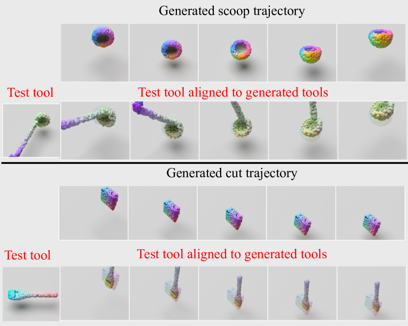
The generated point cloud trajectory from Sec. 4.2 describes the predicted trajectory for the generated tool to complete the manipulation task. However, in order to perform the manipulation task, the predicted trajectory has to be executed by a real tool, not by an imagined generated tool. In this section, we describe the optimization procedure for aligning the selected tool with the generated tool in order to extract actions for the selected tool (visualized in Fig. 2 (c) and listed in detail in Algorithm 1). Given the current observation , the selected tool , and a generated trajectory , we optimize the sequence of transformations of the selected tool to align the selected tool point cloud with each of the generated tool point clouds at each timestep.
We subdivide the optimized transformations into a reset transformation and delta poses . To compute the reset transformation, we align the selected tool to the generated tool in the first timestep . We additionally add a penalty for colliding with the observation point cloud (in our experiments, this is the dough). The loss function is given by:
| (1) |
where the first term is the Chamfer distance between the selected tool transformed by and the generated tool in reset pose, the second term is a collision penalty term computed as the Chamfer distance between the selected tool transformed by and the observation , and is a hyper-parameter balancing the two terms. The purpose of the penalty term is to penalize collisions between the tool in reset pose and the environment, though collisions will be allowed for subsequent timesteps. For optimization, we use Projected Gradient Descent, detailed in Sec. 4.4, for different initializations of and choose the one that minimizes the objective described in Eq. 1.
After optimizing the reset transformation, we then optimize the delta poses , again by aligning the selected tool to the generated tool at each timestep , with a penalty to encourage small motions. The loss function for the delta poses is given by:
| (2) | |||
The first term is the Chamfer distance between the selected tool points transformed by and the generated tool points at timestep , is a regularization function to moderate the magnitude of the translation and rotation defined by the delta poses (see Sec. 4.4 for details), and is a hyper-parameter balancing the two terms.
Finally, we apply these objectives in an optimization routine, as outlined in Algorithm 1, to align the selected tool with the generated one and produce the final trajectory for the selected tool. Subsequently, we can utilize inverse kinematics to determine the required actions for our agent to execute the task. In our case, these actions comprise the translation and angular velocities of the tool.
4.4 Implementation details
We train each module – the tool scoring module , initial point cloud generator , and path generator – separately, using a learning rate of for each module. To optimize the reset transformation, we use the quaternion representation for the orientation of the transformation, and we project the values onto a unit ball after each gradient update. Here, we use a step size of , and . For optimizing the delta poses, we use the 3-DoF Euler angles representation with a step size of , a regularization factor of , and we use the euclidean norm to regularize the translation as well as the rotation. We train a single set of modules () across a compact demonstration dataset comprised of 4 tasks (we do not train a separate network per task); for each task, we collect 200 demonstration trajectories performed with just one training tool; will demonstrate that our method will still be able to generalize to unseen tools. See Appendix B.1 for more information on our demonstration dataset.
5 Results
As shown below, we demonstrate that ToolGen is able to perform well on a variety of manipulation tasks with novel tools with just a single model trained across multiple tasks and tools. Notably, we train with demonstrations from only one training tool per task and we test on several unseen tools, demonstrating our method’s generalization abilities. We additionally evaluate ToolGen on real world observations to highlight its effectiveness when transferred to the real world.
5.1 Tasks and baselines
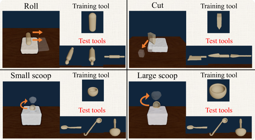
Tasks: We evaluate our method against several baselines in a soft body simulator, PlasticineLab [13]. We consider four tasks: “Roll”, “Cut”, “Small scoop” and “Large scoop”. Example configurations and their training and test tools for these tasks are depicted in Fig. 3.
In our setup, all of the tools are placed far from the dough at the start of each task, as would be the case in a normal tool-use scenario.
Metric: We specify goals as 3D point clouds of different geometric shapes. We report the normalized decrease in the Earth Mover Distance (EMD) approximated by the Sinkhorn divergence [20] computed as where are the initial and final EMD respectively. To compute the performance of each method, we evaluate 10 trajectories per task per tool and then aggregate the performance across all the tasks.
Baselines: We evaluate the following baselines with different action representations, all of which use the same tool selector as ToolGen. All of the baselines regress to reset transformations and delta poses, except for BC-E2E which predicts delta poses directly from the initial configuration without a reset transformation.
Details on the architectures of the baselines are described in Appendix B.2.
-
•
BC-E2E. End-to-end behavioral cloning that outputs a vector representing the delta poses of the tool relative to the initial tool pose. Unlike the other baselines, this baseline does not output a reset transformation.
-
•
BC-Joint. Behavioral cloning that jointly regresses to the reset transformation and subsequent delta poses from the initial tool configuration.
-
•
BC-Latent. Behavioral cloning that regresses to the reset transformation, moves the tool to the predicted reset pose, and then predict subsequent delta poses from a latent encoding of the scene with the tool in the reset pose.
- •
We examine three settings, each presenting a greater level of difficulty, detailed in Sec. 5.2, Sec. 5.3, and Sec. 5.4, respectively. We demonstrate that ToolGen is robust to these generalization challenges and maintains superior performance over the baselines. We additionally conduct ablation studies by removing the path generator of ToolGen, detailed in Appendix C.1.
5.2 Leveraging training tools at test time
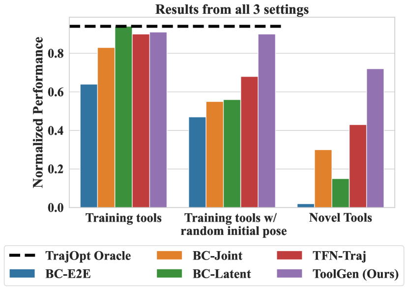
We first test the methods on a set of held out configurations using training tools. To successfully perform the manipulation, the methods need to select the right tool and then output the appropriate poses for the tool to complete the tasks. Fig. 4(a) shows the performance of all the methods. We see that most methods achieve reasonable performance. This shows that all these methods generalize reasonably well to different goal configurations given the same training tools. In contrast, BC-E2E achieves suboptimal performance on even this simple version of the task, showing the limitations of methods that do not predict a reset transformation.
5.3 Generalization to unseen initial tool poses
To simulate the fact that a tool might be in any initial configuration in the real world, we randomize the initial poses of the training tools in and rerun evaluations. From Fig. 4(a), we observe that ToolGen is the only method that is robust to this perturbation. Despite the fact that the baselines are trained with the same tools, they fail to generalize to unseen initial poses of the tool. On the other hand, ToolGen is robust to the initial configuration of the tool and receives no performance loss.
5.4 Generalization to unseen tools
| Method | Roll | Cut | Small scoop | Large Scoop | Average |
|---|---|---|---|---|---|
| BC-E2E | |||||
| BC-Joint | |||||
| BC-Latent | |||||
| TFN-Traj | |||||
| ToolGen (Ours) |
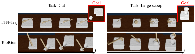
Finally, we evaluate the methods on a far more challenging scenario, in which our agents are given unseen tools. For simplicity, we evaluate each novel tool on 10 held out goals for each task and average their performances. See Fig. 3 for a visualization of the novel tools we consider. Since the novel tools also are in arbitrary initial poses, this scenario requires the method to robust to tool shapes as well as initial poses of the tool. Fig. 4(a) and Table 1 shows the quantitative results of all the methods, and Fig. 5 show examples of rollouts by ToolGen (ours) and the baseline TFN-Traj. All of the baselines fail to obtain a high performance, especially in the more challenging task of scooping (see Table 1). In contrast, ToolGen can leverage completely unseen tools in meaningful ways. This is because ToolGen leverages trajectory generation to alleviate the issues of distribution shift. It further uses a non-learned optimization procedure (gradient descent with multiple random initializations), which also does not suffer from a distribution shift. For more analysis, please see our Appendix C.1.
We show examples of the tools generated by ToolGen (top row) as well as the test tools aligned to these generated tools (bottom row) in Fig. 4(b). Overall, ToolGen achieves superior performance over the baselines in this challenging scenario of using novel tools. Remarkably, we train just a single ToolGen model across all tasks and tools, using merely one training tool per task. Despite this, ToolGen demonstrates the capacity to solve all tasks effectively when presented with novel tools.
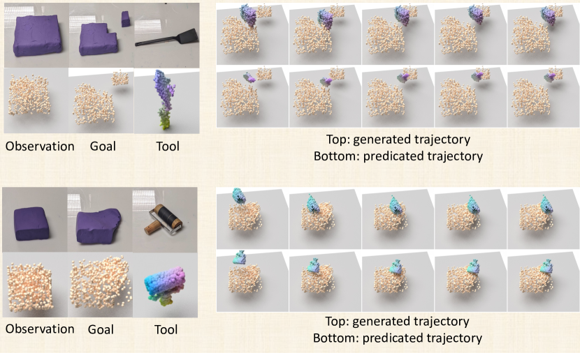
5.5 Inference on real world observations
To demonstrate the robustness of ToolGen in taking real world observations, we record point clouds from the real world and use ToolGen to predict the trajectory of the real world tool. To obtain the point clouds from the real world, we use four Azure Kinect cameras to record the initial dough and the tool point clouds. We then manually manipulate the dough to a desired shape and record the final point cloud as the goal point cloud. From there, we directly input the real world point clouds into a ToolGen model trained entirely in simulation to produce the trajectory for the real world tool. Fig. 6 includes the qualitative results of the prediction. Despite the gap in point cloud observations between sim and real, our method can predict manipulation trajectories for unseen tools in the real world. This demonstrates that ToolGen can effectively generalize to real-world observations.
6 Conclusion and limitations
Limitations: Our method has several limitations: First, our method’s execution time is considerably longer compared to that of a trained policy, due to the time needed for generating point clouds and optimizing the current tool’s poses. We anticipate that the use of faster techniques for sequential pose optimization, such as second-order methods, could speed up our method. Secondly, as our point cloud generator is trained on very limited tools, it is sometimes unable to generate accurate point clouds for novel tools and thus the alignment process could fail. A promising direction is to train on more variations of the tool to improve the generation process and make alignment easier. Further details on these failure cases can be found in Appendix C.2.
In this paper, we introduce ToolGen, a novel framework for learning generalizable tool-use skills. ToolGen uses a point cloud trajectory generation approach to represent tool use and then applies sequential pose optimization for execution. This representation circumvents the issues associated with using affordances to represent tool use, and it demonstrates superior generalization capabilities, especially when evaluating on unseen test tools, given only one tool per task for training. We applied a single ToolGen model to the manipulation of deformable objects, tackling diverse tasks, goals, and tools, and we found that ToolGen significantly outperforms the baselines and generalizes effectively to many novel tools. It is our hope that ToolGen will inspire more innovative approaches for tool use representation that enable broad ranges of generalization in the future.
References
- Xie et al. [2019] A. Xie, F. Ebert, S. Levine, and C. Finn. Improvisation through physical understanding: Using novel objects as tools with visual foresight. Robotics: Science and Systems (RSS), 2019.
- Fang et al. [2020] K. Fang, Y. Zhu, A. Garg, A. Kurenkov, V. Mehta, L. Fei-Fei, and S. Savarese. Learning task-oriented grasping for tool manipulation from simulated self-supervision. The International Journal of Robotics Research (IJRR), 2020.
- Qin et al. [2020] Z. Qin, K. Fang, Y. Zhu, L. Fei-Fei, and S. Savarese. Keto: Learning keypoint representations for tool manipulation. In IEEE International Conference on Robotics and Automation (ICRA), 2020.
- Turpin et al. [2021] D. Turpin, L. Wang, S. Tsogkas, S. Dickinson, and A. Garg. Gift: Generalizable interaction-aware functional tool affordances without labels. In Robotics: Science and Systems (RSS), 2021.
- Lin et al. [2022] X. Lin, Z. Huang, Y. Li, J. B. Tenenbaum, D. Held, and C. Gan. Diffskill: Skill abstraction from differentiable physics for deformable object manipulations with tools. International Conference on Learning Representations (ICLR), 2022.
- Qi et al. [2022] C. Qi, X. Lin, and D. Held. Learning closed-loop dough manipulation using a differentiable reset module. IEEE Robotics and Automation Letters, 7(4):9857–9864, 2022.
- Lin et al. [2022] X. Lin, C. Qi, Y. Zhang, Z. Huang, K. Fragkiadaki, Y. Li, C. Gan, and D. Held. Planning with spatial-temporal abstraction from point clouds for deformable object manipulation. In Conference on Robot Learning (CoRL), 2022.
- Zhu et al. [2015] Y. Zhu, Y. Zhao, and S. Chun Zhu. Understanding tools: Task-oriented object modeling, learning and recognition. In IEEE Conference on Computer Vision and Pattern Recognition (CVPR), 2015.
- Zhang et al. [2022] Z. Zhang, Z. Jiao, W. Wang, Y. Zhu, S.-C. Zhu, and H. Liu. Understanding physical effects for effective tool-use. IEEE Robotics and Automation Letters (R-AL), 2022.
- Wi et al. [2022] Y. Wi, A. Zeng, P. Florence, and N. Fazeli. Virdo++: Real-world, visuo-tactile dynamics and perception of deformable objects. 2022.
- Heiden et al. [2021] E. Heiden, M. Macklin, Y. Narang, D. Fox, A. Garg, and F. Ramos. Disect: A differentiable simulation engine for autonomous robotic cutting. arXiv preprint arXiv:2105.12244, 2021.
- Xu et al. [2023] Z. Xu, Z. Xian, X. Lin, C. Chi, Z. Huang, C. Gan, and S. Song. Roboninja: Learning an adaptive cutting policy for multi-material objects. Robotics: Science and Systems (RSS), 2023.
- Huang et al. [2021] Z. Huang, Y. Hu, T. Du, S. Zhou, H. Su, J. B. Tenenbaum, and C. Gan. Plasticinelab: A soft-body manipulation benchmark with differentiable physics. In International Conference on Learning Representations, 2021.
- Qi et al. [2017] C. R. Qi, L. Yi, H. Su, and L. J. Guibas. Pointnet++: Deep hierarchical feature learning on point sets in a metric space. Advances in neural information processing systems, 30, 2017.
- Peretroukhin et al. [2020] V. Peretroukhin, M. Giamou, D. M. Rosen, W. N. Greene, N. Roy, and J. Kelly. A smooth representation of belief over so (3) for deep rotation learning with uncertainty. arXiv preprint arXiv:2006.01031, 2020.
- Zhou et al. [2019] Y. Zhou, C. Barnes, J. Lu, J. Yang, and H. Li. On the continuity of rotation representations in neural networks. In Proceedings of the IEEE/CVF Conference on Computer Vision and Pattern Recognition, pages 5745–5753, 2019.
- Chen et al. [2022] J. Chen, Y. Yin, T. Birdal, B. Chen, L. J. Guibas, and H. Wang. Projective manifold gradient layer for deep rotation regression. In Proceedings of the IEEE/CVF Conference on Computer Vision and Pattern Recognition, pages 6646–6655, 2022.
- Yang et al. [2019] G. Yang, X. Huang, Z. Hao, M.-Y. Liu, S. Belongie, and B. Hariharan. Pointflow: 3d point cloud generation with continuous normalizing flows. In Proceedings of the IEEE/CVF international conference on computer vision, pages 4541–4550, 2019.
- Seita et al. [2022] D. Seita, Y. Wang, S. J. Shetty, E. Y. Li, Z. Erickson, and D. Held. Toolflownet: Robotic manipulation with tools via predicting tool flow from point clouds. In Conference on Robot Learning (CoRL), 2022.
- Séjourné et al. [2019] T. Séjourné, J. Feydy, F.-X. Vialard, A. Trouvé, and G. Peyré. Sinkhorn divergences for unbalanced optimal transport. arXiv preprint arXiv:1910.12958, 2019.
- Sorkine-Hornung and Rabinovich [2017] O. Sorkine-Hornung and M. Rabinovich. Least-squares rigid motion using svd. Computing, 1(1):1–5, 2017.
- Levinson et al. [2020] J. Levinson, C. Esteves, K. Chen, N. Snavely, A. Kanazawa, A. Rostamizadeh, and A. Makadia. An analysis of svd for deep rotation estimation. Advances in Neural Information Processing Systems, 33:22554–22565, 2020.
Appendix
Appendix A Implementation Details
A.1 Details on the path generator
The path generator starts by encoding the concatenated point clouds into a latent vector using a PointNet++ [14] encoder. This vector is then input into a ToolFlowNet [19]-based trajectory model. The trajectory model is set to a flow dimension of . The resulting output is interpreted as the tool’s flow at each time step, thereby producing delta poses via singular value decomposition [21, 22]. Finally, by utilizing this path generator with the generated tool in the reset pose , we create a point cloud trajectory . We train the path generator using the delta poses of the training tools as labels (from the demonstration dataset). At each timestep, we apply the ToolFlowNet [19] loss between the trajectory produced by and the actual trajectory of the training tool.
Appendix B Experiment Details
B.1 Details on tasks and demonstration data
| Per task | Overall | |
|---|---|---|
| # of initial configurations | 200 | 800 |
| # of target configurations | 200 | 800 |
| # of training trajectories | 180 | 720 |
| # of testing trajectories | 20 | 80 |
| # of total trajectories | 200 | 800 |
| # of total transitions |
We inherit the data generation procedure from DiffSkill [5]: first, we randomly generate initial and target configurations. The variations in these configurations include the location, shape, and size of the dough and the reset pose of the tool. We then sample a specific initial configuration and a target configuration and perform gradient-based trajectory optimization to obtain demonstration data. For each task, the demonstration data consists of all the transitions from executing the actions outputted by the trajectory optimizer, and we use a task horizon of . For each task, we perform a train/test split on the dataset and select 10 configurations in the test split for evaluating the performance for all the methods. More information about training and testing data can be found in Table 2.
B.2 Details on baselines
We provide additional details on each baseline below:
-
•
BC-E2E. End-to-end behavioral cloning that outputs a vector representing the delta poses of the tool relative to the initial tool pose. Unlike the other baselines, this baseline does not output a reset transformation. Here, we set and use delta poses in the entire trajectory (i.e. the delta poses from interpolating the initial pose and the reset pose, as well as the subsequent delta poses during manipulation) as the label to regress on. As for the architecture, it first encodes the tool points to a latent feature using a PointNet++ [14] encoder. It then encodes the concatenation of observation points and goal points to another latent feature using a separate PointNet++ encoder. These latent features are concatenated and inputted through an MLP to produce the delta poses (represented as a vector).
-
•
BC-Joint. Behavioral cloning that jointly regresses to the reset transformation and subsequent delta poses from the initial tool configuration. As for the architecture, it first encodes the tool points to a latent feature using a PointNet++ [14] encoder. It then encodes the concatenation of observation points and goal points to another latent feature using a separate PointNet++ encoder. These latent features are concatenated and inputted through an MLP to produce the reset transformation as well as delta poses.
-
•
BC-Latent. Behavioral cloning that regresses to the reset transformation, moves the tool to the predicted reset pose, and then predict subsequent delta poses from a latent encoding of the scene with the tool in the reset pose. As for the architecture, it first encodes the tool points to a latent feature using a PointNet++ [14] encoder. It then encodes the concatenation of observation points and goal points to another latent feature using a separate PointNet++ encoder. These latent features are concatenated and inputted through an MLP to produce the reset transformation. For the delta poses, we encode the concatenated point clouds of the scene (observation, goal, selected tool in the reset pose) into a latent vector using a PointNet++ encoder and then pass the latent feature though an MLP to produce the delta poses (represented as a vector).
- •
Appendix C Additional Experiments
C.1 Ablation studies
| Ablation Method | Training tools | Random initial pose | Novel tools |
|---|---|---|---|
| ToolGen Reset w/ BC-Latent | |||
| ToolGen Reset w/ TFN-Traj | |||
| ToolGen (Ours) |
We conduct an ablation study on ToolGen by modifying its point cloud generator: we only generate the initial point cloud using ToolGen and align the current tool with this point cloud to determine the current tool’s reset pose. Following this, we input the current tool at its reset pose into the delta pose predictors of BC-Latent and TFN-Traj to obtain the subsequent delta poses. This ablation provides a clear comparison between the process of directly regressing to the delta poses and the approach of using ToolGen to output delta poses. The performance gap between these two methods when using novel tools is displayed in Table 3, which underscores the significance of generalization occurring in trajectory prediction. Specifically, since these two ablations regress onto the delta poses of the training tools, they tend to overfit to the training tools, causing them to produce inaccurate trajectories when faced with out-of-distribution test tools. In contrast, ToolGen inputs the generated tool into the trajectory predictors during the generation process. The generated tool minimizes the distribution shift for the path generator and thus significantly enhances the accuracy of the resulting trajectory predictions.
C.2 Failure cases
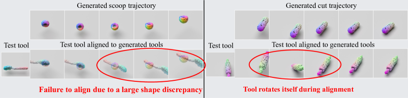
In Figure 7, we present two typical failure scenarios that occur when trying to align a novel tool with the generated tool. The first scenario, displayed on the left of Figure 7, occurs when there is a substantial disparity between the generated tool (top row) and the test tool (bottom row). In this case, the optimization process fails to meaningfully align the test tool with the generated shape in the later timesteps of the trajectory. However, this issue can be alleviated by training on more diverse tool shapes, which will create a richer shape distribution for the point cloud generator to generate.
The second type of failure results from the optimization of delta poses. The hyper-parameter regulates the balance between the actual alignment and the regularization of the rotation amount in delta poses, and can be sensitive to the task at hand. During our experiments, we found that a single value generally performs well across all tasks. However, in the "Roll" task, minor problems occurred - occasionally the tool would rotate itself when aligning with the generated tool (as shown on the right of Figure 7). This issue can be remedied by fine-tuning the optimization’s objective function and hyper-parameters for each task. For instance, by increasing the regularization parameter , we can prevent large rotations during the alignment of delta poses.
C.3 Effects of hyperparameters
| 0.01 | 0.1 | 0.5 | |
|---|---|---|---|
| 0.01 | |||
| 0.1 | |||
| 0.5 |
To investigate how sensitive ToolGen is to hyperparameters during sequential pose estimation, we vary and when optimizing for the transformations. To eliminate any stochasticity form the generation process, we only generate the trajectories once and use the same set of generated trajectories for optimization. Table 4 shows the performances of executing the trajectories that are optimized with different hyperparameters. In summary, , which penalizes collisions between the tool in reset pose and the environment, seems to have a greater effect than . This is because the alignment at the rest pose is being used to optimize the subsequent poses, and the error in optimizing the reset pose might cascade to the later process. We also observe that choosing a larger will decrease the variance in performance. This is because a larger will penalize large motions and encourage smaller and safer motions. It is worth noting that even with a large variation of these hyperparameters, ToolGen still almost always outperforms the baselines.