A Wearable Robotic Hand for Hand-over-Hand Imitation Learning
Abstract
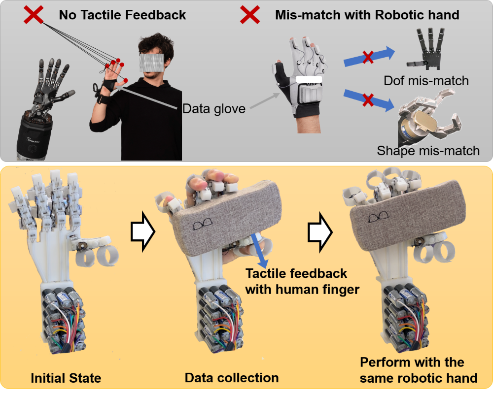
Dexterous manipulation through imitation learning has gained significant attention in robotics research. The collection of high-quality expert data holds paramount importance when using imitation learning. The existing approaches for acquiring expert data commonly involve utilizing a data glove to capture hand motion information. However, this method suffers from limitations as the collected information cannot be directly mapped to the robotic hand due to discrepancies in their degrees of freedom or structures. Furthermore, it fails to accurately capture force feedback information between the hand and objects during the demonstration process. To overcome these challenges, this paper presents a novel solution in the form of a wearable dexterous hand, namely Hand-over-hand Imitation learning wearable RObotic Hand (HIRO Hand), which integrates expert data collection and enables the implementation of dexterous operations. This HIRO Hand empowers the operator to utilize their own tactile feedback to determine appropriate force, position, and actions, resulting in more accurate imitation of the expert’s actions. We develop both non-learning and visual behavior cloning based controllers allowing HIRO Hand successfully achieves grasping and in-hand manipulation ability. More details are accessible through the link: Project website
I INTRODUCTION
Dexterous manipulation within a learning paradigm has gained significant attention in recent years [1, 2, 3, 4]. Recently, dexterous manipulation based on imitation learning has become increasingly popular [5, 6]. One of the keys to achieving dexterous manipulation through imitation learning lies in obtaining high-quality expert data. To address this, researchers have explored new paradigms using demonstration data from various sources such as data gloves [7], virtual reality [8], and videos [9]. Although these methods offer advantages in terms of data efficiency and action naturalness, they have drawbacks related to contact information feedback and mismatches between the data glove and the robotic hand. In this paper, we propose a novel approach by introducing the HIRO Hand, which integrates a dexterous hand with a data collection device. Figure 1 illustrates the hand-over-hand data collection process, where human users can utilize self-finger sensing to detect contact information. Moreover, the HIRO Hand exhibits high-performance manipulation capabilities. The contributions of this paper can be summarized as follows: 1) A novel wearable dexterous hand, integrating expert data collection and dexterous manipulation, is proposed to addresses the tactile feedback limitations when collecting expert data using data gloves. 2) Controllers based on PID and visual imitation learning were developed, respectively, and enabled the HIRO Hand to demonstrate more than 10 different grasping and manipulation tasks. 3) We develop a fully 3D-printed, 15-degree-of-freedom (DOF) dexterous hand, which is cost-effective (400 dollars) and demonstrates a repeat deviation lower than 0.14 mm. This hand is capable of handling 0.80 of human grasp types [10].
II RELATED WORK
II-A Imitation Learning with Dexterous Hands
Imitation learning (IL) is a widely utilized technique for achieving dexterous hand manipulation [9, 11, 12, 8, 13, 7, 14]. However, an outstanding challenge is the acquisition of expert data. Numerous algorithms [9, 11] have been developed to obtain data from videos, either through expert demonstrations or the internet. While internet data is cost-effective and enables fast acquisition of examples, the quality of the data acquired is usually unsatisfactory. Collecting data through virtual platforms [8, 13] or data gloves [7, 14] may improve data quality. Nonetheless, the lack of sensory feedback mechanisms (e.g., contact force, fingertip tactile) in these systems leads to imperfect demonstrations, and data collection platforms are relatively expensive. In this research, the proposed HIRO Hand leverages the contact physics of human fingers during hand-over-hand teaching to enable more precise operations, resulting in the collection of data that is both cost-effective and of high quality.
II-B Anthropomorphic Robotic Hands
Numerous dexterous anthropomorphic robotic hands have been developed. Tendon-driven mechanisms are the most similar to the human hand structure, where tendons connect to actuators located on the forearm and transmit the driving force to the robotic hand joints [15, 16, 17]. In this study, we concentrate on tendon-driven multi-DOFs hands with high dexterity[18]. The FLLEX hand [15] exhibits high impact-absorbing performance and force output. Nonetheless, the use of tendons to convey the driving force may cause a reduction in joint control precision due to their deformation. Moreover, the FLLEX hand integrates 15 servo motors, which may incur a relatively high cost. Another example of tendon-driven hands is the biomimetic robotic hands [16] reinterpret important biomechanical advantages of the human hand from a roboticist’s perspective and closely mimic the human counterpart. However, this robotic hand uses ten Dynamixel servos, which may not be able to adapt to large forces and cannot provide precise control of the finger. The Shadow Dexterous Hand, developed by Shadow Robot Company, is a high-DOFs tendon-driven robotic hand that demonstrates good manipulation performance [19]. However, the product is expensive, and the maintenance cost is high due to the complexity of the hand’s components. In general, existing tendon-driven robotic hands demonstrate a high degree of dexterity; however, their accessibility is limited by their relatively high cost. Besides, The lack of ability to collect expert data necessitates reliance on external devices or algorithm that may result in lower quality expert data. The proposed robotic hand presented offers a low-cost alternative, with high dexterity.
III ROBOT DESIGN
We present the mechanical design and the forward/inverse kinematic model of the HIRO Hand .
III-A Mechanical Design
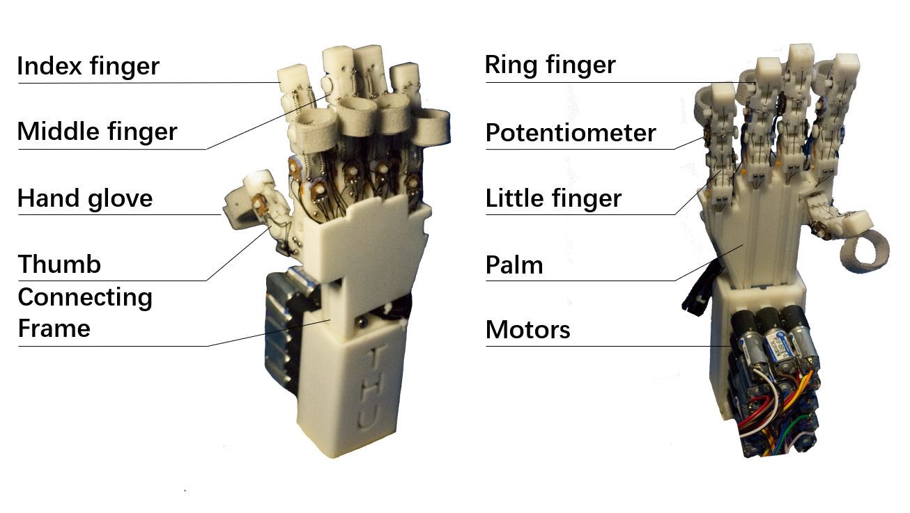
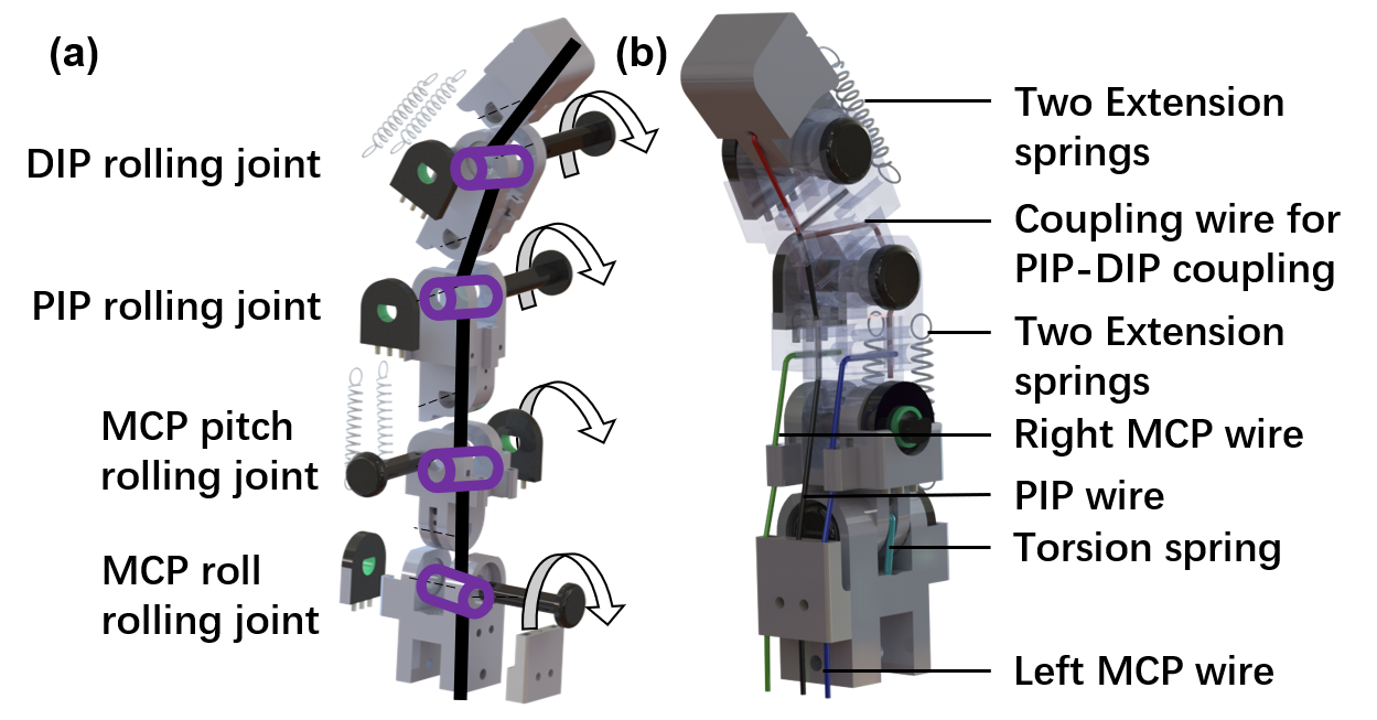
The mechanical system comprises a robotic hand, glove rings, and a driver module as shown in Fig. 2. The robotic hand is mainly 3D-printed and consists of a palm and five fingers. Each of the fingers has 3 DoFs. Thus, the HIRO Hand has 15 DoFs that can handle complex grasping or manipulation tasks. The overall design of the HIRO Hand adopts the structure of human hands [15]. Except for the thumb, each finger mimics the corresponding human finger and has four phalangeal bones: metacarpal, proximal, intermediate, and distal phalanges. Each finger also has three joints, namely the metacarpophalangeal (MCP), the proximal interphalangeal (PIP), and the distal interphalangeal (DIP) joints, which have 2, 1, and 1 DoFs respectively. The thumb shares the same design except for no intermediate phalanx. Therefore, we use the middle finger as an example in the following description. As shown in Fig. 3 (a), the 3-DoF middle finger is 56.5 mm in length and has five 3D-printed rigid components. The length of each finger is usually shorter than that of an operator’s hand, ensuring that the operator can wear the glove and operate the robotic hand smoothly. Each joint is integrated with a potentiometer that measures the real-time angle of each joint to the controller. In Fig. 3 (b), there are three groups of springs in each finger according to the distribution of finger extensors and Interosseous dorsal muscle. The first group consists of two springs that connect the DIP and PIP and the second group includes two springs connecting the PIP and MCP. Without external driving force, the springs in group one can retract the PIP and DIP joints, and the springs in group two can retract the MCP joint. Additionally, the MCP joint contains a torsion spring classified under Group 3 that possesses an inherent ability to restore the joint to its initial pose without the application of external force. The tendons that enable joint rotation comprise four drive cables: the coupled wire, the PIP wire, the right MCP wire, and the left MCP wire. Fig.4 (a) illustrates the PIP-DIP coupling wire as a red curve, which connects the PIP and DIP joints. Additionally, the PIP wire is shown as a black curve in Fig.4 (a), which facilitates the flexion motion of the PIP joint. The yellow and orange wires in 4 (b) are the left MCP and the right MCP wires that produce the MCP flexion and MCP adduction motion. The glove rings are fasteners made of nylon so that human operators may wear the robotic hand. The fastener employs both hook and loop sides, allowing for a customized level of tightness through the manipulation of the intersection degree between the two. The fastener possesses a width of 10 mm and accommodates a range of human finger sizes with inner diameters spanning from 0 mm to 25.5 mm. These attributes collectively contribute to the adaptability of the fastener, making it a suitable option for a variety of users. The driver module is composed of 15 planetary reduction motors integrated with 15 3D-printed axle sleeves, with each sleeve connecting to a driving tendon that transmits the driving force to each joint. The driving tendon, which is composed of bundled wires, has a diameter of 0.4 mm. The motor weighs 55 g and is rated for a torque of Nm. In the following section, we will detail about the bending angles of PIP, DIP, and their relationship.
III-B Joint Transmitting Model of PIP-DIP Coupling Structure
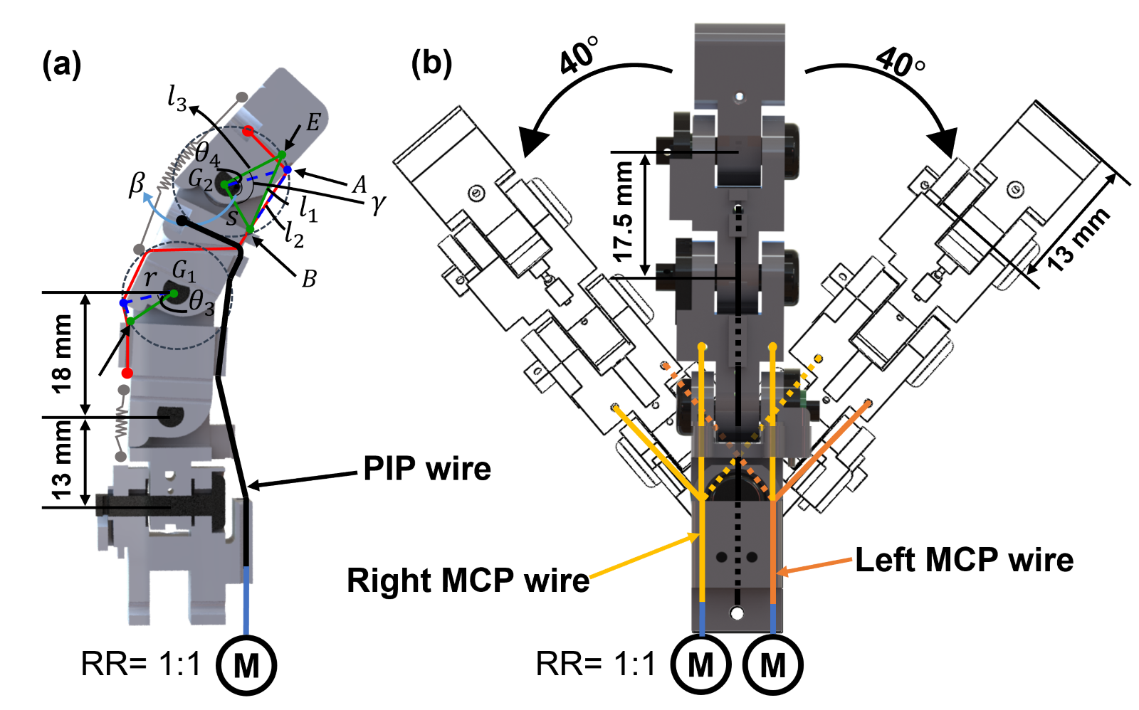
In this paragraph, we investigate the rotation angles of the PIP and DIP joints and their relationships. Specifically, we consider the scenario where the finger bends from an initial state, during which the PIP joint rotates by an angle of and the DIP joint rotates by an angle of , as shown in Fig.4 (a). The wire on the right shown in Fig. 4 (a) represents the coupling wire. The turning point of the coupling wire at the DIP is point A in the same figure. We also mark point E as the initial state of point A when the finger is fully expanded. Point B on the PIP is where the coupling wire first crosses the PIP from the DIP above, and point C is located at the edge of the PIP. Points C and D will be the same points when the mechanical finger is fully expanded. G1 and G2 denote the center points of rotation of the PIP and DIP joints, respectively. To better illustrate the kinematic and geometric properties of HIRO Hand , we define all the notations first. The distance between point C and point D after the PIP joint rotates by an angle is denoted as , while the distance between point B and point E is denoted as . The distance between point B and point A when the DIP joint is rotated by an angle of is denoted as , and the distance between point E and point is denoted as . The distance between point B and point is denoted as , while the angle between line segments A and B is denoted as and the angle between E and B is denoted as . The distance between point and point C is denoted as . Then, given the law of cosine, the length of can be expressed as equations involving and . Furthermore, is equal to the sum of and , and is the sum of and . The relationship between and is calculated as:
| (1) |
where,
III-C Kinematics And Workspace
III-C1 Forward Kinematic Analysis
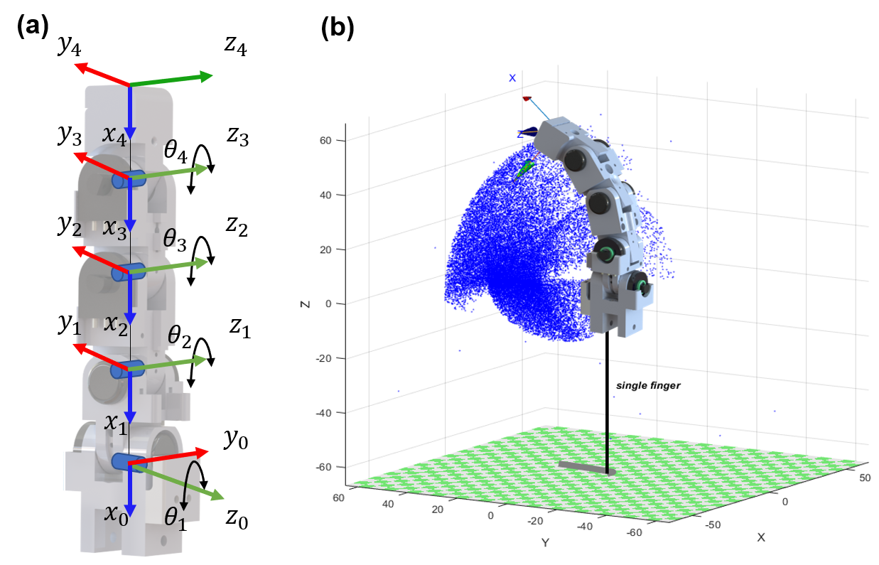
The primary objective of performing forward kinematic analysis is to compute the fingertip position of a robotic hand by leveraging the angles of its constituent joints. The kinematic model of the finger is determined through the use of the Denavit-Hartenberg (D-H) method [20]. The D-H parameters are shown in Table III-C1. The origin of the base frame, as illustrated in Fig.4 (a), is located at the MCP roll rolling joint. Building upon the aforementioned discourse on the correlation between and in the previous section, we can streamline Eq.(1) as follows:
| (2) |
Thus, according to the Denavit-Hartenberg (D-H) method, the transmission matrix , , can be calculated. In order to illustrate the application of the D-H method in a standard manner, and to elucidate the representation of theta3 in terms of theta4, can be expressed as:
| (3) |
The position and orientation of the fingertip with respect to the base coordinate system can be determined as follows:
| (4) |
| axis | d | a | axis | d | a | ||||
|---|---|---|---|---|---|---|---|---|---|
| 1 | 0 | 13 | 2 | 0 | 18 | 0 | |||
| 3 | 0 | 17.5 | 0 | 4 | 0 | 18 | 0 |
| Payload(g) | Times | Std.Deviation(mm) | Max Deviation(mm) |
|---|---|---|---|
| 600 | 108 | 0.14 | 0.32 |
| 900 | 117 | 0.08 | 0.16 |
| 1200 | 110 | 0.13 | 0.36 |
| 1500 | 100 | 0.11 | 0.26 |
As depicted in Fig. 4 (b), the workspace is computed using a Monte Carlo tree search algorithm. In the current experiment, the pitch joints of DIP, PIP, and MCP are rolled up to , while the MCP’s rolling joint is rotated to with a inclination to both the left and right sides.
III-C2 End Effector Vector
The determination of the position and orientation of a robot’s end effector is important as it interacts with the environment directly. We use end effector vector, which represents the end effector’s location and orientation in a three-dimensional space, to control the end effector. The end effector vector can be expressed as:
| (5) |
where, =18, =13,
IV Performance of The HIRO Hand
In this section, we test the performance of the HIRO Hand hand: 1) repeatability with different payloads; 2) the grasping ability; 3) the in-hand manipulation ability.
IV-A Single Finger Repeatability with a Payload
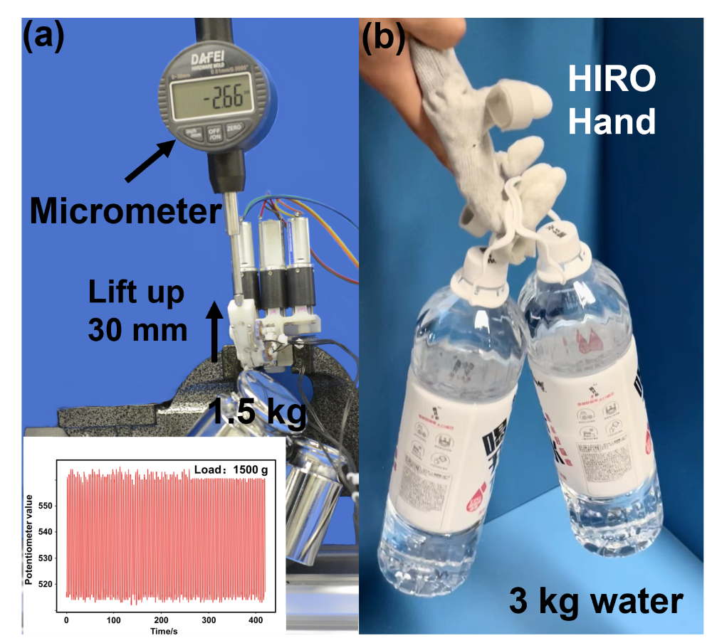
As depicted in Fig. 5 (a), a weight is attached to the fingertip, with a micrometer positioned beyond it. The weight is lifted up 30 mm and subsequently lowered to its original position within a single period. In the experiments, the finger is commanded to perform 100 periods while carrying varying payloads ranging from 500 g to 1500 g. The driving force can then be assessed. Fig. 5 (b) illustrates that a finger of HIRO Hand is lifting a 3 kg bottled water using three fingers. Table II presents the standard and maximum deviations observed under different experimental conditions, with payloads ranging from 600 g to 1500 g. The results show a single finger is capable of lifting weights exceeding 1500 g with a standard deviation of 0.11 mm and a maximum deviation of 0.26 mm across 100 lifting cycles. Additionally, Fig. 6 illustrates the potentiometer value variation over time during the repeatability experiment.
IV-B The Grasping Performance
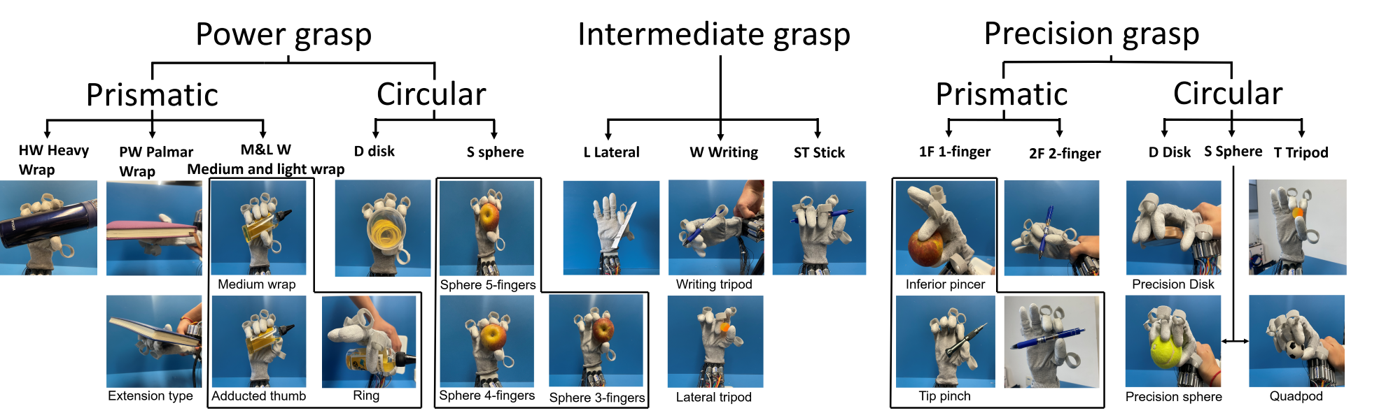
Grasping is a crucial operation for a robotic hand to perform later dexterous manipulation tasks. Grasping types are roughly categorized into three main groups: power grasps, intermediate grasps, and precision grasps. Within these categories, there are in total 28 fine-grained grasp types [10]. As demonstrated in Fig. 7, the HIRO Hand ’s grasping ability is evaluated without any external assistance, and the findings reveal that the HIRO Hand is capable of executing 21 grasp types, covering nearly 0.80 of all grasp types.
V HAND OVER HAND TEACHING RESULTS
In this section, we use both control-based and learning-based controllers to enable grasping and in-hand manipulation of objects from demonstrations using HIRO Hand.
V-A Teaching the to HIRO Hand Manipulate through PID-based Method
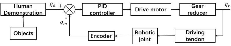
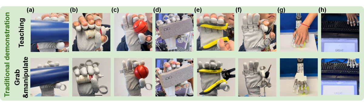
We describe both the demonstration collection and the control algorithm in this section. As shown in Fig. 8, there are two steps. The first step is that, for different objects, a human operator wears the robotic hand as a glove and performs the desired task while each joint angle position is being recorded. In the second step, a PID position controller [21] is used, and given a desired position , the robotic hand reaches the desired position. The PID controller is expressed as follows:
| (6) |
| (7) |
where represents the fifteen potentiometer values(, ). Here, denotes the desired joint angle position, denotes the feedback real-time joint angle position of each joint, and represents the PWM output command for driving the motors. The term denotes the error between the real-time joint angle and the desired joint angle, while the value of is the value of from the previous time step. To evaluate the algorithm’s performance, a series of experiments are conducted, which include grasping objects such as a cup, glue bottle, toy ball, class box, tongs, and a key, as shown in Fig.9 (a)-(e). Furthermore, the HIRO Hand is taught to rotate a tennis ball (Fig.9 (f)) and type the letter "GREAT" on a standard 433 125 30 mm keyboard (Fig. 9 (g)) without any external assistance, thereby demonstrating its advantage from multi-DOF flexibility.
V-B Teaching the HIRO Hand to Manipulate with Visual Imitation Learning
| Output shape | Activate function | Optimizer | CL | DL |
|---|---|---|---|---|
| 15 | relu | Adam | 3 | 3 |
| Name | Price | Power grasp | repeatability | Dofs |
|---|---|---|---|---|
| Shadow hand lite | 60000 | 4 | NA | 13 |
| Fllex hand lite | 60000 | NA | 0.20 | 15 |
| Ours | 400 | more than 3 | 0.14 | 15 |
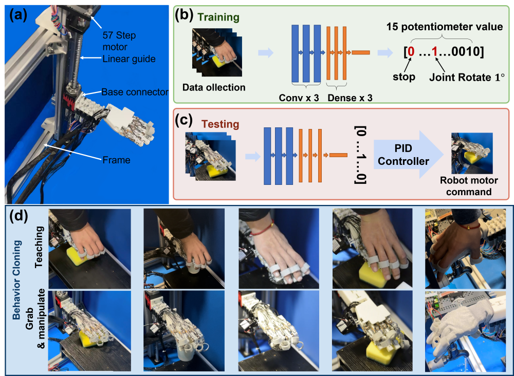
We use the widely adopted behavior cloning as our imitation learning algorithm as shown in Fig. 10 (b)-(c). The HIRO Hand learns to perform grasping or manipulation tasks purely from visual inputs. The HIRO Hand is fixed to a 1-DoF robotic arm via the base connector. The robotic arm comprises a 57mm stepper motor and a linear guide (FUYU Company) and is mounted on a steel frame, as illustrated in Fig. 10 (a). The robotic arm enables the HIRO Hand to execute unidirectional movement along the linear guide axis. The HIRO Hand is positioned above the object and lowered until the object is in contact. Throughout this process. A USB industrial camera (HSK-200W, HSK Company) is fixed to the hand and captures fifteen images per second, while the corresponding fifteen potentiometer values are recorded as binary values (0 or 1). The fifteen values correspond to the fifteen joint angles, where 0 indicates no response is needed, and 1 indicates that the joint should rotate by using a PID controller. Following that, the training process employed convolutional neural networks(CNN) [22]. More parameters of the algorithm are shown in Table. III. Each training iteration consists of 45 steps, with a batch size of 75, and a total of 45 epochs is executed. The input images have a resolution of 160320 pixels. The RGB color space of the input images is converted to the YUV color space. Following this step, Gaussian blurring is applied to reduce image noise and details. Then, the image undergoes enhanced smoothing and normalization. Moreover, we perform luminance variation-based data augmentation techniques on the image, with a range from 0.2 to 1.2. Throughout each task, we process approximately 600 data samples gathered at a frequency of 30Hz. At test time, the HIRO Hand descends from the reference position, with concurrent real-time image capture by the camera. The CNN-based robot controller makes predictions for the output potentiometer values, which are subsequently transmitted to the PID controller(). The controller then generates the requisite motor commands for the robotic system. More details about the code are accessible through the link: Code details
Fig. 10 (c) illustrates the implementation of five experiments. The first three experiments tries to grasp the "egg crate" foam (success rate: 0.60), cup (success rate: 0.67), and wire ball (success rate: 0.75), respectively. In these experiments, the objective of the HIRO Hand is to approach the target objects from a distance and perform grasping, which reflects scenarios where humans reach out to retrieve an object located some distance away. The fourth experiment involves rotating the "egg crate" foam (success rate: 1.00). Notably, the HIRO Hand commences in close proximity to the foam to facilitate direct rotation. This experiment is designed to simulate real-world scenarios where individuals need to reorient objects as part of their daily activities. The last experiment involves chained behaviors of grasping and manipulation of the faucet (success rate: 0.75). More precisely, the proposed approach requires the HIRO Hand to perform 1) sub-task 1: approaching the faucet and performing grasping, followed by 2) sub-task 2: unscrewing the faucet before reaching an end. It is worth noting that the aforementioned sub-tasks are accomplished through an end-to-end behavior cloning algorithm, which effectively showcases the HIRO Hand ’s potential to execute sequential actions in real-world scenarios based on behavior cloning. The average success rate of the five experiments is 0.722 and the results reveal that the algorithm performs satisfactorily in the aforementioned tasks.
VI CONCLUSIONS
In this paper, we present the HIRO Hand as a novel approach for data collecting and learning from human demonstrations, as well as presenting dexterous manipulation. The developed finger can exert 15N fingertip force and has a 0.14mm average repeatability of fingertip position under multiple loads from 500g to 1500g. The HIRO Hand is completely fabricated using 3D printing technology, resulting in a cost below $400. The comparison of common cable-driven robotic hands is shown in Table. IV. Additionally, both PID- and imitation learning-based robot controllers are developed. Notably, the HIRO Hand is capable of accomplishing complex tasks such as sequentially grasping and unscrewing a faucet using an off-the-shelf behavior cloning algorithm. Future work involves collecting large-scale data by wearing this glove during daily activities, integrating more sensors to capture multi-modal signals from the environment, and integrating the HIRO Hand into a robot arm to undertake more intricate tasks.
References
- [1] Henry Zhu, Abhishek Gupta, Aravind Rajeswaran, Sergey Levine, and Vikash Kumar. Dexterous manipulation with deep reinforcement learning: Efficient, general, and low-cost. In 2019 International Conference on Robotics and Automation (ICRA), pages 3651–3657, 2019.
- [2] OpenAI: Marcin Andrychowicz, Bowen Baker, Maciek Chociej, Rafal Józefowicz, Bob McGrew, Jakub Pachocki, Arthur Petron, Matthias Plappert, Glenn Powell, Alex Ray, Jonas Schneider, Szymon Sidor, Josh Tobin, Peter Welinder, Lilian Weng, and Wojciech Zaremba. Learning dexterous in-hand manipulation. The International Journal of Robotics Research, 39(1):3–20, 2020.
- [3] Yuanpei Chen, Tianhao Wu, Shengjie Wang, Xidong Feng, Jiechuan Jiang, Zongqing Lu, Stephen McAleer, Hao Dong, Song-Chun Zhu, and Yaodong Yang. Towards human-level bimanual dexterous manipulation with reinforcement learning. In S. Koyejo, S. Mohamed, A. Agarwal, D. Belgrave, K. Cho, and A. Oh, editors, Advances in Neural Information Processing Systems, volume 35, pages 5150–5163. Curran Associates, Inc., 2022.
- [4] A.M. Okamura, N. Smaby, and M.R. Cutkosky. An overview of dexterous manipulation. In Proceedings 2000 ICRA. Millennium Conference. IEEE International Conference on Robotics and Automation. Symposia Proceedings (Cat. No.00CH37065), volume 1, pages 255–262 vol.1, 2000.
- [5] Boyuan Zheng, Sunny Verma, Jianlong Zhou, Ivor W. Tsang, and Fang Chen. Imitation learning: Progress, taxonomies and challenges. IEEE Transactions on Neural Networks and Learning Systems, pages 1–16, 2022.
- [6] Sridhar Pandian Arunachalam, Sneha Silwal, Ben Evans, and Lerrel Pinto. Dexterous imitation made easy: A learning-based framework for efficient dexterous manipulation. In 2023 IEEE International Conference on Robotics and Automation (ICRA), pages 5954–5961, 2023.
- [7] Kelin Li, Digby Chappell, and Nicolas Rojas. Immersive demonstrations are the key to imitation learning, 2023.
- [8] Tianhao Zhang, Zoe McCarthy, Owen Jow, Dennis Lee, Xi Chen, Ken Goldberg, and Pieter Abbeel. Deep imitation learning for complex manipulation tasks from virtual reality teleoperation. In 2018 IEEE International Conference on Robotics and Automation (ICRA), pages 5628–5635, 2018.
- [9] Aravind Sivakumar, Kenneth Shaw, and Deepak Pathak. Robotic telekinesis: Learning a robotic hand imitator by watching humans on youtube. In Robotics: Science and Systems XVIII. Robotics: Science and Systems Foundation, 2022.
- [10] F. Cini, V. Ortenzi, P. Corke, and M. Controzzi. On the choice of grasp type and location when handing over an object. Science Robotics, 4(27):eaau9757, 2019.
- [11] Priyanka Mandikal and Kristen Grauman. Dexvip: Learning dexterous grasping with human hand pose priors from video. ArXiv, abs/2202.00164, 2022.
- [12] Shuran Song, Andy Zeng, Johnny Lee, and Thomas Funkhouser. Grasping in the wild: Learning 6dof closed-loop grasping from low-cost demonstrations. IEEE Robotics and Automation Letters, 5(3):4978–4985, 2020.
- [13] Chengshu Li, Fei Xia, Roberto Martín-Martín, Michael Lingelbach, Sanjana Srivastava, Bokui Shen, Kent Vainio, Cem Gokmen, Gokul Dharan, Tanish Jain, et al. igibson 2.0: Object-centric simulation for robot learning of everyday household tasks. arXiv preprint arXiv:2108.03272, 2021.
- [14] Kamil Kukliński, Kerstin Fischer, Ilka Marhenke, Franziska Kirstein, Maria V. aus der Wieschen, Dorthe Sølvason, Norbert Krüger, and Thiusius Rajeeth Savarimuthu. Teleoperation for learning by demonstration: Data glove versus object manipulation for intuitive robot control. In 2014 6th International Congress on Ultra Modern Telecommunications and Control Systems and Workshops (ICUMT), pages 346–351, 2014.
- [15] Yong-Jae Kim, Junsuk Yoon, and Young-Woo Sim. Fluid lubricated dexterous finger mechanism for human-like impact absorbing capability. IEEE Robotics and Automation Letters, 4(4):3971–3978, 2019.
- [16] Zhe Xu and Emanuel Todorov. Design of a highly biomimetic anthropomorphic robotic hand towards artificial limb regeneration. In 2016 IEEE International Conference on Robotics and Automation (ICRA), pages 3485–3492, 2016.
- [17] Meng Yin, Dongyang Shang, Tiantian Xu, and Xinyu Wu. Joint modeling and closed-loop control of a robotic hand driven by the tendon-sheath. IEEE Robotics and Automation Letters, 6(4):7333–7340, 2021.
- [18] Uikyum Kim, Dawoon Jung, Heeyoen Jeong, Jongwoo Park, Hyun-Mok Jung, Joono Cheong, Hyouk Choi, Hyunmin Do, and Chanhun Park. Integrated linkage-driven dexterous anthropomorphic robotic hand. Nature Communications, 12, 12 2021.
- [19] Shuang Li, Jiaxi Jiang, Philipp Ruppel, Hongzhuo Liang, Xiaojian Ma, Norman Hendrich, Fuchun Sun, and Jianwei Zhang. A mobile robot hand-arm teleoperation system by vision and imu. 2020.
- [20] A J Critchlow. Introduction to robotics. 1 1985.
- [21] Neenu Thomas and Dr P Poongodi. Position control of dc motor using genetic algorithm based pid controller. In Proceedings of the world congress on engineering, volume 2, pages 1–3. Citeseer, 2009.
- [22] Alex Krizhevsky, Ilya Sutskever, and Geoffrey E. Hinton. Imagenet classification with deep convolutional neural networks. NIPS’12, page 1097–1105, Red Hook, NY, USA, 2012. Curran Associates Inc.