A Proof of Concept for OTFS Resilience in Doubly-Selective Channels by GPU-Enabled Real-Time SDR
Abstract
Orthogonal time frequency space (OTFS) is a modulation technique which is robust against the disruptive effects of doubly-selective channels. In this paper, we perform an experimental study of OTFS by a real-time software defined radio (SDR) setup. Our SDR consists of a Graphical Processing Unit (GPU) for signal processing programmed using Sionna and TensorFlow, and Universal Software Radio Peripheral (USRP) devices for air interface. We implement a low-latency transceiver structure for OTFS and investigate its performance under various Doppler values. By comparing the performance of OTFS with Orthogonal Frequency Division Multiplexing (OFDM), we demonstrate that OTFS is highly robust against the disruptive effects of doubly-selective channels in a real-time experimental setup.
Index Terms:
OTFS, GPU, software defined radio, Sionna.I Introduction
Future communication systems should be able to support different service types and provide reliable communication over a diverse set of channels. One of the most challenging scenarios is the high-mobility scenario where conventional frequency-based transmissions like OFDM, face severe inter-carrier interference (ICI). The Doppler spread of the the time-variant channels will turn the channel into a doubly selective or doubly dispersive channel. OFDM-based transmission schemes are basically designed to mitigate the time selectivity of the channel and when it comes to a doubly selective channels their performance will degrade. In contrast, recently proposed Orthogonal Time Frequency and Space (OTFS) transmission has been shown to be resilient to delay and doppler shifts of the signal [1, 2]. In OTFS, data is modulated in the delay-doppler domain which is the same domain that we usually characterize the wireless communication channel. The interesting property of the OTFS is that localized data in delay-doppler domain can stay localized in time and frequency[1]. At the first glance it may seen in contrast with the Heisenberg uncertainty principle; but it can be shown that as long as signal generated in delay-doppler domain is quasi-periodic and have maintain certain relations between the defined regions in delay and doppler, it can be both localized in time and frequency. This property is very important and in fact enables OTFS to be theoretically resilient to selectivity in time and frequency. From practical point of view, OTFS can be implemented as a precoder in the conventional OFDM systems. These properties makes OTFS a proper candidate for high-Doppler scenarios like V2X, Non-terrestrial communications and also where there is uncertainty in the CFO like mm-Wave communications [3, 4]. In [5], the authors presents a formal analysis of OTFS’s diversity order in doubly-dispersive channels, demonstrating its performance superiority over OFDM, and confirms through simulation results that OTFS can achieve full diversity in the delay-Doppler domain.
Apart from the theoretical studies, experimental studies have also been conducted to verify the performance of OTFS in realistic environments [6, 7]. In [6], the authors use Universal Software Radio Peripheral (USRP) devices to transmit and receive OTFS signals. The Doppler channel emulation and signal processing is handled in LABView, which uses the host PC Central Processing Unit (CPU). The authors in [7] use signal generator and analyzer devices to transmit and receive an OTFS signal and use a reverberation chamber to emulate the channel effects. Most existing studies primarily focus on the BER performance comparison between OTFS and OFDM. However, there is a notable lack of discussion regarding the actual overhead of these systems. This oversight is significant as the overhead directly impacts the total throughput of the system.
In this work, we perform experimental evaluation of OTFS and its resilience in doubly-selective channels in a real-time measurement environment. We implement a full transceiver chain using Universal Software Radio Peripheral (USRP) devices as transmitter and receiver, each connected to a Graphical Processing Unit (GPU) for channel emulation and signal processing. We employ a low-complexity channel estimator and a Message-Passing (MP) algorithm for equalization to ensure low-latency processing by GPU and real-time throughput performance analysis. We emulate doubly-selective channels to analyse the performance of OTFS in a controlled environment. We compare the performance of OTFS and OFDM with various levels of time and frequency selectivity. By experimental results, we demonstrate that OTFS is more resilient against the disruptive effects of doubly-selective channels than OFDM.
II System Model
In this section, we present the OTFS modulation expressions and the transceiver architecture. Next, we describe the resource allocation, air interface, and the channel model we consider in our experiments.
II-A OTFS Modulation
We describe the OTFS modulation technique in a Single-Input Single-Output (SISO) system [1, 2, 8]. Let us denote the matrix , which is the 2D data matrix used to place data and pilot symbols in delay-Doppler domain. The dimensions and are the numbers of resource units along the delay dimension and Doppler dimension, respectively. The data matrix is first applied an inverse symplectic finite Fourier transform (ISFFT), which can be expressed as
| (1) |
where and are fast Fourier transform (FFT) matrices. A windowing is applied on the resulting signal in frequency-time domain, which can be written as
| (2) |
The resulting matrix is then passed through an OFDM demodulator and the 2D transmit signal block is obtained as
| (3) |
where and is an OFDM symbol .
When an OFDM modulator is employed to process the signal , it adds a Cyclic Prefix (CP) between the OFDM symbols to avoid inter-symbol interfence (ISI) [8]. However, a single CP at the beginning of the signal is sufficient to avoid ISI in OTFS, which makes it more efficient than OFDM in terms of overhead [11, 4]. Accordingly, the transmit signal is obtained as
| (4) |
The term is the length of CP in samples and is the CP addition matrix, where is the identity matrix of dimension and is formed by taking the last rows of . The function forms a column vector from the columns of matrix .
II-B Transceiver Architecture
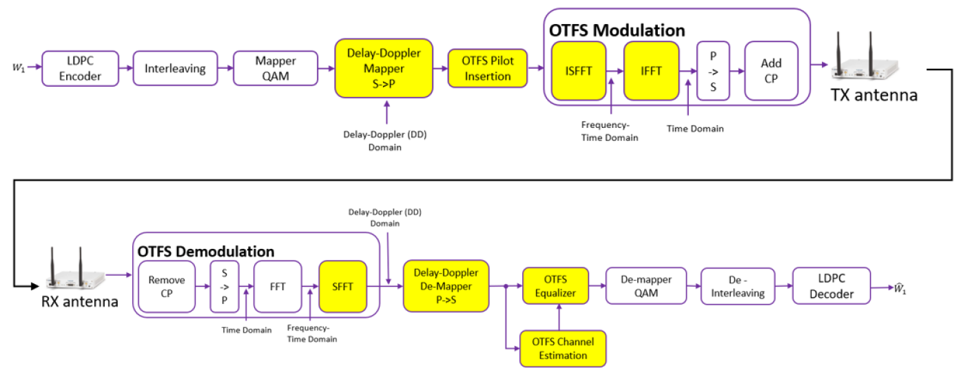
In this section, we present the implemented transceiver architecture employing OTFS modulation in a SISO system. Figure 1 shows the block diagram of the implemented architecture. At the transmitter, the input data bits are first encoded using a Low-Density Parity-Check (LDPC) encoder for Forward Error Correction (FEC). The encoded bits are then interleaved and mapped onto Quadrature Amplitude Modulation (QAM) symbols. The QAM symbols are allocated to a resource grid in the delay-Doppler domain using a resource grid mapper, followed by the insertion of pilot symbols for channel estimation and synchronization. The OTFS process involves converting the signal to the frequency-time domain using the Inverse Symplectic Finite Fourier Transform (ISFFT), converting the resulting signal to the time domain using the Inverse Fast Fourier Transform (IFFT), transforming the parallel data stream into a serial data stream through parallel-to-serial conversion, and appending a cyclic prefix to mitigate inter-symbol interference (ISI) caused by multipath propagation. Finally, the modulated signal is sent to the USRP for transmission over the air.
Upon receiving the transmitted signal, the receiver begins with the OTFS demodulation process, which involves removing the cyclic prefix, converting the serial data stream back into a parallel data stream through serial-to-parallel conversion, performing a Fast Fourier Transform (FFT) to convert the signal to the frequency-time domain, and applying a Symplectic Finite Fourier Transform (SFFT) to convert the resulting signal to the delay-Doppler domain. The signal then goes through a delay-Doppler demapper, followed by an OTFS channel estimation and equalization module. The equalized signal is then demapped using a QAM demapper, de-interleaved, and decoded with an LDPC decoder to recover the received bits.
II-C Channel Estimation and Equalization
Each OTFS packet is transmitted with a dedicated pilot to help the receiver estimate the channel. In OTFS, all symbols are spread in time and frequency, and thus, all symbols experience the same channel in delay-Doppler domain [2]. Channel estimation is performed over an embedded impulse pilot in the delay-Doppler domain. In order to avoid the interference from adjacent data symbols, a zero region is applied, where the length of this region can be set according to the channel Doppler and delay spread [9]. The output of the channel estimation is fed into the MP equalizer proposed in [10], which is slightly modified to consider the location of the pilot signal. The MP equalizer is a good match to be implemented on the GPU as it can perform the highly parallelized calculations efficiently.
II-D Resource Allocation and Air Interface
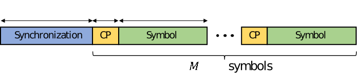
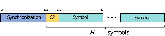
In this section, we describe the air interface used for transmission with OFDM and OTFS. Fig. 2 depicts the time slot structures for both types of transmissions. A single-carrier synchronization signal of duration seconds is appended at the start of each slot. The symbols of the synchronization signal are pulse-shaped with Root Raised Cosine (RRC) filter. For transmission with OFDM, a CP is appended before each symbol with duration and , respectively. For transmission with OTFS, a single CP appended before symbol with duration and , respectively.
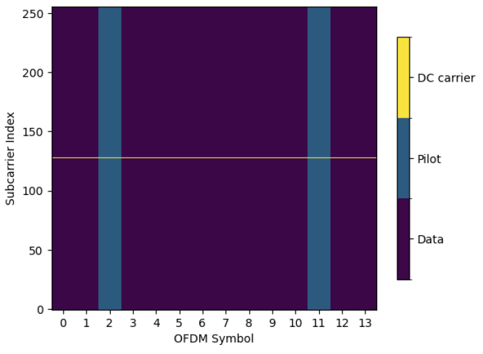
For transmissions with OFDM, a total of symbols are transmitted in a single time slot consisting of subcarriers each. Pilots are embedded in symbols over all subcarriers. An example resource grid used for OFDM transmission is given in Fig. 3 for , , and . In the considered example, OFDM symbols and are used for pilot transmission while the rest of the symbols carry data symbols in all subcarriers except the DC subcarrier.
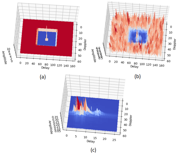
For transmissions with OTFS, a total of symbols are transmitted, obtained from a resource grid of and bins in delay-Doppler domain. A grid of and bins is left blank for pilot transmission, while the rest of the bins are used for data symbols. An example grid for OTFS transmission is given in Fig. 4 for , , , and .

II-E Channel Model
We consider doubly selective channels to model a wireless medium with multiple paths and Doppler [12]. The considered baseband channel model can be expressed in the time-delay domain as [13]:
| (5) |
where is the complex attenuation factor, is the time delay, and is the Doppler frequency shift associated with the discrete propagation path.
III Experimental Setup
In this section, we describe our testbed setup used to evaluate the OTFS transceiver architecture described in Section II-B. Fig. 5 shows the setup with a transmitter-receiver pair performing a point-to-point transmission.
III-A Hardware Components
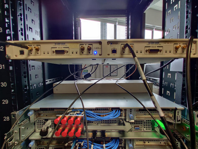
In our experimental setup, we employ two Universal Software Radio Peripheral (USRP) X310 devices, one designated as the transmitter and the other as the receiver. To ensure accurate synchronization between the transmitter and receiver, we incorporate an OctoClock CDA-2990. Both USRP X310 devices are connected to the OctoClock via SMA cables for clock synchronization, ensuring precise alignment of the transmitted and received signals.
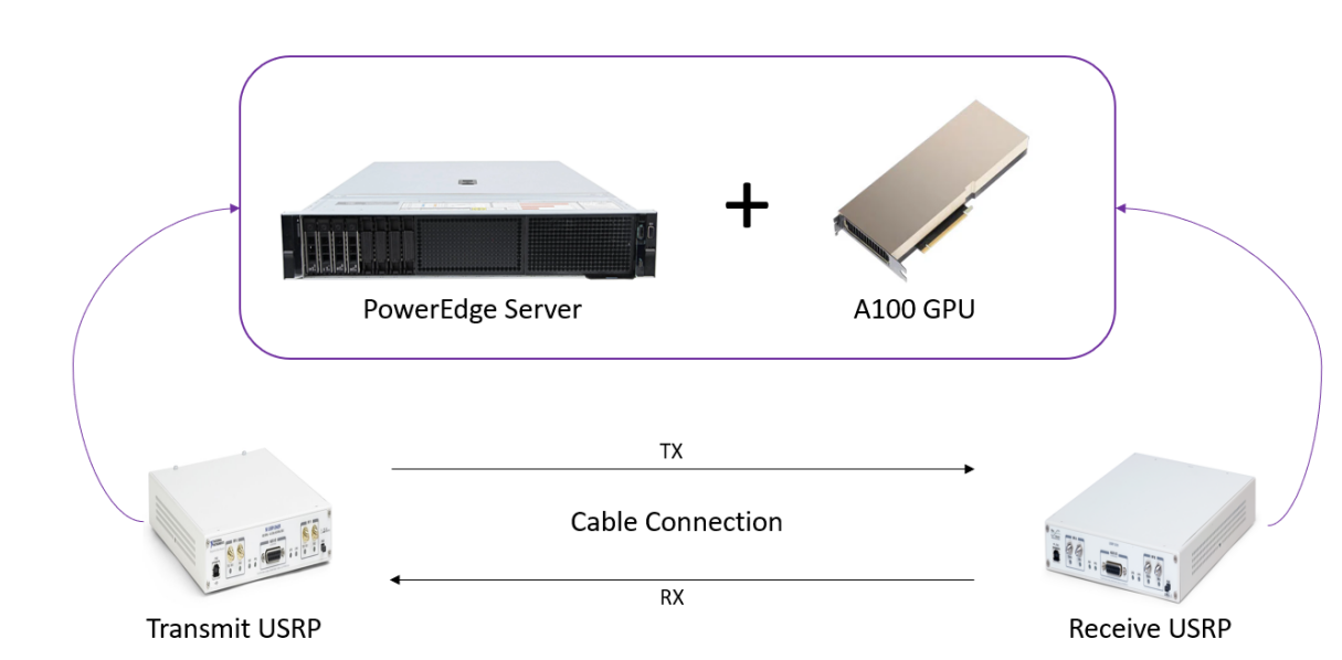
The setup is powered by a Dell PowerEdge R7525 server, equipped with two AMD EPYC 7763 64-Core processors, providing a total of 128 cores and 256 threads. These processors have a base frequency of 2.45 GHz. The system has a memory capacity of 256GB RAM and runs on Ubuntu 20.04 LTS. The USRP X310 devices are connected to the server through SFP+ ports using SFP+ cables, enabling high-speed data transfer between the TX and RX USRPs and the server, which helps to reduce the computing latency. The signal processing at both the transmitter and receiver sides is performed by an NVIDIA A100 PCIe Gen4 Graphical Processing Unit (GPU) with 80GB memory. A100 features 6,912 CUDA cores, 432 3rd generation Tensor Cores, a memory bandwidth of 2 TB/s, and a peak bandwidth of 64 GB/s, enabling faster communication between the GPU and the host system, which is essential for handling complex signal processing tasks in real-time. To further enhance parallel processing capabilities, Multiple Instance GPU (MIG) technology is employed on both the transmitter and receiver sides, enabling the application to run in parallel across multiple GPU instances and increase the GPU utilization. The setup and the connections are presented in Fig. 6.
The experiments are conducted using a cable-based connection between the transmitter and receiver USRPs. This approach allows us to eliminate the uncertainties and potential interference associated with external wireless communication, ensuring a controlled environment for the experiments. The doubly-selective channels are emulated on GPU by means of the software environment, which is detailed in the next section.
III-B Implementation Software Environment
In this section, we provide an overview of the software environment used to implement the transceiver modules on GPU and establish the communication between the GPU and the USRPs. We use Sionna to implement the blocks in our transceiver architecture [14]. Sionna is a TensorFlow based software library designed for link-level simulation of communication systems.
In our implementation, we employ several modules from the Sionna library. At the transmitter side, we use the modules RRC filter for pulse shaping of synchronization signal, FFT and IFFT for time-frequency domain conversions, CP module for mitigating inter-symbol interference, QAM module for symbol mapping LDPC module for FEC.
At the receiver end, a correlator is implemented to perform correlation with the received synchronization signal to accurately synchronize and detect the transmitted information. Following the successful correlation and synchronization, the receiver proceeds to process the received signal using Sionna modules to perform channel estimation, equalization, and decoding to recover the original transmitted data.
In order to implement new modules for OTFS modulation and demodulation, we use TensorFlow, which enables parallel computation and seamless integration of the custom modules into the Sionna library. After implementing the custom modules, we employ graph execution to further enhance the performance and adaptability of our system. This technique allows for the efficient execution of computational graphs and optimizes resource utilization, ultimately leading to a more robust and versatile transceiver architecture. To communicate with the USRP devices, we use the Universal Hardware Driver (UHD) library.
| Parameter | Value | Parameter | Value |
|---|---|---|---|
| (s) | 8.33 | ||
| (s) | 1.56 | 2 | |
| (s) | 33.3/66.6 | 15 | |
| (ms) | 1 | 330 | |
| 15 | |||
| 15 | 26 |
IV Experimental Results
In this section, we present the experimental evaluation of OTFS modulation in our setup. The parameters used in our experiments are given in Table I.
The synchronization signal is obtained by applying RRC pulse-shaping to the Primary Synchronization Signal (PSS) in 5G New Radio (NR) [15]. The PSS signal consists of symbols and the applied RRC filter has a roll-off factor of .
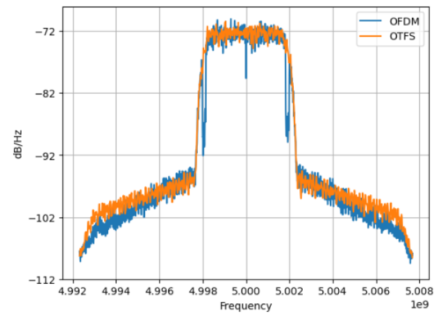
We start by comparing the generated OTFS and OFDM signals. Fig. 7 shows the comparison of Power Spectral Densities (PSDs) of OFDM and OTFS modulated signals at a carrier frequency of GHz. The plot showcases the frequency domain characteristics under the same channel conditions, with a bandwidth that is consistent across both PSDs.
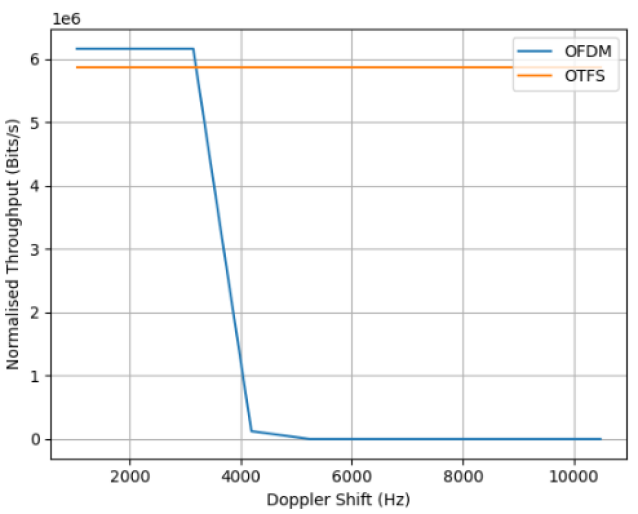
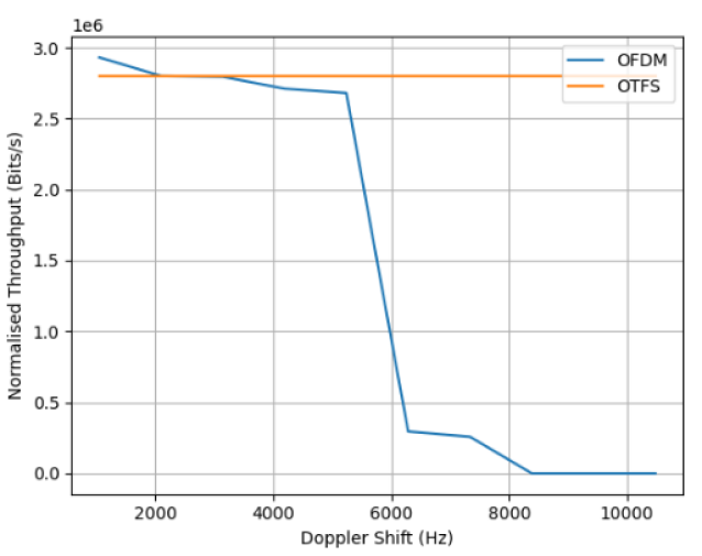
Next, we compare the throughput performance of OTFS and OFDM. We fix the modulation-coding scheme (MCS) to QPSK and a coding rate of for both transmissions. The experiments are conducted at a Signal-to-Noise Ratio (SNR) of dB to minimize the affect of noise on the resulting performance and observe the variations in performance due to doubly-selective channel effects only. We use the Tapped Delay Line (TDL) channel model [16] emulated in Sionna with taps, a delay spread of nsec and various user speed to analyse the performance.
Fig. 8 and 9 demonstrate the normalized throughput obtained using OTFS and OFDM for subcarrier spacing of kHz and kHz with respect to Doppler shift. One can see that the throughput of OFDM stays almost constant in both scenarios due to operating at high SNR up to a certain Doppler value. After a certain Doppler frequency is reached, the throughput of OFDM drops to zero as the inter-carrier interference (ICI) becomes high enough to reduce the achievable rate below what the MCS scheme can support. On the other hand, OTFS achieves a robust performance against Doppler shift owing to its delay-Doppler domain processing.
It is essential to underscore that the portion of the resource allocated to pilots and the signal, as well as the manner in which the pilot signal is embedded into the data grid, are critical factors that can influence throughput. Furthermore, the overhead introduced by the cyclic prefix (CP) can notably influence the starting point of the throughput for each scheme.
V Conclusion
In this work, we demonstrate a successful implementation and evaluation of OTFS modulation in a real-time testbed consisting of a GPU and USRPs. By leveraging the Sionna library and using TensorFlow, we implemented a low-latency transceiver architecture, which is designed to take full advantage of the OTFS scheme. By means of our experimental setup, we highlighted the potential of OTFS to provide significant performance improvements in challenging communication environments, such as those with high mobility and severe multipath conditions.
For future work, there are several possible directions to explore. Firstly, the performance of the OTFS could be further investigated under different channel conditions and scenarios, such as varying levels of interference and noise, and transitioning from cable-based to over-the-air experiments. Additionally, different OTFS algorithms and variants can be analyzed and compared to identify the most suitable options for specific communication scenarios. Moreover, the design and performance of OTFS can be investigated in a broader context of multiple access technology and multiuser communication systems. This would provide valuable insights into the applicability of OTFS in various real-world scenarios and enable the development of more efficient and robust communication strategies.
References
- [1] R. Hadani, S. Rakib, M. Tsatsanis, A. Monk, A. J. Goldsmith, A. F. Molisch, and R. Calderbank, “Orthogonal time frequency space modulation,” Proc. IEEE Wireless Commun. Netw. Conf. (WCNC), San Francisco, CA, USA, Mar. 2017, pp. 1–6.
- [2] R. Hadani, S. Rakib, S. Kons, M. Tsatsanis, A. Monk, C. Ibars, J. Delfeld, Y. Hebron, A. J. Goldsmith, A. F. Molisch, and R. Calderbank, “Orthogonal time frequency space modulation,” arXiv preprint, arXiv:1808.00519, 2018.
- [3] S. Srivastava, R. K. Singh, A. K. Jagannatham, A. Chockalingam and L. Hanzo, ”OTFS Transceiver Design and Sparse Doubly-Selective CSI Estimation in Analog and Hybrid Beamforming Aided mmWave MIMO Systems,” IEEE Trans. Wireless Commun., vol. 21, no. 12, pp. 10902-10917, Dec. 2022, doi: 10.1109/TWC.2022.3188040.
- [4] Z. Wei et al., “Orthogonal Time-Frequency Space Modulation: A Promising Next-Generation Waveform,” IEEE Wireless Commun., vol. 28, no. 4, pp. 136-144, August 2021.
- [5] G. D. Surabhi, R. M. Augustine and A. Chockalingam, ”On the Diversity of Uncoded OTFS Modulation in Doubly-Dispersive Channels,” IEEE Trans. Wireless Commun., vol. 18, no. 6, pp. 3049-3063, June 2019, doi: 10.1109/TWC.2019.2909205.
- [6] T. Thaj and E. Viterbo, “OTFS modem SDR implementation and experimental study of receiver impairment effects,” Proc. IEEE Intern. Conf. Commun. Workshops (ICC Workshops), Shanghai, China, 2019, pp. 1-6.
- [7] A. Abushattal, S. E. Zegrar, A. Yazgan, H. Arslan, “Experimental emulation for OTFS waveform RF-impairments,” Proc. IEEE Intern. Conf. Commun. Workshops (ICC Workshops), arXiv:2207.06915, 2022.
- [8] W. Shen, L. Dai, J. An, P. Fan and R. W. Heath, “Channel estimation for orthogonal time frequency space (OTFS) massive MIMO,” IEEE Trans. Sign. Proc., vol. 67, no. 16, pp. 4204-4217, Aug. 2019.
- [9] P. Raviteja, K. T. Phan and Y. Hong, ”Embedded Pilot-Aided Channel Estimation for OTFS in Delay–Doppler Channels,” IEEE Trans. Vehicular Technology, vol. 68, no. 5, pp. 4906-4917, May 2019, doi: 10.1109/TVT.2019.2906357
- [10] P. Raviteja, K. T. Phan, Y. Hong and E. Viterbo, ”Interference Cancellation and Iterative Detection for Orthogonal Time Frequency Space Modulation,” IEEE Trans. Wireless Commun., vol. 17, no. 10, pp. 6501-6515, Oct. 2018, doi: 10.1109/TWC.2018.2860011.
- [11] L. Gaudio, M. Kobayashi, G. Caire and G. Colavolpe, “On the effectiveness of OTFS for joint radar parameter estimation and communication,” IEEE Trans. Wireless Commun., vol. 19, no. 9, pp. 5951-5965, Sept. 2020.
- [12] X. Ma and G. B. Giannakis, “Maximum-diversity transmissions over doubly selective wireless channels,” IEEE Trans. Inf. Theory, vol. 49, no. 7, pp. 1832-1840, July 2003.
- [13] F. Hlawatsch and G. Matz, “Wireless communications over rapidly time-varying channels,” Elsevier/Academic Press, Amsterdam, 2011.
- [14] J. Hoydis et al., “Sionna: An open-source library for next-generation physical layer research,” arXiv:2203.11854, 2022.
- [15] “3GPP TR 38.214 v17.4.0; NR; Physical layer procedures for data,” Tech. Rep., 2022.
- [16] “3GPP TR 38.901 v17.0.0; 5G; Study on channel model for frequencies from 0.5 to 100 GHz,” Tech. Rep., 2022.