Optical Photon Simulation with Mitsuba3
Abstract
Optical photon propagation is an embarrassingly parallel operation, well suited to acceleration on GPU devices. Rendering of images employs similar techniques—for this reason, a pipeline to offload optical photon propagation from Geant4 to the industry-standard open-source renderer Mitsuba3 has been devised. With the creation of a dedicated plugin for single point multi-source emission, we find a photon propagation rate of photons per second per CPU thread using LLVM and photons per second per GPU using CUDA. This represents a speed-up of 70 on CPU and 400 on GPU over Geant4 and is competitive with other similar applications. The potential for further applications is discussed.
Keywords:
Particle Physics simulation, Ray Tracing, Cherenkov Radiation, Optical Photon, GPU computing, Multi-architecture, Rendering1 Introduction
Propagation of photons produced in High Energy Physics (HEP) simulations is computationally expensive. The propagation of photons is embarrassingly parallel, as each photon can be propagated independently from all others. For this reason, the process is well suited to technologies such as Graphical Processing Units (GPUs), High Performance Computers (HPCs), Cloud deployment or any other emerging technology well suited to embarrassingly parallel tasks.
To this end, we focus on the exploration of rendering technologies often used in animated movies. The processes employed rely on the same underlying principle—propagation of photons through a scene, which encompasses objects of interest and any other objects within the scene to be rendered, then rendering of optical photons using a camera or detection plane. This paper explores the use of one such renderer, Mitsuba3 Mitsuba3 , in the context of particle physics optical photon simulation. We present a prototype workflow for the incorporation of Mitsuba3 within the Geant4 Agostinelli:2002hh ; Allison:2006ve framework, the standard for the interaction of particles with matter in HEP. The workflow is demonstrated in the context of the simulation of a Ring Imaging Cherenkov (RICH) Detector, specifically modelled after those used by the LHCb experimentLi:2023ocy . These detectors are tasked with the generation and detection of Cherenkov photons, which are emitted by charged particles that traverse a medium at a speed greater than the phase velocity of light in the medium for use in particle identification, and are therefore key ingredients to many experimental apparatuses.
The paper is organised as follows: Section 2 presents a summary of the features of Mitsuba3, including the key features necessary to exploit multiple architectures. Section 3 discusses the key concepts behind the propagation of Cherenkov radiation within particle physics detectors, including the generation of photons in Geant4 and the modelling of quantum efficiencies of the detectors. Section 4 presents the prototype workflow on which this work is based, with Section 4.1 dedicated to the translation of geometries from Geant4 to the Mitsuba3 renderer, Section 4.2 defining the implementation of a custom photon emitter in Mitsuba3. Section 5 shows the physics validation of Mitsuba3 based photon propagation with that of Geant4, including a comparison of timing. Section 6 presents an in-depth discussion of the results, and finally conclusions and future work are presented in Section 7.
2 Summary of Key Features of Mitsuba3
2.1 Mitsuba3 Variants
Mitsuba3 Mitsuba3 is a physics-based renderer, relying on just-in-time (JIT) compilation through the use of the DrJit Jakob2020DrJit engine to generate optimised kernels. Mitsuba3 natively supports rendering on multiple platforms through the use of so-called variants, which configures the JIT compilation of Mitsuba3 on which platform to use. Specifically, Mitsuba3 supports the use of NVIDIA’s Compute Unified Device Architecture (CUDA)cuda and NVIDIA’s OptiX optix engine for processing on NVIDIA GPUs. Parallel processed ray-tracing on Central Processing Units (CPUs) is supported using LLVM LLVM:CGO04 and Intel Embree Wald:2014:EKF:2601097.2601199 ; finally serial operations is enabled via use of the scalar variant, which requires no JIT compilation. As the code supports many different architectures, the design of custom functions following the Mitsuba3 conventions enables the simultaneous development for multiple different platforms.
In addition to computational platform, variants are used to select the method by which differing wavelengths are treated during rendering. Mitsuba3 can represent wavelengths in several modes of interest, RGB and mono. In ray-based rendering tasks, it is often infeasible to represent the visible spectrum of light as a continuum of separately coloured rays. Typically, coloured images are represented by three colour channels, Red, Green and Blue (RGB). In this representation, each channel’s value corresponds to the intensity of its respective colour component, e.g. how much red, green or blue is present in the pixel, allowing control over the colour composition of each pixel. Therefore by binning the visible spectrum into low, mid and high frequency ranges, colour images can be generated using three rays per photon. Mitsuba3 facilitates this wavelength treatment through RGB variants such as llvm_rgb and cuda_rgb. The mono variants are a simplification of RGB treatment, otherwise known as the intensity treatment, where the wavelength of photons is ignored and the pixel values are represented by a single channel creating a grey scale image. These are selected using the mono variants such as llvm_mono and cuda_mono.
3 Simulation of Cherenkov Photons—propagation and detection
It is well known that when a charged particle passes through a medium at a speed faster than the phase velocity of light within the medium, Cherenkov radiation is produced. The radiation is produced at an angle relative to the charged particle’s path, where , is the velocity of the particle relative to the speed of light in vacuum and is the refractive index of the medium. The angle is independent of azimuthal angle with respect to the charged particle’s velocity. When combined with momentum measurements, the reconstruction of the angle of Cherenkov radiation originating from a charged track allows for particle identification. The Geant4 toolkit is able to produce Cherenkov radiation; For this reason, we do not explore the generation of Cherenkov Radiation by Mitsuba3 itself, but rather treat the emitted Cherenkov photons as input to the ray tracing provided by Mitsuba3.
Detection of Cherenkov photons is normally performed by either photomultipliers (PMTs), or similar technologies, and may include the reflection of the photons from a set of mirrors or surfaces. As these technologies also have a response that is dependent on photon wavelength, the modelling of the wavelength of photons is extremely important.
4 Prototype workflow
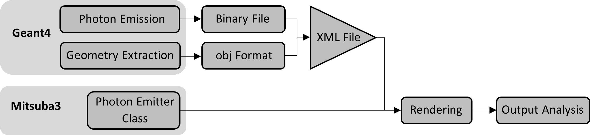
A prototype workflow was designed to aid in the transition to a fully-fledged Geant4 workflow and to enable simultaneous developments at all levels. This is illustrated in Figure 1. Each part of the workflow was designed with a memory-resident intermediate implementation in mind, allowing for intermediate file writing to be removed when each step is finished. We enumerate the individual elements of the workflow in the subsequent sections.
4.1 Translation of Geometry between Geant4 and Mitsuba3
It is necessary to transform the geometry of a RICH detector from Geant4 GDML format into a format suitable for rendering in Mitsuba3. First, the geometry is visualised within FreeCAD freecad . The geometry was simplified by removing the detector casing and related components including windows, the remaining mirrors and detector plane were grouped into OBJ files, and incorporated into an XML format file which is readable by Mitsuba3. Each stage of the process introduces its own set of considerations, and the techniques and strategies adopted to address these are discussed in the following.
FreeCAD is an open-source 3D computer-aided design (CAD) platform and is frequently used for creating, manipulating, and analysing 3D models. However, FreeCAD does not naively support the GDML format so the open-source FreeCAD plugin CAD_GDMLcad_gdml was used. This plugin serves as an effective intermediary, facilitating the interaction between the GDML input file and FreeCAD’s visualisation interface.
With this a simplified model of the RICH geometry was created as shown in Figure 2.
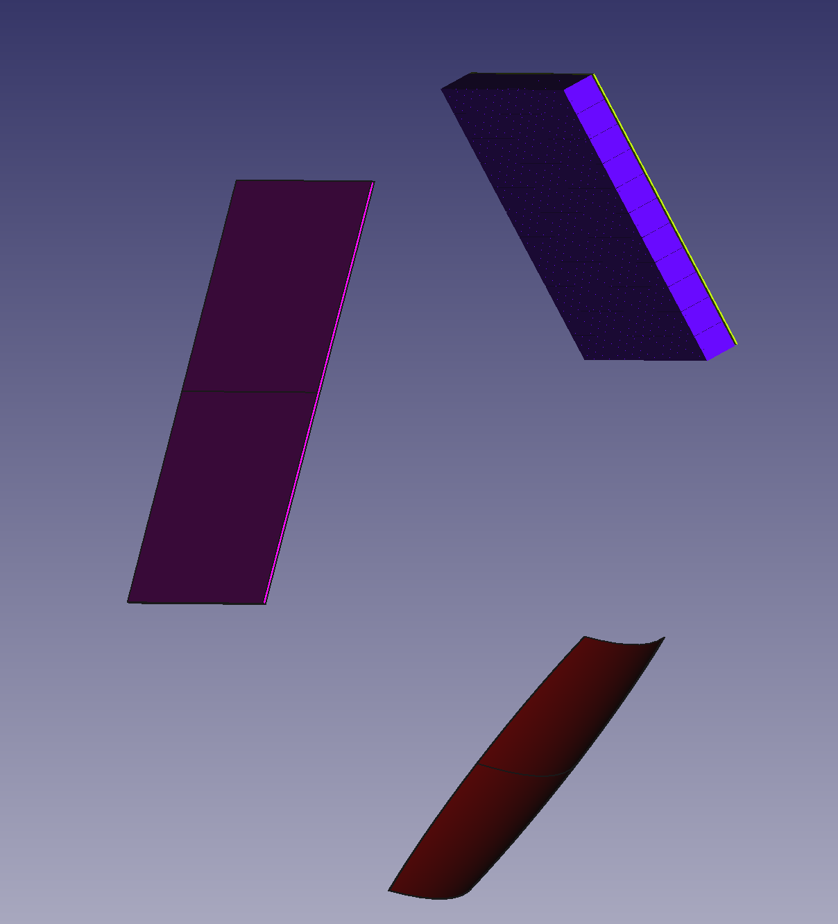
The models corresponding to the aforementioned components are exported as a pair of distinct OBJ files: the first incorporates both mirrors as a unified entity, while the second represents the detector. This strategy is adopted for two primary reasons: initially, treating the mirrors as a unified entity negates the requirement for subsequent angular modifications; furthermore, the mirrors are fabricated from identical material, facilitating the usage of a shared Bidirectional Scattering Distribution Function (BSDF). The BSDF, one of the Mitsuba3 plugins, characterises the surface materials of the objects and simulates the interaction of light with different surfaces. Conversely, the detector elements, composed of a different material, are best used when separated from the mirrors.
For the transformation of objects from FreeCAD to OBJ files, an embedded mesh generation method Mefisto is used to give a high resolution model, without compromising on approximations. The operation of this method is governed by a singular parameter, the maximum edge length. This parameter limits the edge lengths of individual triangles or polygons generated during the meshing phase. In the present instance, a maximum edge length of 5 mm is selected.
Upon integrating the OBJ files into the XML file for rendering in Mitsuba3, it is important that the coordinate systems, interrelated positions and scale of the models remain comparable to those in the GDML file. Consequently, additional model transformations within the XML file are not necessary.
We note that other options for simplification of the geometry are possible—for instance exporting only a single sub-detector to a Geant4 parallel world, followed by exporting of this world to an individual GDML file adequately removes many steps. Finally, the use of other tools, such as pyg4ometry WALKER2022108228 allow the conversion to OBJ formats in a single script. Implementation of these options is beyond the scope of this paper.
4.2 Photon Emitter
In Mitsuba3, the emitter plugins are used to initiate light rays. The spot light emitter (spot) is the closest available emitter that represents the behaviour of a photon. This plugin produces a conical light with linear falloff, governed by the cutoff_angle parameter that restricts the light emission within a specified angular range. Ideally, for photon propagation, it should be possible to represent a single photon by sufficiently minimising the cutoff_angle of a solitary (spot) emitter.
However, as the spot light emitter emits a cone shape light, regardless of the value of the parameter cutoff_angle, the size of the spot increases and its brightness decreases as the light path length increases, insufficient for the representation of single photons. Furthermore, as each spot emitter can only represent a single photon, many are needed to represent the emission of Cherenkov radiation over a charged particle’s trajectory within the radiator. The DrJit compiler creates a separate C++ object for each emitter. As such large simulations containing millions of photons can easily surpass a GPU’s global memory capacity, this approach can result in slow compilation speeds and rendering failures. This representation of photons and the significant memory usage associated with it meant using a single (spot) emitter to represent one photon is not a viable option.
To rectify these issues the photon_emitter has been developed as a custom emitter by modifying the (spot) emitter. This new emitter initiates multiple light rays by taking a vector input of initial positions and momenta read from a binary format file or Numpy array. Furthermore we set the local_dir parameter in the sample_ray function to a constant thus fixing the emitter’s orientation. The falloff_curve parameter in the photon_emitter is set to unity to ensure constant intensity. Given that only one light ray is required per emission, the concept of the cutoff_angle parameter becomes irrelevant and has been removed. As the photon_emitter can initiate every photon in a simulation with a single instantiation, the memory footprint of kernel generated by DrJit is reduced substantially, from gigabytes to kilobytes. Moreover, for large simulations containing millions of photons, the compilation time was reduced from hours to seconds.
4.3 Modelling of Quantum Efficiency
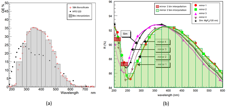
The efficiency of detection of Cherenkov photons relies on the intrinsic efficiency of the photon detectors in question and must be accounted for. In the case of the simplified RICH detector, one must consider the efficiency of the Multi-Anode Photo Multiplier Tube (MaPMT) detectors Hamamatsu and the reflectivity of the mirrors, which are wavelength dependent. Furthermore, as computational expense is dependent on the number of photons, it is advantageous to apply any quantum efficiency and reflectivity effects prior to propagation and discard the associated photons. This is justified, as any discarded photons would not be detected. Figure 3(a) describes the quantum efficiency of the detector as enumerated in Ref. LHCB_TDR_014 , which peaks at around , due to the Borosilicate window’s refractive index variations in the to region. Implementation of the efficiency was performed by transforming the measured efficiencies into histograms of bin width. The reflectivity of the mirrors, given in Figure 3(b) vary between and between and . Subsequent estimation of the reflectivity was performed in a similar fashion to the efficiency, utilising bins of . For each photon, with its specific wavelength, an accept-reject algorithm was used to model the three efficiencies before propagation. As described in section 2, this approach is only valid when using the mono variants, which are inherently faster than the variants that render multiple wavelengths.
4.4 Translation to global coordinate systems
In Mitsuba3, detection is achieved using the camera and film plugins to sample the propagated rays. The detector plane in the simplified RICH geometry measured , which defined the size of the film. The camera was placed at a distance of , facing the centre of the detector. The field of view was empirically set to to match the size of the detector. These values where determined empirically by matching the radii of the Cherenkov rings. The bitmap output was translated into a Numpy detection matrix. The mono variants created a two-dimensional array of intensities at each pixel ranging between and . A temporary method was used to set an empirical threshold of intensity of in local units to keep the same number of hits as rays propagated, only accepting values above this threshold. This solution is not viable but enabled checking the implementation of the geometry. The position of each cell passing this threshold was recorded as a photons hit; these were 2D coordinates relative to the bottom left corner of the detector plane.
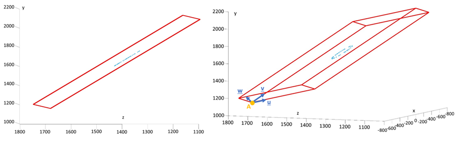
Detected photons in Geant4 are referred to as hits and are represented as coordinates relative to an origin defined in the geometry in this case, the centre of the RICH detector. In Figure 4 we see the hits as recorded in Geant4 relative to the detector volume. There is an offset due to the simplification of geometry, in Geant4 detection occurs at the back side of the MaPMTs whereas for the simplified geometry used in Mitsuba3 detection occurs at the front side of the detector volume shown in red in Figure 4. The hits in Geant4 were projected onto the surface of the detector volume creating two-dimensional coordinates allowing for direct comparison to Mitsuba3, as illustrated in Figure 4. This issue is easily remedied by taking the final position of the rays as global coordinates, but requires a change to the underlying Mitsuba3 output.
5 Results
5.1 Comparison of Cherenkov Rings
Simulations of Cherenkov photons using the simplified RICH geometry were first performed in Geant4 using a particle. The origin and momenta of the emitted Cherenkov photons were output in binary format and used as input to Mitsuba3, following the described pipeline.
Figure 5(a) shows the path of the and of the emitted Cherenkov photons in Geant4. At the bottom are the origins of the photons. At the bottom on the right, a smaller green cone can be seen emerging from the particle’s path behind the spherical mirror due to emission past the first mirror. Figure 5(b) shows the corresponding scene in Mitsuba3. For the sake of visualisation, spot emitters were used to show the end of the trajectory of the hits. At the top, a ring of light can be seen. A green wall was added on the right of the scene to show a second ring of light in the bottom right corner, behind the spherical mirror due to photons emitted by the after passing through it.
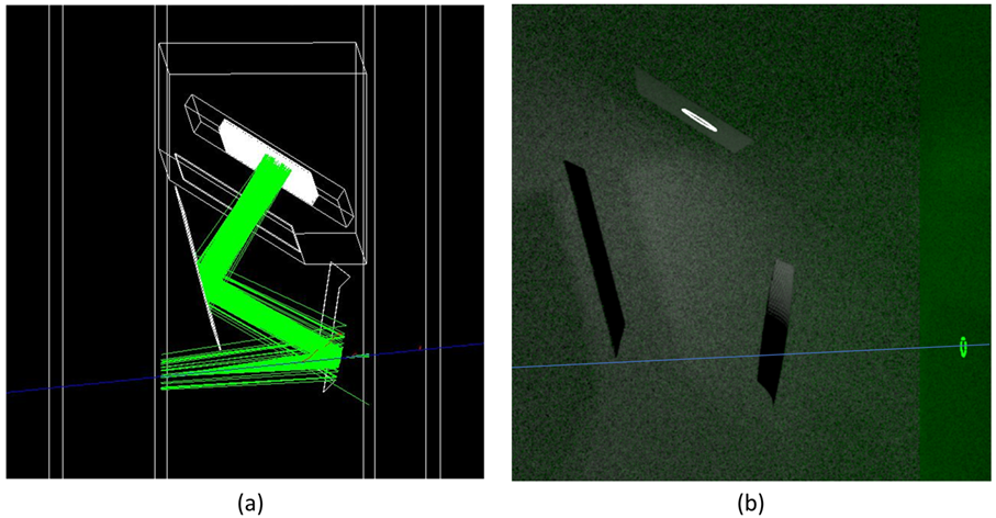
Both scenes demonstrate identical light behaviours. The ring of light forming behind the spherical mirror supported the good calibration of the objects in Mitsuba3.
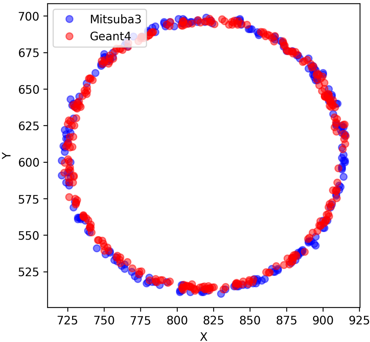
Hits were simulated in both software including the quantum efficiency and reflectivity and are shown in Figure 6. The Cherenkov rings returned by Geant4 and Mitsuba3 are comparable, exhibiting similar radii, however, the absolute positions differ. Results are discussed later in section 6.
5.2 Timing
Both the wavelength treatment and parallelisation implementation are selected at run-time using variants. This study tested and compared four variants, llvm_mono,
llvm_rgb, cuda_mono, and cuda_rgb, which are described in Section 2.1. These variants were chosen to test both relative speed-up against Geant4 for CPU and GPU propagation; as well as for wavelength treatment as these will become important in the future.
The CPU used in testing was an Intel(R) Xeon(R) Silver 4210R 2.40GHz with 20 cores, each timing simulation was executed with 1,2,4,8,16 and 20 threads and repeated three times to eliminate outliers. Testing on GPU was performed on a NVIDIA Tesla T4 with 2560 threads, a base clock of 585 MHz (1590 MHz boost clock) and 40 Ray Tracing (RT) cores.
Mitsuba3 has in built timing reports which are generated at run-time for a variety of rendering stages. Timings were confirmed using the NVIDIA NSight tools nvidia_nsight . Through investigation of the timing reports, it was determined that there were three areas of computation expense, parsing of the XML file, initialisation of the kernel which includes the DrJit compilation and rendering of the scene.
6 Discussion
In Figure 6, the overlap of the rings showed that the centre of both fell in the same position. This confirms the comparable behavior of both Geant4 and Mitsuba3 and the accurate translation of the geometry. The initial coordinates of the photons were directly exported from Geant4 to Mitsuba3; therefore, the similarity of the ring sizes verifies that the coordinate system in Mitsuba3 corresponds to that of Geant4. Finally, corroborating again the correct geometry, the comparable radii are the key result of the simulation. The Cherenkov angle is calculated from the radius of the ring and thus the speed of the charged particle can be identified. Both rings will give the same charged particle’s speed and demonstrate Mitsuba3’s potential for future implementation.
Two issues arose from Figure 6. The exact position of the hits did not correspond, and the radius of the ring in Mitsuba3 seemed slightly larger than that of Geant4. The clash in the position of the hits came from the random filtering of the photons described in section 4.3 and the method used to identify hits on the detector described in section 4.1. The threshold was set to to identify as many rays as emitted after filtering as possible. Some pixels in the detector were brighter than the implemented threshold due to signal leakage to neighboring pixels. Some other photons fell between pixels and gave a maximum pixel intensity value of less the threshold. The radii mismatch is due to the discussed scale mismatch. Photons in Geant4 and Mitsuba3 did not effectively hit the same surface (see Figure 4) and the projection of the hits onto the surface introduced errors. The recording of final positions in Mitsuba3 was made through a camera with a field of view determined with approximations. A variation of a tenth of degree in the field of view could offset the position of the hits. Finally, the pixel hits were detected, and not their exact positions, providing an accuracy of at best - the size of a pixel on the film. These issues can be mitigated by the output of individual global hit positions as opposed to direct detector response.
The Geant4 simulation used for comparison with
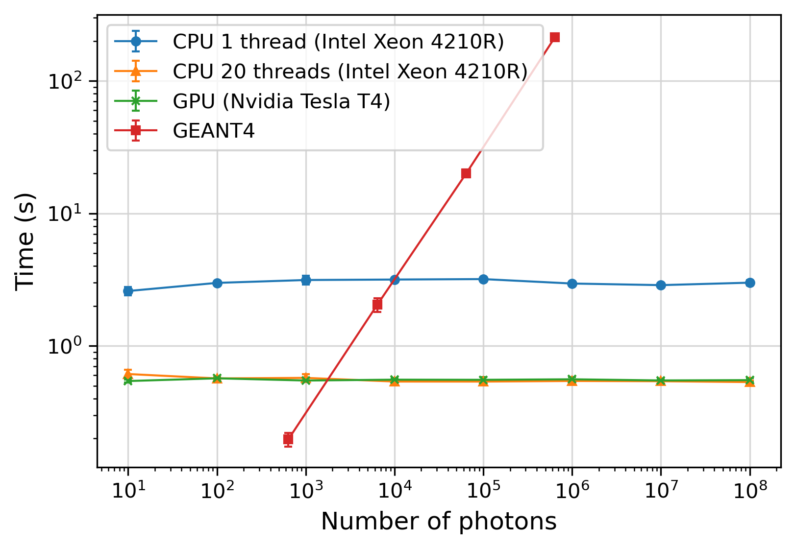
Mitsuba3 was run on a single thread on the CPU, and hence, was not parallelised. The time taken to propagate photons was measured for simulations that produced to photons, in steps of factors of 10. The scaling profile of Mitsuba3 on different architectures and that of Geant4 are presented in Figure 7. The first observation is that, contrary to the Geant4 simulation, the Mitsuba3 implementation does not scale with the number of photons. This indicates that there is a step in the rendering process that is the same over all of the different variations and which dominates the total time. This is known to be the production of the images but can be improved by writing the global coordinates of the photons, directly bypassing this step. Furthermore, this is independent of the architecture since both the CPU and the GPU exhibit this behaviour.
The second observation is that Mitsuba3 outperforms Geant4 when simulating photons on the GPU or on the CPU at 20 cores, and when propagating photons on the CPU with a single thread. Beyond these thresholds, Mitsuba3 then becomes increasingly faster than Geant4. For example, when considering the maximum number of photons simulated by Geant4, i.e. , Mitsuba3 is approximately 70 times faster on the CPU at a single thread and 400 times faster on both the GPU and CPU at 20 threads. Another way of quantifying the performance of the two pipelines is by calculating the photo propagation rate i.e. the number of photons propagated per second. The Mitsuba3 framework is capable of rendering about photons per second on both the GPU and on the CPU at 20 threads, and photons per second on the single-threaded CPU. By contrast, the Geant4 simulation is capable of propagating up to photons per second. Therefore, for a workload greater than the threshold values, offloading the propagation of Cherenkov photons to the Mitsuba3 pipeline will be significantly more efficient than simulating them using Geant4.
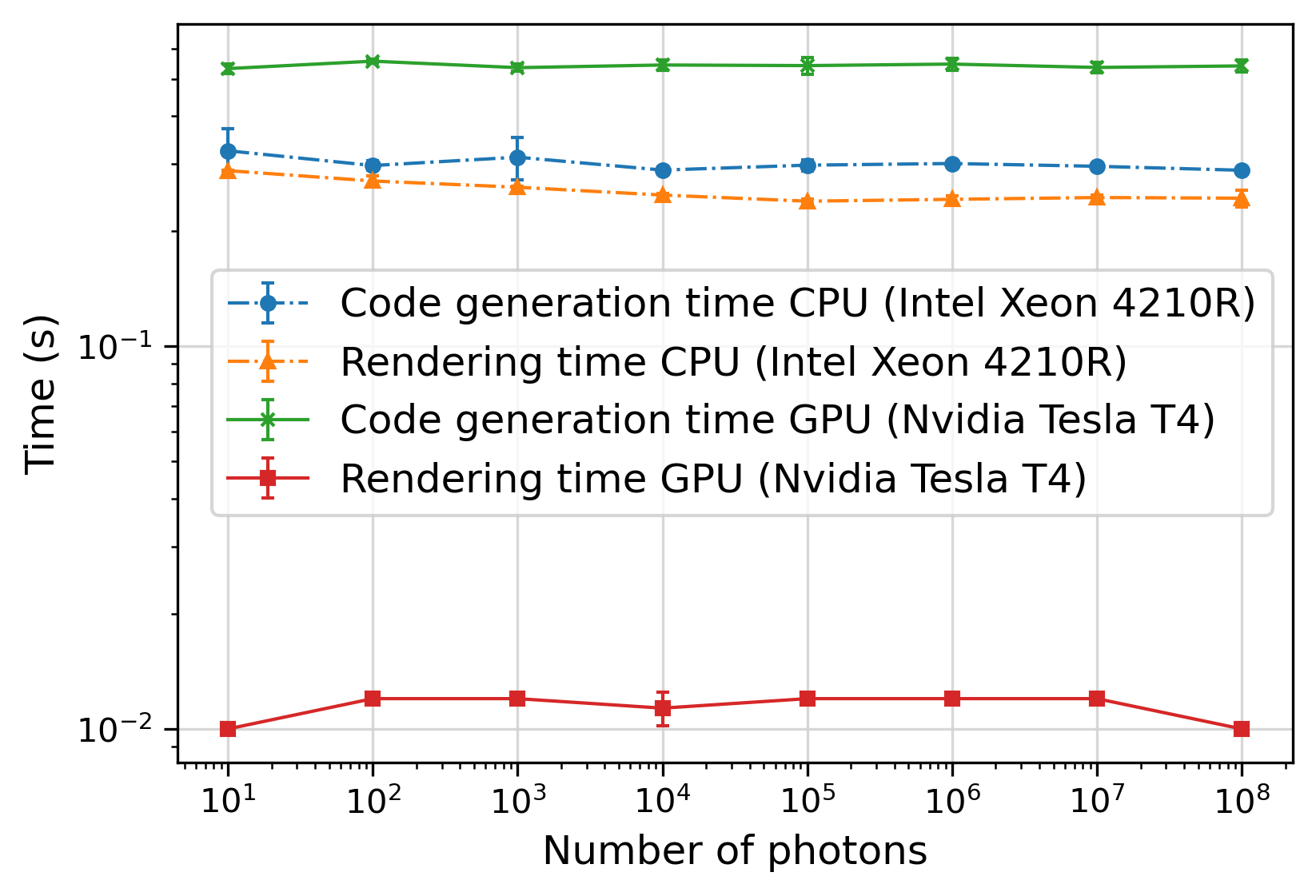
Finally, the third notable feature of this plot is the similar performance between the GPU and the CPU at 20 threads. This is odd behavior at first sight due to the fact that the NVIDIA GPU has a greater number of cores compared to the Intel CPU and that, in general, GPUs are better suited for ray tracing. Breaking down the simulation time into the code generation time and rendering time separately, as shown in Figure 8, reveals that when running Mitsuba3 on the GPU the code generation time significantly outweighs the rendering time. On the other hand, when running Mitsuba3 on the CPU at 20 cores both times are comparable. Isolating the rendering time, the GPU is times faster than the CPU. Therefore, optimising the code generation when using the GPU can significantly improve Mitsuba3’s performance, thereby further reducing the threshold number of photons required to outperform Geant4 on that architecture.
7 Conclusion and future work
A successful prototype workflow offloading Cherenkov photon propagation from Geant4 to Mitsuba3 has been implemented. A light source analogue to a photon consisting of a single ray with infinitesimal width, in a single direction, and without decaying intensity was successfully created in Mitsuba3. The intrinsic efficiencies of each object contained in the simplified LHCb RICH detector were reproduced and the detection of photons propagated with Mitsuba3 was successful. The comparison of the outputs confirmed the correct implementation of a simplified RICH geometry and the accurate propagation of the photons within that geometry. The timing study showed that, up to photons, the simulation time in Mitsuba3 does not scale with the number of photons. Above photons, Mitsuba3 is significantly faster than Geant4. The simulation in Mitsuba3 is not yet ready to be integrated into Geant4 but, with further development, this is expected to be feasible and to yield significant performance gains.
Mitsuba3 proved its potential for physics experiments involving light propagation. However, the graphical results are not yet accurate enough for the substitution of Geant4. The transition to memory-resident objects is essential. Such a change will allow the output method to return the global coordinates of the hits. In a similar fashion to what was done for the photon_emitter in the source code, a new BSDF class should be constructed for the detector. BSDFs are called every time a ray intersects with a new interface. The BSDF should include a function that writes the position of the ray in a list when it interacts with the detector. This would avoid deformation of the output either due to the leakage issue of hits being created in multiple pixels or due to inaccuracies in the camera’s field of view. The scaling mismatch described in Section 5.1 would be solved, hits from Geant4 and Mitsuba3 could be directly compared, and statistical analysis could be conducted to better judge the potential of Mitsuba3 for the simplified RICH detector. Later, hits from Mitsuba3 could be directly fed back into the global Geant4 simulation, allowing further processing.
The photon filtering for quantum efficiency and reflectivity should be improved in one of two ways. The first method is to implement the filtering within the overarching C++ simulation to automate the application to each new set of photons produced by Geant4. Another way is to design a wavelength-dependent BSDF with a function to kill or propagate rays as they are traced and interact with the different objects in Mitsuba3. This could involve using colour-dependent variants or attaching a value for the wavelength to each ray traced—possibly in place of the intensity. Both methods could be studied by isolating the effect of each filtering in Geant4 and Mitsuba3 and comparing the fraction of photons detected.
Finally, the removal of all intermediate steps represents a complete C++ pipeline of passing of photons from Geant4 to Mitsuba3, their filtering, their loading into the photon_emitter, their propagation, their detection and the loading of the hits back to Geant4.
In addition to the simulation of Cherenkov photons in gaseous detectors, which was the focus of the work presented here, the use of Mitsuba3 is also expected to yield similar improvements in other simulations involving optical photons. This includes the simulation of Cherenkov photons in liquids, such as water Cherenkov detectors, and other light sources in liquids including scintillation light in liquid noble gas detectors.
Acknowledgments
The authors would like to thank S. Easo and Y. Li for discussions related to the simplified RICH Geometry. We thank Nicolas Roussel from Mitsuba3 for helpful discussions. ACSD and MG acknowledge funding from UKRI-STFC under grant reference ST/W000601/1. KE acknowledges funding from UKRI-STFC under grant reference ST/V002546/1 and from the Royal Society (United Kingdom) under grant agreements DH160214 and RGF/EA/201014.
References
- (1) W. Jakob et al., Mitsuba 3 renderer, 2022. https://mitsuba-renderer.org
- (2) Geant4 collaboration, S. Agostinelli et al., Geant4: A simulation toolkit, Nucl. Instrum. Meth. A506 (2003) 250
- (3) Geant4 collaboration, J. Allison et al., Geant4 developments and applications, IEEE Trans. Nucl. Sci. 53 (2006) 270
- (4) Y. Li et al., GPU-based optical photon simulation for the LHCb RICH 1 Detector, arXiv:2307.10823
- (5) W. Jakob, S. Speierer, N. Roussel, and D. Vicini, Dr.jit: A just-in-time compiler for differentiable rendering, Transactions on Graphics (Proceedings of SIGGRAPH) 41 (2022)
- (6) NVIDIA, P. Vingelmann, and F. H. P. Fitzek, Cuda, release: 10.2.89, 2020
- (7) S. G. Parker et al., GPU Ray Tracing, Communications of the ACM 56 (2013) 93
- (8) C. Lattner and V. Adve, LLVM: A compilation framework for lifelong program analysis and transformation, (San Jose, CA, USA), 75–88, 2004
- (9) I. Wald et al., Embree: A kernel framework for efficient cpu ray tracing, ACM Trans. Graph. 33 (2014) 143:1
- (10) J. Riegel, W. Mayer, and Y. van Havre, Freecad: Your own 3d parametric modeler, https://www.freecad.org/, 2021
- (11) K. Sloan, Cad-gdml project, http://cad-gdml.in2p3.fr/, 2020
- (12) S. D. Walker et al., Pyg4ometry: A python library for the creation of monte carlo radiation transport physical geometries, Computer Physics Communications 272 (2022) 108228
- (13) Hamamatsu, Multi Anode photomultiplier tube R11265U-100-M4, https://www.hamamatsu.com/us/en/product/optical-sensors/pmt/pmt_tube-alone/metal-package-type/R11265U-100-M4.html, 2022
- (14) LHCb Collaboration, LHCb PID Upgrade Technical Design Report , 2013
- (15) NVIDIA Corporation, Nvidia nsight systems, https://developer.nvidia.com/nsight-systems, 2023