Topological Floquet flat bands in irradiated alternating twist multilayer graphene
Abstract
We study the appearance of topological Floquet flat bands in alternating-twist multilayer graphene, which has alternating relative twist angle near the first magic angle. While the system hosts both flat bands and a steep Dirac cone in the static case, the circularly polarized laser beam can open a gap at the Moiré point and create Floquet flat bands carrying nonzero Chern numbers. Considering recent lattice-relaxation results, we find that the topological flat band is well-isolated for the effective interlayer tunneling in layers. Such dynamically produced topological flat bands are potentially observed in the experiment and thus provide a feasible way to realize the fractional Chern insulator.
I Introduction
Recent progress in twisted bilayer graphene (TBG) puts graphene back to the center of condensed matter physics because of the discovery of strong correlation and superconductivity in such systems [1, 2, 3]. These exotic phenomena appear to be related to the presence of flat bands, which is a result of the flattening of Dirac cones at certain special twist angles, called magic angles [4, 5]. Around charge neutrality, interaction effects are enhanced by van Hove singularities coming from the nearly flat bands at these magic angles. On the other hand, the flat bands in TBG are generally topologically nontrivial, even in the absence of spin-orbit coupling [6, 7, 8, 9, 10]. A lot of studies were done to explore the topological feature in the mini Brillouin zone from the large Moiré superlattice [8, 11, 7, 6, 12]. These narrow enough topological flat bands are particularly relevant to various exotic fractional quantum Hall effects [13, 14, 15, 16]. However, the small magic angle and coupling ratio between intrasublattice and intersublattice hopping parameters make the realization of a fractional Chern insulator in TBG remains elusive.
Recently, people have turned their attention to multilayer graphene systems [17, 18, 19, 20, 21, 22]. For example, alternating-twist multilayer graphene (ATMG) is a promising platform to realize phases seen in TBG [23, 18, 24, 25, 26, 27], in which the nearest-neighboring layers are aligned and have alternating relative twists of . Remarkably, it can be mapped exactly to a sequence of decoupled TBG subsystems (plus single-layer graphene) for an odd (even) number of layers [28, 29, 30]. Topological phases not only have been experimentally observed in other multilayer systems, including trilayer graphene on a hexagonal boron nitride [31, 32, 33, 34, 35] and twisted double-bilayer graphene [36, 37, 38, 39], they also have been found in ATMG under an in-plane magnetic field and out-of-plane electric field [28]. However, after decomposition, the intrasubsystem interaction of the electromagnetic fields vanishes in odd-layer ATMG or decays with increasing layer numbers in even-layer ATMG [28]. To adjust the intrasubsystem coupling, it is necessary to utilize other experimental techniques.
Optical engineering of the physical properties of a solid is a highly controllable method. In particular, strong circularly polarized light driving opens the gap between bands by periodically changing the Hamiltonian and can be described by Floquet theory [40, 41, 42, 43, 44, 45, 46, 47, 48, 49, 50]. Its application can be dated back to the utilization of photons to open the gap in the Haldane model [51]. Furthermore, the Floquet method has been generalized to TBG-related systems [52, 53, 54, 55, 56, 57, 58, 59, 60, 61, 62, 63]. Interestingly, it has been found that Floquet engineering makes the low-energy flat band topological [52, 53, 54, 55, 56, 57]. Thus, it is worthwhile to investigate ATMG under the driving of circularly polarized light.
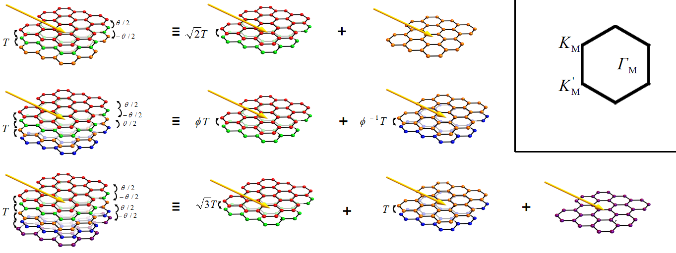
In this paper, we study the effect of circularly polarized light on ATMG. Interestingly, we find that, under the high-frequency limit, irradiated ATMG can be mapped to irradiated bilayer subsystems (plus a irradiated single layer), as illustrated in Fig. 1. This mapping is similar to those with an electric field or a magnetic field [28, 29, 30], but there is no decay factor rescaling the light field. In particular, despite the existence of a Dirac cone at the point, the light field induces gap opening and isolates the central Floquet band (see Fig. 2), and thus changes the topology of the flat band. The model is given in Sec. II and the mapping is presented in Sec. III. In Sec. IV, we calculate the Floquet band spectrum in trilayer graphene and show the existence of the Floquet topological flat band. The numerical results for layers are presented in Sec. V. Since the coupling ratio is layer dependent and sensitive to lattice relaxation in ATMG [64, 28], we check the existence of Floquet topological flat band at the first magic angle and its corresponding effective in different layers. The advantages of the Floquet method on ATMG are addressed in the Conclusion in Sec. VI.
II Model
Now we consider a general system of -layer ATMG irradiated by a beam of circularly polarized light. The relative twist between two neighboring layers has the same magnitude but alters in sign (). Here, the relative displacement is neglected since the zero shift configuration is energetically favorable [28]. The electromagnetic vector potential of the light is given by with the time, the frequency, and the field strength. The multiplication of and is the electric field amplitude, .
The low-energy physics of the system for one of the valleys can be modeled by
| (1) |
where , with rotated Pauli matrices and Fermi velocity , is the low-energy Dirac Hamiltonian of a valley of a single graphene sheet twisted by angle . The time-dependent electromagnetic potential is introduced into the Hamiltonian by way of minimal substitution. The interlayer tunneling matrix , with
| (2) |
where the unit vectors , encode the tunneling and between the - and -stacked regions of the TBG. is the wave vector of the Moiré pattern and is the Bravais lattice spacing of graphene.
In the Floquet theory, the periodically changed vector potential modifies the static Hamiltonian to . One focuses on quasienergies , and periodically changed Floquet modes , where is the period and is the crystal momentum, by solving the Floquet-Schrödinger equation . The quasienergies fall into a so-called Floquet zone with size similar to the concept of the Brillouin zone but in the time dimension. The relation between Floquet modes and the wave function governed by the time-dependent Schrödinger equation is .
The simulation parameters are chosen from the experimentally known electronic structure [65] as follows: Å, eV, and meV . Correspondingly, is a function of the twist angle . Throughout this paper, the laser parameters are chosen to be and , which are experimentally attainable. Under this circumstance, the relevant energy scales of the low-lying bands are much lower than the Floquet sidebands, and thus the admixture with the Floquet sideband can be neglected in our following discussions.
The interlayer tunneling around the magic angle is affected by atomic relaxation. Especially, this relaxation effect becomes stronger with the number of layers being increased [28, 66]. The relaxation of atoms in multilayer geometry will decrease the interlayer distance at stacking and increase the one at stacking. This reduces the tunneling and increases the tunneling , and thus changing their ratio . In trilayer graphene (), the first-principles calculation gives the value of the first magic angle and the effective . For , the distinction between tunneling at inner and outer interfaces changes the value of the magic angle. For , the value of the first magic angle is and the effective . For , the second magic angle is within reach. The value of the first and second magic angles are and , and the corresponding effective are and [28].
III The reduction of effective Hamiltonian in the high-frequency limit
In the high-frequency limit, light does not directly excite electrons and instead effectively modifies the electron band structures. Its influence can be represented by an effective static Hamiltonian , where is the time-evolution operator, with being the time-ordering operator. For , we consider the . Here, for are the Fourier components of the periodic Hamiltonian.
Now we have the effective Hamiltonian , where the static part with being set to zero and the modification part being
| (3) |
Here, and is an -dimensional identity matrices for an -layer system. is a Pauli matrix acting on the individual layer’s sublattice degree of freedom, and thus breaks time-reversal symmetry.
Following a similar procedure in static systems [29], we continue to decompose the effective Hamiltonian for layers irradiated ATMG using a unitary transformation. The transformation is a -dimensional transformation matrix, which is given in Refs. 29, 64. Using the unitary transformation on the static part and the modification part of separately, we have .
After the transformation, the static Hamiltonian generates a TBG subsystem . For different layers of ATMG, the remaining subsystems that arise from the static Hamiltonian can be graphene, non-TBG, or their combinations. For the modification part, since is independent of the sublattices, the transformation leaves unchanged. That is, . From the fact that the modification parts can be written as a direct sum of terms, , we have
| (4) |
For TBG, the corresponding term becomes . For single-layer graphene, the corresponding term becomes . From Eq. (4), the effect of a beam of circularly polarized light on the ATMG can be presented by multiple independent beams of circularly polarized light on each subsystem, as shown in Fig. 1.
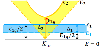
One of the remarkable consequences is that the modifies the low-energy electron band structure. To illustrate the effect of light, we consider a three-layer ATMG as shown in Fig. 2. We focus on the two lowest positive energy bands. For static bands (), while the lowest one () is a flat band in the TBG subsystem, the second one from the other subsystem () hosts a Dirac cone at the point. The effect of light on the two subsystems can be shown by the shifts of the two lowest Floquet energy levels (). Actually, as evident in Fig. 2, the gap openings in the low-energy subsystems at the point isolate the central Floquet band . The band gap between the positive and negative central Floquet bands is nonzero and is twice the distance between and zero energy , with being the gap opening of the lower energy level in TBG subsystem. For the band gap above the positive central Floquet band , we should discuss and cases separately. In the chiral limit (), the static bands and touch each other at zero energy, i.e., . The Floquet band gap . The shift of the Dirac cone under term is . can be calculated from the eigenenergies of as . Thus, the gap keeps closing at points for . In contrast, for , . is independent of and always equal to . In TBG system, is always smaller than the value at zero [52], which means . Therefore, for finite , is smaller than and leads to the opening of gap .
From the above analysis, we can see that the polarized light on the ATMG opens the gaps and at the point and isolate the flat band with . This can be generalized to ATMG with .
Actually, the phase difference between the and components of the circularly polarized light can be different, which is the elliptically polarized light case . In this case, the above analysis can also be true with the factor in Eq. (3) being , except for the linearly polarized case in which leads to the vanishing of the term.
IV The trilayer case ()
To check the isolation of the central Floquet band, we now examine the ATMG Floquet spectrum numerically.
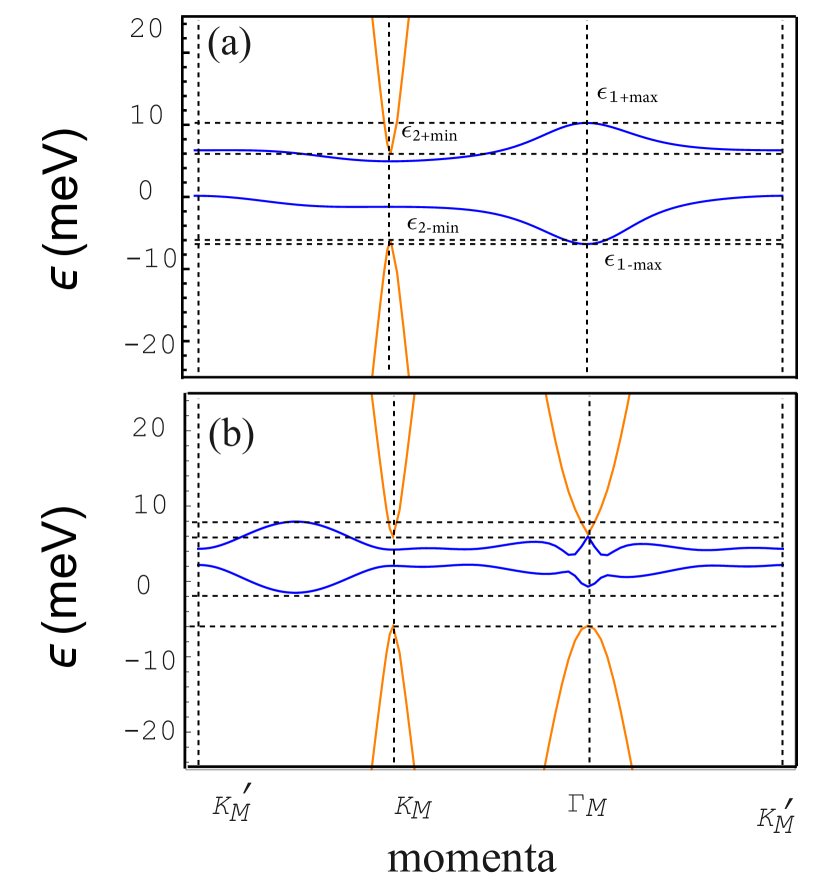
The Floquet spectrum can be calculated numerically by the Hamiltonian Eq. (1) via the Floquet-Schrödinger approach. The Floquet spectrum shown in Fig. 3(a) is at the first magic angle and the corresponding tunneling ratio chosen from the lattice relaxation result. The spectrum exhibits apparent electron-hole asymmetry due to the relaxation [10]. Similar to the TBG case, the hole side gets much wider than the electron side. The positive (negative) central Floquet energy bands corresponds to the lower band of the TBG subsystem. And the Floquet band next to the central one corresponds to the graphene subsystem and hosts a steep Dirac cone at point, which is absent in TBG system.
While the gap opening at the point for finite is proved in the last section, the indirect gap between the minimum value of and the maximal value of is not always opened. Figure 3(a) shows that the minimal of at point is lower than the maximal value of at point, giving a negative indirect gap. Thus, we should use the direct gap instead of the indirect one to characterize the band feature.
A numerical calculation of Chern numbers at [Fig. 3 (a)] gives a nontrivial topological number . This can be understood from the fact that time-reversal breaking induces valley and spin degeneracies in the irradiation ATMG system, similar to the TBG case [52]. In Fig. 3(b), for , however, a gap closing takes place at the points and gives a trivial Chern number. Thus, it is necessary to investigate the band features under different effective interlayer tunneling and twist angle .
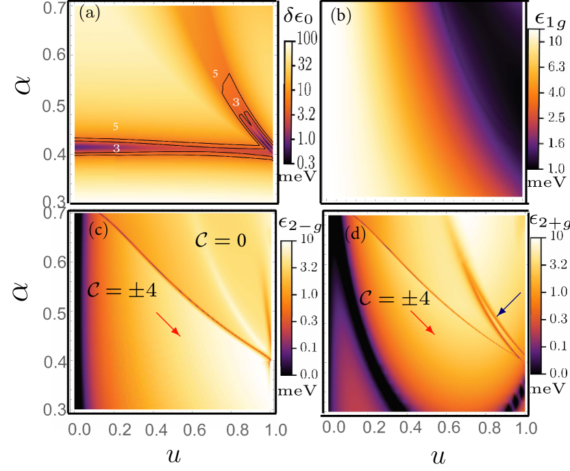
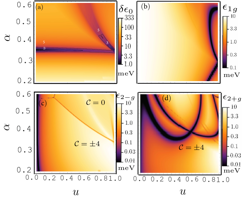
Now we show the phase diagrams for the bandwidth and band gaps of the central Floquet band. The bandwidth of the two central bands is shown in Fig. 4(a), sharing many similarities to the irradiated TBG. In particular, the irradiated ATMG has advantages over static cases. First, the flat bands exist over a wider range of twist angles. This is true in both regions: the one around the magic angle () in the whole range of and the one at and large . Second, the bandwidths of the lowest energy bands in the irradiated case are smaller than those in the static case. This is obvious near the chiral limit () and small twist angle (). The most important characteristic of ATMG is that the flat band regions are at larger twist angles than irradiated TBG. This can be understood from the fact that the magic angle of three-layer ATMG is , which is larger than the one of TBG.
Before searching the topological region of the flat band, we should find the band isolation regions by calculating the band gaps. The gap can be seen in Fig. 4(b). It becomes smaller with increasing but remains non-vanishing in the entire regions. This is consistent with the TBG case since the bands belong to the TBG subsystems.
The situation for the gap is more complicated. Due to the electron-hole asymmetry, the and gaps for the electron and hole parts are not the same. Figure 4(c) exhibits fewer dark regions which correspond to fewer gap closings. This can be understood from the fact that the hole part of the spectrum is wider than the electron part.
For the gap, we found two gap closings. The first gap closing at point is around the chiral limit , as discussed in Sec. III. As the interlayer tunneling ratio increases, another gap closing appears at the point for large , as given in Fig. 3(b). The region between the two gap closings is topological. Remarkably, the flat band at the first magic angle and its corresponding effective interlayer ratio from lattice relaxation calculation falls into this topological region (marked by a red star).
For the positive energy, the phase diagram of [Fig. 4(d)] exhibits two additional gap closings at the point for smaller twist angles closing to . They are very close to the gap closings in the TBG case (see Fig. 3(b) in Ref. [52]) with a amplification factor on the axis.
Therefore, although the gap closings at the point make the phase diagram for ATMG more complicated, they have no influence on the existence of the topological isolated flat bands at the first magic angle, whose twist angle is larger than the one of TBG.
V
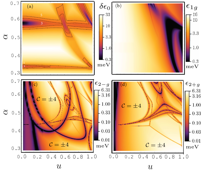
For an ATMG system with more layers, more subsystems appear after decomposition. We should look at their influences on the central Floquet bandwidth and bandgaps.
According to the discussion in Sec. III, we know that the laser field opens gaps in the TBG subsystem for ATMG with different layer numbers. Most importantly, for ATMG, except the interlayer tunneling, both the laser parameter and intralayer tunneling in the TBG subsystem do not depend on the layer number. We expect that the bandwidth and the band gap phase diagram in Figs. 5(a), 5(b), 6(a), 6(b) are similar to the bilayer and the trilayer cases.
Actually, the increment of subsystems changes the gap. The gap for and are shown in Figs. 5(c) and 6(c). As a result of particle-hole asymmetry, the gap is more complicated and is shown in Figs. 5(d) and 6(d). For , the ATMG decomposes into a TBG subsystem and a nonmagic TBG subsystem. The nonmagic TBG subsystem, which is away from the magic angles, hosts Dirac cones at and points. When these Dirac cones touch the lowest energy level , they close the band gap . This is similar to the effect of the Dirac cone of the graphene subsystem in the trilayer system. In Fig. 5(d), we can see that the gap closing changes the phase diagram. However, the gap at the first magic angle is opened, and thus the central band is topologically nontrivial.
For the case, there are a non-TBG subsystem and a graphene subsystem besides the TBG subsystem. The appearance of Dirac cones in either the nonmagic TBG or the graphene subsystem closes the gap. As a result, a more complicated phase diagram is found in Figs. 6(c) and 6(d). The bands at the two first magic angles are in the gapped and topological phases.
VI Discussion and Conclusion
In this paper, we have investigated irradiated ATMG at charge neutral. By mapping the multilayer system into a direct sum of bilayer systems (plus a single-layer system), we have shown that the laser field opens gaps between the central Floquet flat bands and between the ones next to them for . Numerical results of further show that the gap opening makes the Floquet flat bands topological in certain twist angle and tunneling ratio regions despite the complicated gap closing features at and points induced by the coexisting Dirac cones. These findings extend the Floquet study on TBG and other multilayer graphene systems, confirming the existence of the topological Floquet flat band in ATMG.
Floquet engineering ATMG is a promising platform to realize the Floquet fractional Chern insulators, which can be seen in two ways. First, compared to other multilayer systems studied in the literature, the flat band in ATMG is more stable. Distinguishing from trilayer graphene stacked on hexagonal boron nitride or twisted double bilayer graphene, does not exhibit magic angles or flat bands when realistic effects, e.g., trigonal warping terms, are included. Most notably, we study the ATMG by decomposing it into several subsystems and find that the coupling of the laser field to the system is intra-subsystem and does not decay with the increasing layer number, which is more controllable to open gaps than other techniques.
Acknowledgements.
This work is supported by the National Natural Science Foundation of China (Grant No. 12104099).References
- Cao et al. [2018a] Y. Cao, V. Fatemi, A. Demir, S. Fang, S. L. Tomarken, J. Y. Luo, J. D. Sanchez-Yamagishi, K. Watanabe, T. Taniguchi, E. Kaxiras, et al., Correlated insulator behaviour at half-filling in magic-angle graphene superlattices, Nature 556, 80 (2018a).
- Cao et al. [2018b] Y. Cao, V. Fatemi, S. Fang, K. Watanabe, T. Taniguchi, E. Kaxiras, and P. Jarillo-Herrero, Unconventional superconductivity in magic-angle graphene superlattices, Nature 556, 43 (2018b).
- Yankowitz et al. [2019] M. Yankowitz, S. Chen, H. Polshyn, Y. Zhang, K. Watanabe, T. Taniguchi, D. Graf, A. F. Young, and C. R. Dean, Tuning superconductivity in twisted bilayer graphene, Science 363, 1059 (2019).
- Bistritzer and MacDonald [2011] R. Bistritzer and A. H. MacDonald, Moiré bands in twisted double-layer graphene, Proceedings of the National Academy of Sciences 108, 12233 (2011).
- Dos Santos et al. [2007] J. L. Dos Santos, N. Peres, and A. C. Neto, Graphene bilayer with a twist: Electronic structure, Physical review letters 99, 256802 (2007).
- Sharpe et al. [2019] A. L. Sharpe, E. J. Fox, A. W. Barnard, J. Finney, K. Watanabe, T. Taniguchi, M. Kastner, and D. Goldhaber-Gordon, Emergent ferromagnetism near three-quarters filling in twisted bilayer graphene, Science 365, 605 (2019).
- Zhang et al. [2019a] Y.-H. Zhang, D. Mao, and T. Senthil, Twisted bilayer graphene aligned with hexagonal boron nitride: anomalous hall effect and a lattice model, Physical Review Research 1, 033126 (2019a).
- Bultinck et al. [2020] N. Bultinck, E. Khalaf, S. Liu, S. Chatterjee, A. Vishwanath, and M. P. Zaletel, Ground state and hidden symmetry of magic-angle graphene at even integer filling, Phys. Rev. X 10, 031034 (2020).
- Song et al. [2019] Z. Song, Z. Wang, W. Shi, G. Li, C. Fang, and B. A. Bernevig, All magic angles in twisted bilayer graphene are topological, Physical review letters 123, 036401 (2019).
- Song et al. [2021] Z.-D. Song, B. Lian, N. Regnault, and B. A. Bernevig, Twisted bilayer graphene. ii. stable symmetry anomaly, Phys. Rev. B 103, 205412 (2021).
- Lian et al. [2021] B. Lian, Z.-D. Song, N. Regnault, D. K. Efetov, A. Yazdani, and B. A. Bernevig, Twisted bilayer graphene. iv. exact insulator ground states and phase diagram, Phys. Rev. B 103, 205414 (2021).
- Shen et al. [2021] C. Shen, J. Ying, L. Liu, J. Liu, N. Li, S. Wang, J. Tang, Y. Zhao, Y. Chu, K. Watanabe, T. Taniguchi, R. Yang, D. Shi, F. Qu, L. Lu, W. Yang, and G. Zhang, Emergence of chern insulating states in non-magic angle twisted bilayer graphene, Chinese Physics Letters 38, 047301 (2021).
- Abouelkomsan et al. [2020] A. Abouelkomsan, Z. Liu, and E. J. Bergholtz, Particle-hole duality, emergent fermi liquids, and fractional chern insulators in moiré flatbands, Physical review letters 124, 106803 (2020).
- Repellin and Senthil [2020] C. Repellin and T. Senthil, Chern bands of twisted bilayer graphene: Fractional chern insulators and spin phase transition, Physical Review Research 2, 023238 (2020).
- Wilhelm et al. [2021] P. Wilhelm, T. C. Lang, and A. M. Läuchli, Interplay of fractional chern insulator and charge density wave phases in twisted bilayer graphene, Physical Review B 103, 125406 (2021).
- Xie et al. [2021] Y. Xie, A. T. Pierce, J. M. Park, D. E. Parker, E. Khalaf, P. Ledwith, Y. Cao, S. H. Lee, S. Chen, P. R. Forrester, et al., Fractional chern insulators in magic-angle twisted bilayer graphene, Nature 600, 439 (2021).
- Mora et al. [2019] C. Mora, N. Regnault, and B. A. Bernevig, Flatbands and perfect metal in trilayer moiré graphene, Physical review letters 123, 026402 (2019).
- Cea et al. [2019] T. Cea, N. R. Walet, and F. Guinea, Twists and the electronic structure of graphitic materials, Nano letters 19, 8683 (2019).
- Zhu et al. [2020] Z. Zhu, S. Carr, D. Massatt, M. Luskin, and E. Kaxiras, Twisted trilayer graphene: A precisely tunable platform for correlated electrons, Physical review letters 125, 116404 (2020).
- Mao et al. [2023] Y. Mao, D. Guerci, and C. Mora, Supermoiré low-energy effective theory of twisted trilayer graphene, Physical Review B 107, 125423 (2023).
- Lin et al. [2022] X. Lin, C. Li, K. Su, and J. Ni, Energetic stability and spatial inhomogeneity in the local electronic structure of relaxed twisted trilayer graphene, Physical Review B 106, 075423 (2022).
- Ma et al. [2023] Z. Ma, S. Li, M. Lu, D.-H. Xu, J.-H. Gao, and X. Xie, Doubled moiré flat bands in double-twisted few-layer graphite, Science China Physics, Mechanics & Astronomy 66, 227211 (2023).
- Hao et al. [2021] Z. Hao, A. Zimmerman, P. Ledwith, E. Khalaf, D. H. Najafabadi, K. Watanabe, T. Taniguchi, A. Vishwanath, and P. Kim, Electric field–tunable superconductivity in alternating-twist magic-angle trilayer graphene, Science 371, 1133 (2021).
- Lake and Senthil [2021] E. Lake and T. Senthil, Reentrant superconductivity through a quantum lifshitz transition in twisted trilayer graphene, Phys. Rev. B 104, 174505 (2021).
- Qin and MacDonald [2021] W. Qin and A. H. MacDonald, In-plane critical magnetic fields in magic-angle twisted trilayer graphene, Physical Review Letters 127, 097001 (2021).
- Park et al. [2022] J. M. Park, Y. Cao, L.-Q. Xia, S. Sun, K. Watanabe, T. Taniguchi, and P. Jarillo-Herrero, Robust superconductivity in magic-angle multilayer graphene family, Nature Materials 21, 877 (2022).
- Zhang et al. [2022] Y. Zhang, R. Polski, C. Lewandowski, A. Thomson, Y. Peng, Y. Choi, H. Kim, K. Watanabe, T. Taniguchi, J. Alicea, et al., Promotion of superconductivity in magic-angle graphene multilayers, Science 377, 1538 (2022).
- Ledwith et al. [2021] P. J. Ledwith, E. Khalaf, Z. Zhu, S. Carr, E. Kaxiras, and A. Vishwanath, Tb or not tb? contrasting properties of twisted bilayer graphene and the alternating twist -layer structures (), arXiv preprint arXiv:2111.11060 (2021).
- Khalaf et al. [2019] E. Khalaf, A. J. Kruchkov, G. Tarnopolsky, and A. Vishwanath, Magic angle hierarchy in twisted graphene multilayers, Physical Review B 100, 085109 (2019).
- Popov and Tarnopolsky [2023] F. K. Popov and G. Tarnopolsky, Magic angles in equal-twist trilayer graphene, arXiv preprint arXiv:2303.15505 (2023).
- Chen et al. [2019] G. Chen, A. L. Sharpe, P. Gallagher, I. T. Rosen, E. J. Fox, L. Jiang, B. Lyu, H. Li, K. Watanabe, T. Taniguchi, et al., Signatures of tunable superconductivity in a trilayer graphene moiré superlattice, Nature 572, 215 (2019).
- Chen et al. [2020] G. Chen, A. L. Sharpe, E. J. Fox, Y.-H. Zhang, S. Wang, L. Jiang, B. Lyu, H. Li, K. Watanabe, T. Taniguchi, et al., Tunable correlated chern insulator and ferromagnetism in a moiré superlattice, Nature 579, 56 (2020).
- Zhang et al. [2019b] Y.-H. Zhang, D. Mao, Y. Cao, P. Jarillo-Herrero, and T. Senthil, Nearly flat chern bands in moiré superlattices, Physical Review B 99, 075127 (2019b).
- Liu et al. [2022] Z. Liu, W. Shi, T. Yang, and Z. Zhang, Magic angles and flat chern bands in alternating-twist multilayer graphene system, Journal of Materials Science & Technology 111, 28 (2022).
- Xie et al. [2022] B. Xie, R. Peng, S. Zhang, and J. Liu, Alternating twisted multilayer graphene: generic partition rules, double flat bands, and orbital magnetoelectric effect, npj Computational Materials 8, 1 (2022).
- Liu et al. [2020] X. Liu, Z. Hao, E. Khalaf, J. Y. Lee, Y. Ronen, H. Yoo, D. Haei Najafabadi, K. Watanabe, T. Taniguchi, A. Vishwanath, et al., Tunable spin-polarized correlated states in twisted double bilayer graphene, Nature 583, 221 (2020).
- Lee et al. [2019] J. Y. Lee, E. Khalaf, S. Liu, X. Liu, Z. Hao, P. Kim, and A. Vishwanath, Theory of correlated insulating behaviour and spin-triplet superconductivity in twisted double bilayer graphene, Nature communications 10, 5333 (2019).
- Cao et al. [2020] Y. Cao, D. Rodan-Legrain, O. Rubies-Bigorda, J. M. Park, K. Watanabe, T. Taniguchi, and P. Jarillo-Herrero, Tunable correlated states and spin-polarized phases in twisted bilayer–bilayer graphene, Nature 583, 215 (2020).
- Shen et al. [2020] C. Shen, Y. Chu, Q. Wu, N. Li, S. Wang, Y. Zhao, J. Tang, J. Liu, J. Tian, K. Watanabe, et al., Correlated states in twisted double bilayer graphene, Nature Physics 16, 520 (2020).
- Oka and Aoki [2009] T. Oka and H. Aoki, Photovoltaic hall effect in graphene, Phys. Rev. B 79, 081406(R) (2009).
- Gu et al. [2011] Z. Gu, H. A. Fertig, D. P. Arovas, and A. Auerbach, Floquet spectrum and transport through an irradiated graphene ribbon, Phys. Rev. Lett. 107, 216601 (2011).
- Kitagawa et al. [2011] T. Kitagawa, T. Oka, A. Brataas, L. Fu, and E. Demler, Transport properties of nonequilibrium systems under the application of light: Photoinduced quantum hall insulators without landau levels, Phys. Rev. B 84, 235108 (2011).
- Dóra et al. [2012] B. Dóra, J. Cayssol, F. Simon, and R. Moessner, Optically engineering the topological properties of a spin hall insulator, Phys. Rev. Lett. 108, 056602 (2012).
- Iadecola et al. [2013] T. Iadecola, D. Campbell, C. Chamon, C.-Y. Hou, R. Jackiw, S.-Y. Pi, and S. V. Kusminskiy, Materials design from nonequilibrium steady states: Driven graphene as a tunable semiconductor with topological properties, Phys. Rev. Lett. 110, 176603 (2013).
- Syzranov et al. [2013] S. V. Syzranov, Y. I. Rodionov, K. I. Kugel, and F. Nori, Strongly anisotropic dirac quasiparticles in irradiated graphene, Phys. Rev. B 88, 241112(R) (2013).
- Ezawa [2013] M. Ezawa, Photoinduced topological phase transition and a single dirac-cone state in silicene, Phys. Rev. Lett. 110, 026603 (2013).
- Kundu et al. [2014] A. Kundu, H. Fertig, and B. Seradjeh, Effective theory of floquet topological transitions, Physical review letters 113, 236803 (2014).
- Grushin et al. [2014] A. G. Grushin, Á. Gómez-León, and T. Neupert, Floquet fractional chern insulators, Physical review letters 112, 156801 (2014).
- Kundu et al. [2016] A. Kundu, H. A. Fertig, and B. Seradjeh, Floquet-engineered valleytronics in dirac systems, Phys. Rev. Lett. 116, 016802 (2016).
- Rudner and Lindner [2020] M. S. Rudner and N. H. Lindner, Band structure engineering and non-equilibrium dynamics in floquet topological insulators, Nature reviews physics 2, 229 (2020).
- Sentef et al. [2015] M. Sentef, M. Claassen, A. Kemper, B. Moritz, T. Oka, J. Freericks, and T. Devereaux, Theory of floquet band formation and local pseudospin textures in pump-probe photoemission of graphene, Nature communications 6, 7047 (2015).
- Li et al. [2020] Y. Li, H. Fertig, and B. Seradjeh, Floquet-engineered topological flat bands in irradiated twisted bilayer graphene, Physical Review Research 2, 043275 (2020).
- Yang et al. [2023] C. Yang, I. Esin, C. Lewandowski, and G. Refael, Optical control of slow topological electrons in moiré systems, Phys. Rev. Lett. 131, 026901 (2023).
- Hu et al. [2023] P.-S. Hu, Y.-H. Zhou, and Z. Liu, Floquet fractional chern insulators and competing phases in twisted bilayer graphene, SciPost Physics 15, 148 (2023).
- Vogl et al. [2020a] M. Vogl, M. Rodriguez-Vega, and G. A. Fiete, Effective floquet hamiltonians for periodically driven twisted bilayer graphene, Physical Review B 101, 235411 (2020a).
- Vogl et al. [2020b] M. Vogl, M. Rodriguez-Vega, and G. A. Fiete, Floquet engineering of interlayer couplings: Tuning the magic angle of twisted bilayer graphene at the exit of a waveguide, Physical Review B 101, 241408(R) (2020b).
- Katz et al. [2020] O. Katz, G. Refael, and N. H. Lindner, Optically induced flat bands in twisted bilayer graphene, Physical Review B 102, 155123 (2020).
- Topp et al. [2019] G. E. Topp, G. Jotzu, J. W. McIver, L. Xian, A. Rubio, and M. A. Sentef, Topological floquet engineering of twisted bilayer graphene, Phys. Rev. Res. 1, 023031 (2019).
- Topp et al. [2021] G. E. Topp, C. J. Eckhardt, D. M. Kennes, M. A. Sentef, and P. Törmä, Light-matter coupling and quantum geometry in moiré materials, Phys. Rev. B 104, 064306 (2021).
- Rodriguez-Vega et al. [2021] M. Rodriguez-Vega, M. Vogl, and G. A. Fiete, Low-frequency and moiré–floquet engineering: A review, Annals of Physics 435, 168434 (2021).
- Rodriguez-Vega et al. [2020] M. Rodriguez-Vega, M. Vogl, and G. A. Fiete, Floquet engineering of twisted double bilayer graphene, Physical Review Research 2, 033494 (2020).
- Assi et al. [2021] I. Assi, J. LeBlanc, M. Rodriguez-Vega, H. Bahlouli, and M. Vogl, Floquet engineering and nonequilibrium topological maps in twisted trilayer graphene, Physical Review B 104, 195429 (2021).
- Lu et al. [2021] M. Lu, J. Zeng, H. Liu, J.-H. Gao, and X. Xie, Valley-selective floquet chern flat bands in twisted multilayer graphene, Physical Review B 103, 195146 (2021).
- Ledwith et al. [2020] P. J. Ledwith, G. Tarnopolsky, E. Khalaf, and A. Vishwanath, Fractional chern insulator states in twisted bilayer graphene: An analytical approach, Phys. Rev. Res. 2, 023237 (2020).
- Kuzmenko et al. [2009] A. Kuzmenko, I. Crassee, D. Van Der Marel, P. Blake, and K. Novoselov, Determination of the gate-tunable band gap and tight-binding parameters in bilayer graphene using infrared spectroscopy, Physical Review B 80, 165406 (2009).
- Leconte et al. [2022] N. Leconte, Y. Park, J. An, A. Samudrala, and J. Jung, Electronic structure of lattice relaxed alternating twist tng-multilayer graphene: from few layers to bulk at-graphite, 2D Materials 9, 044002 (2022).