ACHIEVING ULTRA-RELIABLE LOW-LATENCY COMMUNICATION (URLLC) IN NEXT-GENERATION CELLULAR NETWORKS WITH PROGRAMMABLE DATA PLANES
by
Kerim Gökarslan
B.S., Computer Engineering, Boğaziçi University, 2017
B.S., Mathematics, Boğaziçi University, 2017
M.S., Computer Science, Yale University, 2020
MBA, Quantic School of Business and Technology, 2021
Submitted to the Institute for Graduate Studies in
Science and Engineering in partial fulfillment of
the requirements for the degree of
Master of Science
Graduate Program in Computer Engineering
Boğaziçi University
2022
Abstract
Recent advancements in wireless technologies towards the next-generation cellular networks have brought a new era that made it possible to apply cellular technology on traditionally-wired networks with tighter requirements, such as industrial networks. The next-generation cellular technologies (e.g., 5G and Beyond) introduce the concept of ultra-reliable low-latency communications (URLLC). This thesis presents a Software-Defined Networking (SDN) architecture with programmable data planes for the next-generation cellular networks to achieve URLLC. Our design deploys programmable switches between the cellular core and Radio Access Networks (RAN) to monitor and modify data traffic at the line speed. We introduce the concept of intra-cellular optimization, a relaxation in cellular networks to allow pre-authorized in-network devices to communicate without being required to signal the core network. We also present a control structure, Unified Control Plane (UCP), containing a novel Ethernet Layer control protocol and an adapted version of link-state routing information distribution among the programmable switches. Our implementation uses P4 with an 5G implementation (Open5Gs) and a UE/RAN simulator. We implement a Python simulator to evaluate the performance of our system on multi-switch topologies by simulating the switch behavior. Our evaluation indicates latency reduction up to 2x with intra-cellular optimization compared to the conventional architecture. We show that our design has a ten-millisecond level of control latency, and achieves fine-grained network security and monitoring.
ACHIEVING ULTRA-RELIABLE LOW-LATENCY COMMUNICATION (URLLC) IN NEXT-GENERATION CELLULAR NETWORKS WITH PROGRAMMABLE DATA PLANES
APPROVED BY:
| Prof. Tuna Tuğcu | |
| (Thesis Supervisor) | |
| Prof. Berk Canberk | |
| Prof. Ali Emre Pusane | |
DATE OF APPROVAL: 03.06.2022
``\accdasiaο δ\accvariaε \accpsiliανεξ\acctonosεταςτος β\acctonosιος ο\accpsiliυ βιωτ\accvariaος \accpsiliανϑρ\acctonosωπ᾽
Σωϰρ\acctonosατης
“Dünyada her şey için, maddiyat için, maneviyat için, hayat için, başarı için en hakikî yol gösterici ilimdir, fendir. İlim ve fennin dışında yol gösterici aramak gaflettir, cahilliktir, doğru yoldan sapmaktır.”
M. Kemal Atatürk
“The unexamined life is not worth living for a human being.”
Socrates
“Science is the most real guide for civilisation, for life, for success in the world. To search for a guide other than science is absurdity, ignorance and heresy.”
M. Kemal Atatürk
ACKNOWLEDGEMENTS
This thesis and most of my academic achievements would not be possible if I didn’t have the chance to meet with Prof. Tuna Tugcu back in 2012 when I was a senior high school student to work on a then cutting-edge Bluetooth/GPS cooperation project that we developed for the TUBITAK’s high school project contest. He led me to the way that I ended up at Yale, and thanks to him, I truly understood what I like and what I don’t about science and engineering. And today, after two bachelor’s degrees and being a candidate for my third master’s degree, I look back on my ten years, and I feel highly empowered to achieve tomorrow.
Further, I would like to thank Prof. Ali Emre Pusane and Prof. Arda Yurdakul for their letters of recommendation on my way to Yale. I thank all of the professors I work with, even though numerous of them only taught me what professorship is not about and how professors should not act.
And my personal life: I want to thank all of my friends, from high school to Bogazici, then at Yale, and finally at the companies I worked for. Most importantly, our extraordinary, mad, and yet extremely successful group, İSTİKRAR. Of course, I would not be the person today if it weren’t for my parents and brother. They have always had my back and supported me no matter what, and I am glad to have their sincere support.
ÖZET
PROGRAMLANABİLİR VERİ DÜZLEMLERİ İLE GELECEK NESİL HÜCRESEL AĞLARDA AŞIRI GÜVENİLİR DÜŞÜK GECİKMELİ İLETİŞİM’İN SAĞLANMASI (URLLC)
Yeni nesil kablosuz hücresel ağlardaki son gelişmeler, hücresel teknolojinin endüstriyel ağlar gibi daha ağır gereksinimleri olan ve geleneksel olarak kablolu ağlar kullanan sistemlerde uygulanmasını mümkün kılan yeni bir dönem getirdi. Yeni nesil hücresel teknolojiler (ör. 5G ve Ötesi), aşırı güvenilir düşük gecikmeli iletişim (URLLC) konseptini ortaya çıkardı. Bu tezde, URLLC’yi elde etmek için yeni nesil hücresel ağlarda programlanabilir veri düzlemleriyle Yazılım Tanımlı Ağ (SDN) mimarisini öneriyoruz. Tasarımımız, veri trafiğini hat hızında kontrol etmek için hücresel çekirdek ile Radyo Erişim Ağı (RAN) arasında programlanabilir ağ anahtarları kullanıyor. Önceden yetkilendirilmiş ağ içi cihazların çekirdek ağa sinyal göndermesi gerekmeden iletişim kurmasını sağlamak için bir gevşetme olan hücreler arası eniyileme (eng. intra-cellular optimization) kavramını tanıtıyoruz. Ayrıca, programlanabilir anahtarlar arasında bilgi dağıtımı için tasarladığımız Birleştirilmiş Kontrol Düzlemi (eng. Unified Control Plane (UCP)) protokolünü sunuyoruz. Mimarimizi Open5Gs uygulaması, bir UE/RAN simülatörü ve P4 programlama dili kullanarak uygularken sistemimizin çoklu anahtar topolojilerindeki performansını geliştirdiğimiz Python simülatörü ile değerlendiriyoruz. Kapsamlı değerlendirmemiz, geleneksel mimariye kıyasla hücreler arası eniyileme ile gecikme süresinin iki kata kadar azaldığını gösteriyor.
TABLE OF CONTENTS
\@afterheading\@starttoc
toc
LIST OF FIGURES
\@starttoc
lof
LIST OF TABLES
\@starttoc
lot
LIST OF SYMBOLS
| gNB with identifier | |
| A link between nodes and | |
| Network | |
| Node with identifier | |
| A path between nodes and | |
| The set of non-negative rational numbers | |
| Switch with identifier | |
| TEID with identifier | |
| UPF | |
| UE with identifier |
LIST OF ACRONYMS/ABBREVIATIONS
| 1G | First Generation Cellular Networks |
| 2G | Second Generation Cellular Networks |
| 3G | Third Generation Cellular Networks |
| 3GPP | 3rd Generation Partnership Project |
| 4G | Fourth Generation Cellular Networks |
| 5G | Fifth Generation Cellular Networks |
| 6G | Sixth Generation Cellular Networks |
| AF | Application Function |
| AI | Artificial Intelligence |
| AMF | Access and Mobility Management |
| AN | Access Network |
| AUSF | Authentication Server Function |
| BMV2 | Behavioral Model version 2 |
| CAPEX | Capital Expenditures |
| CDR | Charging Data Record |
| CHF | Charging Function |
| CMI | Control Message Identifier |
| CN | Core Network |
| CPU | Central Process Unit |
| CUPS | Control and User Planee Seperation |
| DN | Data Network |
| ETSI | European Telecommunications Standard Institute |
| FSM | Finite State Machine |
| GHz | Gigahertz |
| GPRS | General Packet Radio Service |
| GTP | GRPS Tunneling Protocol |
| Gbps | Gigabits per second |
| HTTP | Hypertext Transport Protocol |
| ICMP | Internet Control Message Protocol |
| ID | Identity Document |
| IIoT | Industrial Internet of Things |
| IP | Internet Protocol |
| IPv4 | Internet Protocol version 4 |
| IPv6 | Internet Protocol version 6 |
| L2 | Layer 2 (Data Link Layer) |
| L3 | Layer 3 (Network Layer) |
| L4 | Layer 4 (Transport Layer) |
| LPM | Longest Prefix Match |
| LSR | Link State Routing |
| LTE | Long Term Evolution |
| M2M | Machine-to-Machine |
| MAC | Medium Access Control |
| MME | Mobility Management Entity |
| MTU | Maximum Transfer Unit |
| Mbps | Megatbits per second |
| NEF | Network Exposure Function |
| NF | Network Function |
| NG | Next Generation |
| NGAP | NG Application Protocol |
| NR | New Radio |
| NRF | Network Repository Function |
| NSSF | Network Slice Selection Function |
| NWDAF | Network Data Analytics Function |
| OPEX | Operating Expenses |
| OS | Operating System |
| OSPF | Open Shortest Path First |
| PCF | Policy Control Function |
| PCRF | Policy and Charging Rules Function |
| PDU | Protocol Data Unit |
| QoS | Quality of Service |
| RAM | Random Access Memory |
| RAN | Radio Access Network |
| RTT | Round-trip Time |
| SCP | Serrvice Communication Proxy |
| SCTP | Stream Control Transmission Protocol |
| SDN | Sfotware-Defined Networking |
| SMF | Session Management Function |
| SW | Switch |
| TCAM | Ternary Content-Addressable Memory |
| TCP | Transmission Control Protocol |
| TEID | Tunnel Endpoint Identifier |
| UCP | Unified Control Plane |
| UDM | Unified Data Management |
| UDP | User Datagram Protocol |
| UDR | Unified Data Repository |
| UE | User Equipment |
| UPF | User Plane Function |
| URLLC | Ultra-Reliable and Low-Latency Communication |
| VM | Virtual Machine |
| VR | Virtual Reality |
| WiMAX | Nobile Worldwide Interoperability for Microwave Access |
| dst | Destination |
| eMBB | Enhanced Mobile Broadband |
| gNB | Next Generation NodeB |
| mMTC | Massive Machine Type Communications |
| ms | Milliseconds |
| s | Seconds |
| src | Source |
| vCPU | Virtual Central Process Unit |
Chapter 1 INTRODUCTION
Wireless cellular systems have been rapidly evolving since the first generation (1G) based on analog voice communication was introduced in the late 1970s. The first digitalized cellular technology, the second-generation (2G), was introduced a decade later. The following extensions of 2G (e.g., GPRS) initially enabled the cellular networks to reach data rates around a couple of tens of Kbps in measurements [1], and later with introduction of EDGE such networks can reach upto 384 Kbps data rates. In the late 2000s, the third-generation (3G) cellular technology with transmission rates reaching Mbps was introduced. The 3G technology supports direct connection to Transmission Control Protocol/Internet Protocol (TCP/IP) based services, including the Internet [2]. As this was the turning point for cellular networks to transfer data rather than voice or video, the pressure to have better latency and data rate values increased. Consequently, the 3rd Generation Partnership Project (3GPP) has presented the standardization of the fourth-generation (4G) cellular systems, including the Long Term Evolution (LTE) along with Mobile Worldwide Interoperability for Microwave Access (WiMAX), which can offer data rates up to 50 Mbps [3]. Today, we see 5G deployments worldwide aiming to reach Gbps data rates with milliseconds-level latency values.
As recent developments in cellular technologies are the first steps for numerous latency-sensitive applications to switch to wireless networks, the future cellular technology generations (i.e., 5G and Beyond) have much room to improve latency while ensuring reliability. We, in fact, consider this trend within 5G to bring newer radio and core network design that aims at several use cases, including ultra-reliable low-latency communications (URLLC) aiming at mission-critical services such as industrial networks. With the introduction of such systems to cellular networks, we have started to see the trend of replacing wired networks with a cellular equivalent that targets to achieve similar requirements. Switching to wireless systems is indeed more profitable for network providers as wireless technologies can reduce both operating expenses (OPEX) (e.g., reduced maintenance costs) and capital expenditures (CAPEX) (e.g., planning and infrastructure costs) in many wired-network systems. Nevertheless, today’s cellular network technology is far from the expectation of 99.9999% reliability with 1 ms latency [4].
Initially introduced as a part of 5G New Radio (NR) by the 3GPP in the first complete set of 5G standards (Release 15) [5], URLLC aims to achieve 1 ms latency and target latency-sensitive applications, including industrial networks, smart grids, tactile internet [6], and autonomous driving. URLLC thus promises to be one of the critical features of not only the 5G but also the next generations of cellular networks. Unfortunately, achieving URLLC is not straightforward because of both the physical layer requirements and cellular networks’ current design. Apart from physical layer drawbacks, the current cellular network designs have numerous latency-unaware way of working that causes additional delays. This thesis focuses on low-latency applications at the packet processing level. It introduces a programmable data plane pipeline for URLLC in cellular networks to achieve lower latency. It targets 5G and Beyond cellular networks by introducing the concept of pre-authorization where some of the cellular network functions (e.g., Access and Mobility Management Function (AMF), Session Management Function (SMF)) are offloaded. We do so by leveraging the recent advancements in Software-Defined Networking (SDN), specifically using programmable data planes. In recent years, programmable data planes proved their value mainly in a data center or service-provider networks. In this thesis, we take a new approach to offload latency in cellular networks with higher intra-cellular communication (e.g., industrial cellular networks) using programmable data planes.
The principal idea of SDN is the decoupling of data and control paths into different devices to achieve more flexible and robust networks. In many SDN systems, the control plane runs as a centralized system that manages the network equipment responsible for the data plane in real-time. Further, these data plane devices have limited processing capabilities, such as processing pre-defined types of packets. In recent years, researchers have introduced the concept of programmable data planes, where the data planes devices can be programmed so that they can have customized behavior with the ability to process packets at the line rate. This consequently allows network administrators to define application-aware network behavior such as achieving latency-guarantees [7]. In this thesis, we use the P4 language [8] to implement our cellular-specific data plane (i.e., our data plane can parse and process cellular protocols such as GPRS Tunneling Protocol (GTP)) to achieve the aforementioned cellular network design and demonstrate it on a software switch.
1.1 Contributions of This Thesis
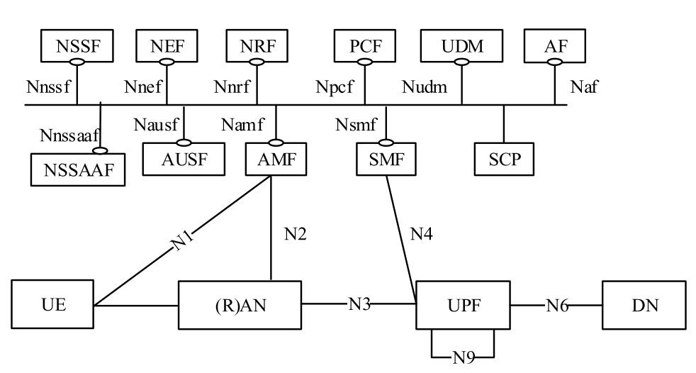
This thesis aims to achieve URLLC on 5G and Beyond cellular networks. While our high-level design can be applied to the newer generations of cellular networks such as 5G, we use the 5G - Release 16 version in our implementation; therefore, we discuss our implementation within the 5G specifications. As shown in Figure 1.1, 5G architecture consists of three main components: (a) User Equipment (UE); (b) Radio Access Network (RAN), and 5G core functions; and (c) User Plane Function (UPF) and Data Network (DN). The UE connects to the cellular network via RAN and communicates with other devices/outside world via UPF. RAN connects (via N2) to AMF, and UPF connects (via N4) to SMF on the cellular control path that is responsible for signaling including a UE initialization or handover. The traffic from and to the UE uses GTP over IP while it is carried between UE, RAN, and UPF. As we mainly focus on the cellular data path, this thesis does not discuss the other 5G core functions in detail.
The contributions of this thesis, therefore, are:
-
•
Introduction of the concept of intra-cellular optimization with cellular preauthorization to significantly reduce the latency between two cellular devices in the same cellular network,
-
•
Achieving data plane-assisted network security without requiring any modifications on the cellular network hardware or software,
-
•
Introducing fine-grained network monitoring for cellular networks via programmable data planes,
-
•
Introduction of a novel L2-layer protocol, Unified Control Plane (UCP), to control the programmable data plane that connects cellular network components in real-time,
-
•
Introduction of a mathematical model to study intra-cellular latency behavior in cellular networks,
-
•
One of the first research work that uses programmable data planes to parse both GTP and NGAP protocols.
Our evaluations and the analysis of the mathematical model of latency we develop indicate that our design can reduce data latency by a factor of two compared to traditional cellular network setups in 5G and Beyond. This optimization is practical, especially for non-traditional cellular systems such as industrial networks, where most devices (e.g., sensors) communicate within the network. One of the concerns for URLLC is the possibility of reduced network security and traceability; we show that our design can achieve detailed network monitoring and security using the capabilities of programmable data planes.
The rest of this thesis is organized as follows. Chapter 2 discusses the overview of the related work on cellular networks, SDN, and URLLC. Chapter 3 presents our novel architecture, including the UCP and the programmable data path. Chapter 4, then, discusses the details of our implementation. Chapter 5 gives the evaluation results. Chapter 6, finally, concludes the thesis with the future research directions.
Chapter 2 RELATED WORK
2.1 Cellular Networks: 5G and Beyond
Researchers categorize 5G and Beyond cellular networks under three categories: massive machine type communication (mMTC) addresses the applications with high data rates, enhanced mobile broadband (eMBB) concentrates on machine-to-machine (M2M) communication, and URLLC addresses low latency and highly available services including industry-grade cellular networks and tactile internet [10, 6].
As many countries have already started to deploy 5G networks, researchers have been working on the next-generation cellular networks, namely 5G and Beyond as well as the sixth generation (6G). A survey on 6G networks indicates that such next-generation networks are needed to achieve more cost-efficient and better quality of the use cases introduced in 5G, such as IoT, virtual reality (VR), and autonomous driving [11]. A recent survey [12] on RAN architectures in next-generation networks indicates SDN as a key to realizing high efficiency and high flexibility, and consequently, we focus on achieving URLLC with SDN in our work.
2.2 URLLC
As introduced with the 5G NR in the 3GPP standards URLLC targets non-traditional cellular networks aiming latency values on the order of milliseconds such as tactile internet, autonomous driving, and industrial networks. Numerous studies focus on the scheduling aspect of cellular networks to achieve URLLC. The authors of [13] study a joint scheduling schema for URLLC and eMBB aiming broadband utility while having URLLC requirements. Claiming to be the first formalization of the joint URLLC and eMBB scheduling, they propose a scheduling framework with linear, convex, and threshold models with theoretical guarantees on the algorithms.
Li et al. take a different approach on the same problem and use deep reinforcement learning to schedule URLLC and eMBB [14]. They use the deep deterministic policy gradient method to learn the tradeoff policy regarding reliability and service satisfaction.
[15] discusses URLLC techniques, including the AI-enabled edge caching frameworks focused on caching. Further, it discusses one of the most popular URLLC techniques, grant-free access, that decreases the control overhead via dynamic allocation of the resources. The authors of [15] also present a comprehensive study of URLLC while lacking SDN applications to achieve URLLC. Researchers in [16] examines the URLLC on 5G Releases 15, 16, and 17. The authors of [17] discuss diversity reception, automatic repeat query, and cognitive radio algorithm for 5G URLLC at a 28GHz link to overcome link degradation and interference to achieve lower latencies.
There are also a few studies discussing real-life use cases of URLLC technology. One such study in [18] discusses the case of an Indonesian Operator. They use the measurements of the existing network to propose the path to achieve the URLLC target of 1 ms with a design of data center locations. Another study discusses a scheme for factory automation targetting the resource allocation problem that enables autonomous driving within the factory [19].
2.3 SDN and Programmable Data Planes
SDN brings the concept of data plane and control plane separation, where the former contains the user data traffic and the latter contains the network control signals. Researchers have extensively applied SDN techniques to wireless networks in the last decade. SDN brings the concept of data plane and control plane separation, where the first one contains the user data traffic and the second one contains the network control signals. This separation, therefore, allows deployment of control plane to be centralized and the use of distributed data plane over the network.
SDN increases both interoperability and manageability of devices, as it allows generic data plane switches (e.g., OpenFlow [20]). When introducing a new protocol, such devices do not need a new hardware design, as they can be defined via software. This consequently decreases the development time and cost significantly.
One of the classical SDN design limitations is the limit of the data plane behavior. Many existing solutions focus on the operation of the 5-tuple of TCP/IP, thus lacking packet processing capabilities at the application layer. Programmable data planes have materialized to define user-specific data plane behavior at the line rate. Programmers can define customizable data paths with specific programmable data plane languages. One of such languages, P4 [8], has been extensively used in academia and industry in the last decade [21, 7]. This thesis uses P4 language to implement a software switch’s cellular network-specific data plane.
2.4 SDN in Cellular Networks
Researchers have extensively applied the SDN techniques to wireless networks in the last decade [22, 23, 24]. In [25], researchers indicate that SDN plays a crucial role in achieving a flexible and virtualized 5G network, although the many existing solutions are not SDN-ready, i.e., most SDN applications in the cellular networks are work-in-progress. The authors of [26] and [27] study network slicing on a 5G core network via decoupling UPF and SMF. [27] considers the dynamic traffic and structures the UPF programmable module integrated with SDN to give traffic flow rules to achieve network slicing in URLLC. It also introduces a different programmable switch to control the network flow and assure network security instead of replacing network functions with other programmable switches such as UPF or SMF. The authors of [26] do not consider any performance criteria such as latency, while [27] aims to decrease the latency with security considerations on private industrial 5G networks.
Many studies[28, 29] focuses to the user behavior and UPF with SDN on mobile environments. Researchers predict the user behavior via an SDN containing a foreseeing functionality of the UPF placement to reduce the user plane configuration delay. They further propose pre-configured UPF as a handover mechanism [28] uses the intermediate UPFs to anticipate the user behavior on SMF with a learning-based approach.
Chapter 3 ARCHITECTURE
In this chapter, we introduce the cellular network architecture with programmable switches. The first section describes the state-of-the-art 5G architecture and related network functions that we take as a basis for our implementation. Considering a minimal-to-none change in the cellular network architecture and implementation, we introduce our system running as a single P4-program on the P4 switches interconnecting the gNBs and core NFs as shown in Figure 1.1 in Section 3.2. The key idea for our design is to achieve URLLC while being seamless to users of the cellular network, i.e., users do not change their cellular network hardware or software. After a high-level introduction of our architecture in Section 3.2, we investigate our design in detail with three parts: (a) the unified control plane (UCP) that controls the P4 switches real-time using the high-level configuration from the network administration (Section 3.2.1). (b) the cellular control plane, where the P4 switch processes the control messages between gNB and AMF using NGAP (Section 3.3), (c) the cellular data plane, where the P4 switch processes the data packets between gNBs and UPF encapsulated using GTP (Section 3.4). We finally introduce our mathematical model for intra-cecullar latency estimation in cellular networks, which we use in our evaluation results in Section 3.5.
3.1 Cellular Network Architecture and Functions
In this section, we discuss the details of the 5G cellular network architecture since we take 5G architecture as the basis in our implementation. However, our architecture design is independent of the 5G network and can be adapted into newer cellular network generations. The Mobility Management Entity (MME) in 4G architecture, which is responsible for session and mobility management as well as the UE authentication, is split into three functions in 5G, AMF, SMF, and Authentication Server Function (AUSF) [30]. As our programmable data plane processes the signaling between gNBs and these control functions, we investigate the characteristics of the AMF, SMF, and AUSF, and partially implementing their functionality in the data path as described in Section 3.3. We further discuss the potential extensions in Chapter 6. The final subsection studies the cellular network’s data plane function, i.e., the UPF. Our programmable data path does not implement UPF itself; it introduces intra-cellular network optimization. The communication between two users in the same 5G network is processed at the switch interconnecting respective gNBs rather than the UPF to reduce latency.
3.1.1 Cellular Control Plane
As our programmable data plane design offloads some of the UE and cellular CN signaling, we describe related 5G NFs (i.e., AMF and SMF) and the NG Application Protocol (NGAP), which is the protocol for control signaling between 5G RAN and CN, in this section. We, furthermore, discuss other potential behaviors and NFs that can be offloaded by programmable design in Chapter 6.
3.1.1.1 NGAP
Specified by 3GPP, the NGAP defines the control signaling between RAN elements (i.e., UE and gNB) and cellular core via AMF [31]. NGAP consists of a wide variety of procedures, from PDU session establishment [32] and handover control to cell resource coordination. In this thesis, we focus on NGAP signaling for individual UE and process UE initialization packets. As our work mainly focuses on the cellular data plane, the NGAP processing only registers the IDs of UE with its respective gNB.
3.1.1.2 AMF
AMF is mainly responsible for handling mobility and connection management of the UE while it is the single point of contact with 5G-RAN, and consequently, the UE. AMF forwards the information related to UE to session management SMF using the N11 link.
3.1.1.3 SMF
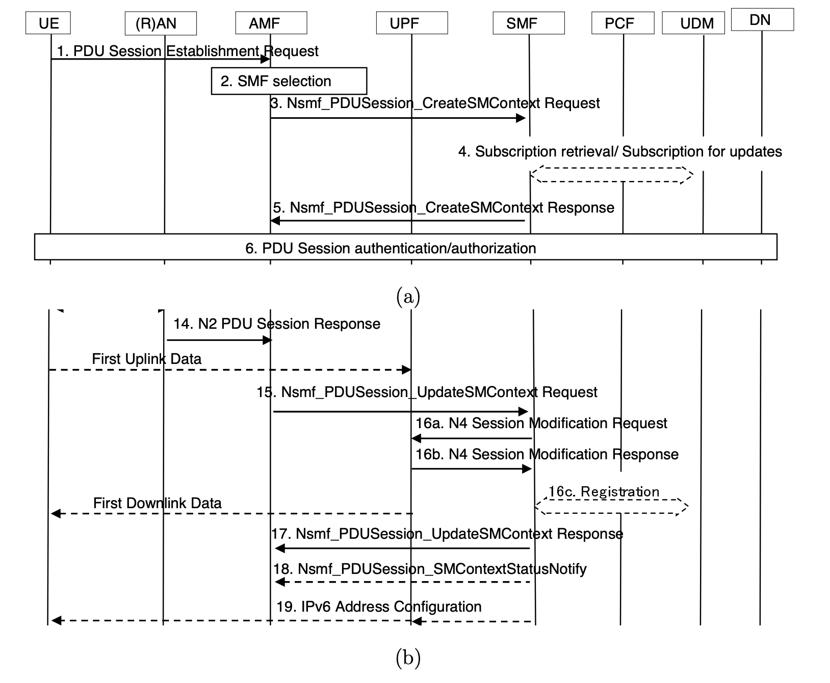
The SMF’s principal responsibility is to manage PDU sessions with the UPF via the N4 interface introduced with 5G. The UE connects to the cellular DN via UPF once the PDU session is established. A simplified UE initialization signalling for PDU session establishment is shown in Figure 3.2.
3.1.2 Cellular Data Plane
The UE data packets are encapsulated with GTP and transmitted between gNBs and UPF using N3, N6, and N9 interfaces as shown in Figure 1.1.
3.1.2.1 GTP
Unlike the aforementioned protocols and network functions, GTP has been used since the introduction of GPRS[35]. GTP is a protocol run on top of the TCP/IP or UDP/IP, and used to carry the UE data between RAN and core networks. GTP has two major versions, where older cellular generations deploy GTPv1 and newer generations, including 5G, use GTPv2. In addition to encapsulating user data, GTP is also used to check connectivity via echo messages.
| First Bit | Length (bit) | Field Description |
| 0 | 3 | Version |
| 3 | 1 | Piggybacking Flag |
| 4 | 1 | TEID Flag () |
| 5 | 3 | Spare |
| 8 | 8 | Message Type |
| 16 | 16 | Message Length |
| 32 | 32 | TEID when |
| 24 | Sequence Number |
As shown in Table 3.1, the GTP header contains the information about the user data that is encapsulates, and also includes the Tunnel Endpoint Identifier (TEID) that describes the tunnel between UE and gNB. Except for the echo messages, all GTP packets belong to a UE, and therefore GTP header carries the associated TEID. The sequence number indicates the order of the packet within the respective tunnel.
3.1.2.2 UPF
The 5G architecture brings the concept of control and user plane separation (CUPS) [37] to decouple the control functions from the data plane functions so that the network can achieve higher data rates and more complex controls, including network slicing. The UPF is the function responsible for user-plane communication with the DN. UPF is responsible for encapsulation and decapsulation of the GTP-encapsulated UE data, and the UE communicates outside of the cellular network via the UPF. The UPF also communicates with SMF via the N4 interface, where SMF reports the PDU sessions. UPF furthermore deploys the flow-grained quality of service (QoS) rules.
3.2 High-Level View
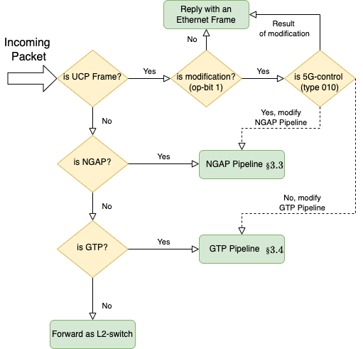
This section discusses the high-level view of our programmable data path and its control protocol, UCP. As shown in Figure 3.3, we handle three types of packets: (a) UCP, (b) NGAP, i.e., cellular control plane, and (c) GTP, i.e., cellular data plane. We define the UCP so that network administrators can modify the rules such as network security and get network data such as user-specified traffic monitoring. We further use UCP for switch-to-switch communication.
Figure 3.3 shows the packet-level processing at the programmable switches between RAN and the cellular core network. The data plane first checks the type of incoming packet to decide further processing. If it is a UCP frame (Ethernet Type ), the data plane checks its 8-bit CMI to understand the type of UCP frame. Table 3.2 shows the supported types of UCP frames, including their description and payload. The data plane finally replies with a UCP-reply frame if the received UCP frame requires a reply.
Suppose there is an incoming packet to the switch. If the switch identifies this packet as an NGAP packet (NGAP uses IP over SCTP with source or destination port ), it processes this packet using the NGAP pipeline described in Section 3.3. If it identifies the packet as a GTP packet (GTP uses IP over UDP with source port ), then the switch processes it using the GTP pipeline described in Section 3.4. Finally, if the packet does not match any of the aforementioned types, the switch behaves as an L2-switch, i.e., forwards the packet using the MAC table.
3.2.1 Unified Control Plane (UCP)
The UCP uses a layer-2 protocol that we define to manage the P4 switches between RAN and the core network. The control message is sent as Ethernet frames having an 8-bit control message identifier (CMI). The first 3 bits of CMI describe the operation type, and the following 5 bits describe the operation. The rest of the frame carries operation-related data. We implement the operations shown in Table 3.2.
3.2.1.1 Multi-Switch Communication
Many cellular networks contain hundreds or thousands gNBs, requiring multi-switch topology to connect them to the core networks.
| Operation Type | Op. ID | Description |
| 000 - Security | 00000 | Get all whitelisted IPv4s |
| 00001 | Get all blacklisted IPv4s | |
| 10000 | Add an IPv4 to whitelist | |
| 10001 | Add an IPv4 to blacklist | |
| 001 - Monitoring | 00000 | Get monitoring stats |
| 00001 | Get monitoring rule | |
| 00010 | Get number of monitoring rules | |
| 10000 | Add a monitoring rule (Specification as frame/packet header) | |
| 010 - 5G Control | 00000 | Get current number of UE |
| 10000 | Delete UE ID | |
| 011 - 5G Data | 10000 | Add UE IPv4 |
| 110 - gNB Control | 10000 | New TEID |
| 10001 | Remove TEID | |
| 10011 | Path to | |
| 111 - Reply | 00000 | Reply without modification |
| 10000 | Modification succeeded | |
| 10001 | Modification failed | |
| 10010 | Nexthop is updated |
In this section, we describe our interswitch protocol managing intra-cellular optimization. As we elaborate in Section 3.4, intra-cellular optimization allows certain UE within the same cellular network to communicate without sending packets to UPF. The packet forwarding is done within the P4 switches using the TEID of receiving UE to determine which gNB to forward. When a gNB receives a new TEID, it broadcasts the 32-bit TEID as a UCP frame with operation code as shown in Table 3.2. Our protocol uses Dijkstra’s shortest path algorithm to determine the next point of TEID, and we give the pseudocode in Figure 3.4 and Figure 3.5 for a switch and the UCP, respectively. UCP distributes the next-hop information in a centralized fashion by running Dijkstra’s algorithm. P4 switches thus only run the TEID matching algorithm to update their TEID registers. When a path update occurs on a switch after a piece of new information from the UCP, the switch sends an acknowledgment message with code back to the UCP.
On which has number of , , connected to it. Uses the data structures and Initially , on receive TEID from switch on receive NEXTHOP to if then unicast , 11110010, 111Reply: Nexthop Updated for on the switch . to UCP end if on new TEID from broadcast , 11010001, 222New TEID on the switch . to all switches
Run at UCP with ordered routing path on topology change compute for all pairs mark if is changed for do if then unicast (, 11010011, ) to end if end for on receive REPLY message store
3.3 The Cellular Control Plane
In addition to the cellular data plane packet processing, our architecture contains a cellular control plane packet processing within the same switch.
Our cellular control plane program is rather a proof-of-concept work that processes NGAP packets at the line rate. It filters the PDU establishment message between the UE and RAN and stores the UE IDs on the programmable switch. We implement a type of UCP message (with message code as seen in Table 3.2) to query the live UE data from the programmable data path.
3.4 The Cellular Data Plane
This section details the packet processing pipeline at the cellular data plane aiming to achieve URLLC latency targets, specifically on the N3 link, as shown in Figure 1.1. In addition to latency gains, our design empowers cellular networks to achieve monitoring up to the application layer with enhanced network security.
As next-generation cellular networks, including the 5G, target massive networks with increased in-network communication (e.g., industrial cellular networks), we aim to reduce the latency between users of the same cellular network. To this end, we propose a novel method, intra-cellular optimization, that allows an authorized set of users to communicate without involving UPF with the packet transfer. Thanks to the programmable switches that interconnect the gNBs and cellular core, the switches forward the GTP packets from known UE pairs back to the respective gNB. Intra-cellular optimization, therefore, significantly reduces the latency of the UE pairs. It further reduces the load on UPF and consequently improves the overall network performance in terms of latency and throughput. UCP allows network engineers to manage the authorization set at the programmable switches in real-time while actively updating the table with the TEID from the GTP packets matched with UE IP addresses. Further, UCP runs a centralized shortest-path routing algorithm between switches to distribute paths with TEID data so that switches can forward GTP packets to switch connecting to the respective gNB.
In addition to intra-cellular optimization, we implement a fine-grained network monitoring mechanism on the programmable switch and utilize UCP to poll real-time monitoring statistics. Finally, we design a fine-grained firewall with either whitelisting or blacklisting behavior (depending on the decision of default forwarding behavior). We implement our design in P4 to support IPv4, ICMP, TCP, UDP, and SCTP, yet our implementation can further be extended to support different types of network protocols.
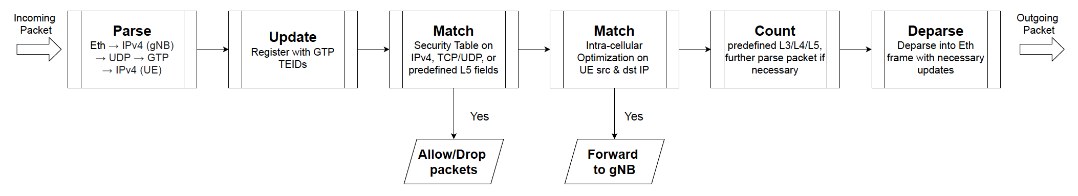
As shown in Figure 3.7, our packet processing pipeline supports GTPv2 packets that encapsulate IPv4 packets from the UE. We keep a mapping between UE IP addresses with their respective GTP downstream TEID, where the downstream is the GTP packet from gNB to UE. We use this map to determine destination gNB on intra-cellular optimization. The pipeline then examines the packet in terms of the security rules and takes the necessary actions, such as dropping the packet. If the pipeline does not drop the packet due to security rules, it applies the intra-cellular network optimization table, keeping the authorized UE IP addresses. In case of a hit on this table, the pipeline modifies the packet into a GTP downstream, updates the TEID, and forwards it to gNB with the respective UE (or another switch that connects to that gNB). Before forwarding the packet, the pipeline applies the monitoring rules on the decapsulated IP packet. The pipeline finally encapsulates the packet back to GTP and forwards it accordingly.
3.5 Mathematical Model of the Intra-Cellular Latency
In this section, we present the mathematical model that we design to evaluate the end-to-end latency of UE communication. We utilize our model in the evaluation section for the bigger cellular networks.
Definition 3.1 (Node).
A node is either (a) UE, (b) gNB, (c) a switch, (d) UPF.
Definition 3.2 (Network).
A network () is a graph of nodes, where the node types have the following limitations
-
(i)
UE (), can only be the first or the last node in the graph
-
(ii)
gNB () can only be in between UE and a switch
-
(iii)
a switch () cannot be connected to UE
-
(iv)
UPF () is one-and-only in a network, and it only connects to a switch
We use the following definitions from our preliminary work [38].
Definition 3.3 (Link).
A link is an undirected pair between two nodes ( and ), where . A link has a latency value .
Definition 3.4 (Path).
A path of and is the smallest (in terms of number of unique nodes) sub-network that connects and and contains the UPF node, that is, and connecting and , .
In addition to the path, we define an optimized path for intra-cellular optimization, as shown below.
Definition 3.5 (Optimized Path).
An optimized path of and is the smallest (in terms of number of unique nodes) sub-network that connects and and does not contain the UPF node, that is, and connecting and , .
Definition 3.6 (End-to-end Latency).
We define the path end-to-end latency ( of path ) as the sum of latency of each link in path . That is,
| (3.1) |
where and iff is UE or is UE.
The end-to-end latency without intra-cellular optimization for an optimized path is:
| (3.2) |
where is the switch latency between nodes . Similarly, the latency equation becomes as follows for an optimized path:
| (3.3) |
since the link to UPF from and another connection back from the UPF to are not in the the path.
Chapter 4 IMPLEMENTATION
This section gives the details of the implementation of our architecture that we introduced in Chapter 3. The implementation contains two parts: (a) Emulation: we have implemented a single switch topology with two gNBs (each having a single UE) with an open-source 5G core, Open5GS. We run the P4 code on BMV2, a P4 software switch, and deploy each gNB and the 5G core in individual virtual machines. This implementation aims to evaluate and demonstrate our architecture’s capabilities in a real 5G network and evaluate the latency gain. (b) Simulation: As we mentioned earlier, UCP can also run on multi-switch topologies. Due to the hardness of emulating multiple P4 software switches, we implement a Python simulator that simulates the switch behavior. We use this simulation implementation to evaluate the UCP under different switches and gNBs.
4.1 Emulation
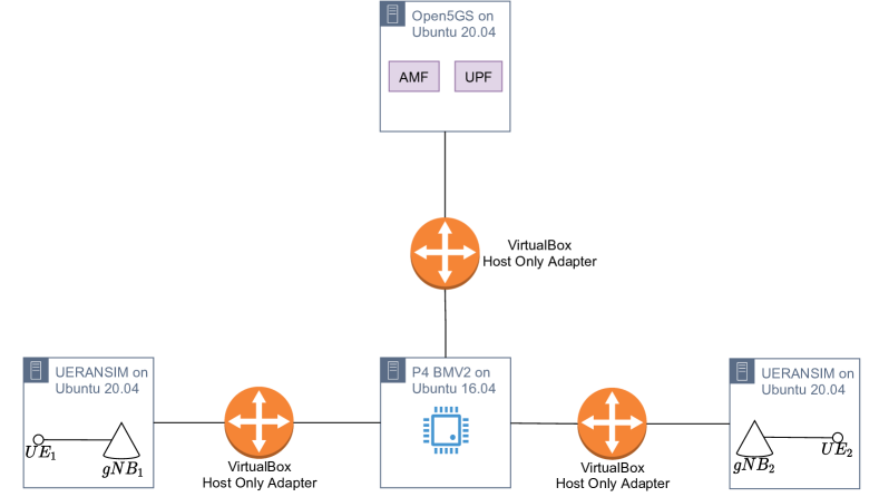
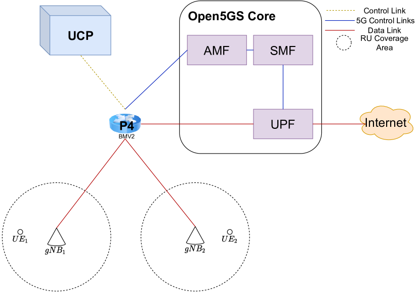
In the first part of our implementation, we design a 2-UE topology to demonstrate our programmable data path on a full 5G stack. We pick the P4’s behavioral model (BMV2) [41] software switch to run our pipeline written in P4 version 16 (P416 [42]). We pick Open5GS [43] for 5G stack that provides core network functions and UERANSIM [44] as the UE and RAN simulator, which provides RAN implementation including UE and gNBs. As depicted in Figure 4.1, we deploy two virtual machines (VM) where each runs a UE and gNB, another VM running Open5Gs, and one final VM that interconnects other VMs and deploys the P4 software switch on a MacBookPro with 16 GB RAM and an Intel i7 (4-cores) clocked at 2.9 GHz. We use Host-Only Adapter [45] as the network adapter between each VM. We use Ubuntu Server 20.04 [46] as the OS in each VM, except for the VM running P4, which has Ubuntu Server 16.04.
As our implementation works on top of software emulation, we evaluate the gain of intra-cellular optimization compared to traditional cellular network usage on the same topology. This is because BMV2 is instead a development tool that is not designed as a production-grade software switch, per its documentation. It is, therefore, logical to expect higher latency gains on a hardware P4 switch such as Tofino.
| VM | OS | v-CPU Cores | RAM |
| Open 5Gs | Ubuntu 20.04 | 1 | 3072 MB |
| UERANSIM (/) | Ubuntu 20.04 | 1 | 2048 MB |
| P4 BMV2 | Ubuntu 16.04 | 2 | 4096 MB |
4.1.1 P4 Implementation
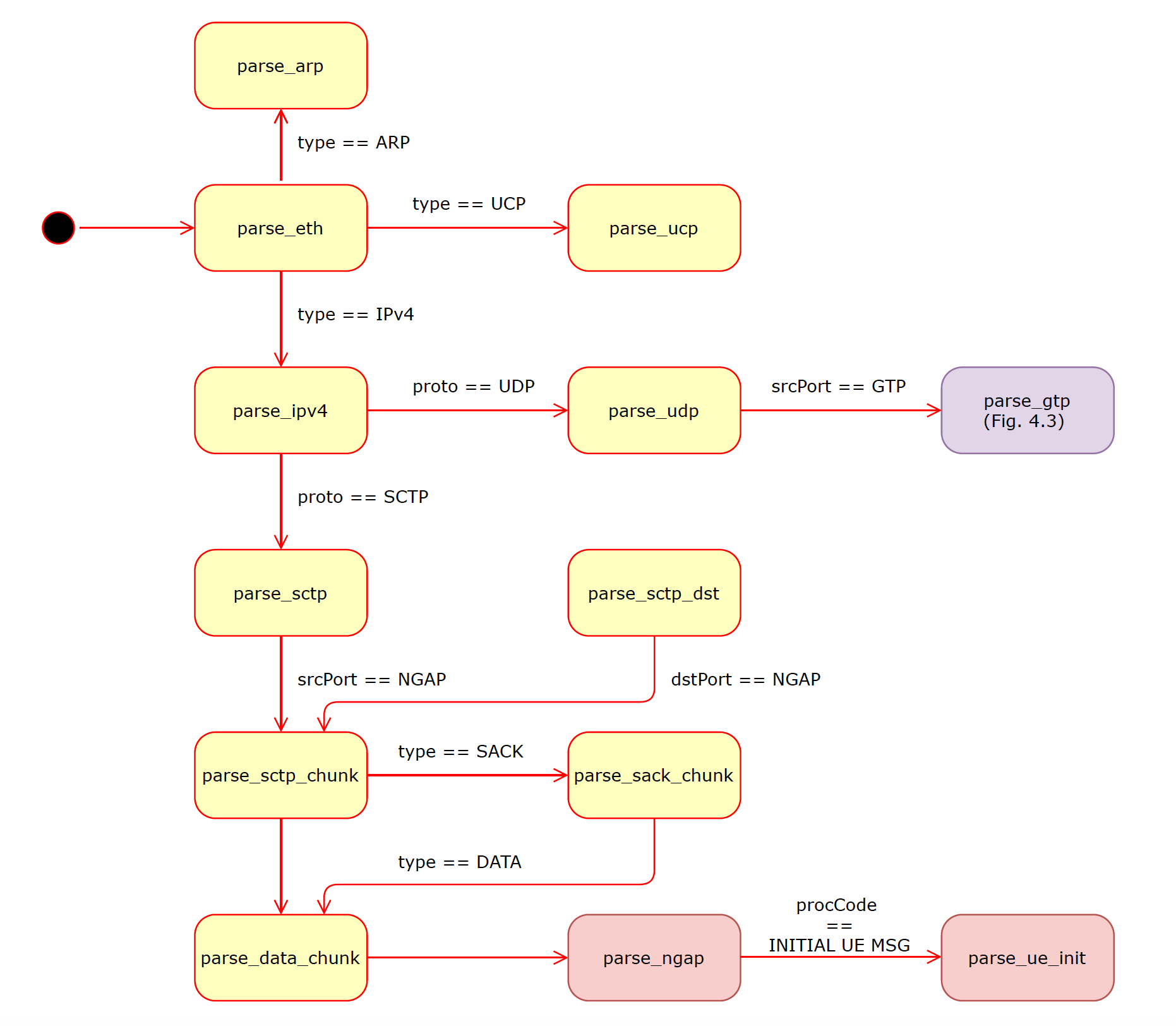
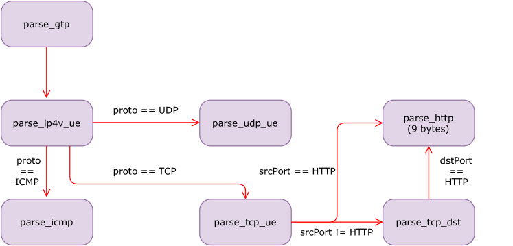
Our programmable data plane contains two parts: (a) A fine state machine (FSM) that parses the incoming packet’s headers as shown in Figure 4.2 and Figure 4.3, and (b) packet processing algorithm. We first parse the L2 (i.e., Ethernet) header and continue until the application layer (i.e., GTP and NGAP), depending on the content. For the cellular data packets (i.e., GTP), we also parse up to the IPv4 packet encapsulated into the GTP. Note that parsing of the encapsulated IPv4 packet can be modified depending on the user’s needs. The parsing FSM we use in our evaluation is shown in Figure 4.3.
P4 program runs the processing algorithm utilizing the headers that are parsed in the first stage as shown in Figure 4.4 after the packet header processing. The algorithm applies tables we define in Table 4.2 in order to update P4 registers (e.g., for counting) depending on the packet content. Note that our P4 program has an L2-switch behavior (i.e., MAC-based frame forwarding) for other types of packets as shown in Figure 3.3.
if ipv4_ue then apply table ipv4_downstream_teid apply table ipv4_in_network apply table ipv4_{in, out}_{wlist, blist} apply {tcp, udp}_{in, out}_ {wlist, blist} if tcp_ue then apply http_sensor and increment related counter end if else if ngap_init then add ngap_init.value to ue_ids list else if ucp then match on ucp.opId and take the related action in Table 3.2 end if
4.2 Multi-Switch Simulation
As our emulation implementation requires high computing resources, we develop a Python simulation to evaluate the performance of our system on larger topologies having multiple P4 switches. Our simulation implementation consists of four parts, namely: (a) topology generation, (b) route computation and TEID announcement, (c) UCP implementation, and (d) intra-cellular latency simulation.
| Table | Match |
| ngap_ue | ngap_ue_id |
| ipv4_down_teid | ipv4.src, ipv4_ue.dst (lpm111longest prefix match: matching with the most specific address [48].) |
| ipv4_in_network | ipv4.src, ipv4_ue.dst (lpm) |
| ipv4_{in, out}_{wlist, blist} | ipv4.{src, dst} (lpm) |
| {tcp, udp}_{in, out}_ {wlist, blist} | {tcp, udp}.{srcPort, dstPort} |
| http_sensor | http_ue.command |
4.2.1 Topology Generation
We randomly generate topologies with gNBs between up to 200 and 40 switches at maximum. Each gNB has at most 10 devices.
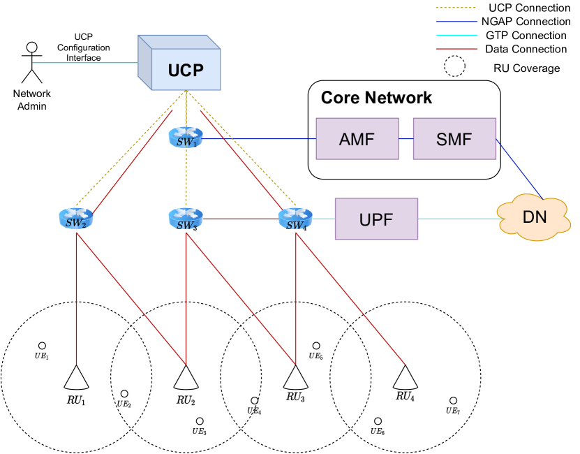
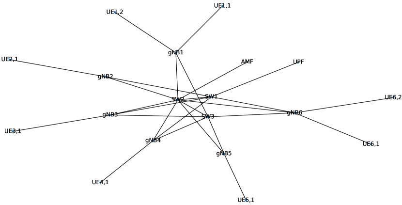
The UPF and AMF connect to a topology via separate P4 switches, as shown in Figure 4.5. An example topology generated by this algorithm is shown in Figure 4.6. We vary the switch-to-gNB ratio to evaluate the effect of the switch-to-gNB ratio on the end-to-end latency.
Given switch-to-gNB ratio (), number of switches (), and maximum gNB-to-UE ratio (). Use nodes an array of Node nodes where uniform() connect (, ) and (, ) pairs connect and , connect and , = uniform() connect and for a total of randomly generated unique pairs of
4.2.2 Route Computation and TEID Announcement
In the first part of our simulation, we implement the simulated behavior of each switch. We implement a Link State Routing (LSR) algorithm, inspired by the OSPF [49], between switches where each switch announces its link-state periodically. Similar to the routing, we have also implemented a TEID announcement algorithm where each switch announces the updates on its TEID table instantaneously. We evaluate the TEID distribution behavior in Section 5.2.1.
4.2.3 UCP Implementation
We run a process for each switch in the topology using the Python’s
multiprocessing [50] library. We further execute another process that runs as the UCP controller. Each switch process runs a simulation version of the P4 main loop we describe above, where a switch process can (a) receive and create UCP messages, (b) process data messages from and to the other switches.
4.2.4 Intra-Cellular Latency Evaluation Simulation
Due to computational resource limitations, we design our emulation platform with two pairs of gNB-UE. On the other hand, real-world cellular applications can contain many more devices and gNBs, requiring multiple programmable switches to interconnect them. To demonstrate our design’s performance on a large-scale topology, we implement a Python simulation of the switches where each switch runs the algorithms in Figure 3.4 as a process based on Python’s multiprocessing library. We then implement another process that is responsible for the UCP and based on the algorithms in Figure 3.5. We use the mathematical model of latency in Section 3.5 to normalize the latency values we gather from the simulation.
Chapter 5 EVALUATION
In this section, we first present the evaluation results using the emulation defined in Section 4.1. With our emulation platform, we evaluate (a) latency improvement with the intra-cellular optimization, (b) NGAP processing at the data plane using P4, (c) in-network security capabilities, and (d) fine-grained network monitoring. We, then, discuss the evaluation results with our simulation focusing on multi-switch topologies: (a) TEID announcement and route computation with UCP, and (b) latency improvement with intra-cellular optimization. We finally conclude this chapter with a comparison between latency results and the mathematical model of latency described in Section 3.5.
5.1 Evaluation with Cellular Network Emulation
Figure 5.1 shows that we use a topology with a single P4 switch that connects the gNBs to each other and the 5G cellular network. We describe the details of the implementation in Section 4.1. We use the same topology for all experiments in this section except for the last one, where we define a slightly different topology that includes connection to the outside of the cellular network.
5.1.1 Intra-Cellular Latency Evaluation
The devices on a cellular network use a dedicated network function (e.g., UPF in 5G) to reach to the outside networks (e.g., the Internet). Moreover, this requirement is still valid for two users in the same network, as the RAN passes data path packets (tunneled using GTP) between UE and respective cellular function. Unfortunately, this creates an additional delay for the users in the same cellular networks. With the emergence of the newer use cases for cellular networks such as industrial networks, this problem further exacerbates since many devices in such networks communicate with other devices within the network.
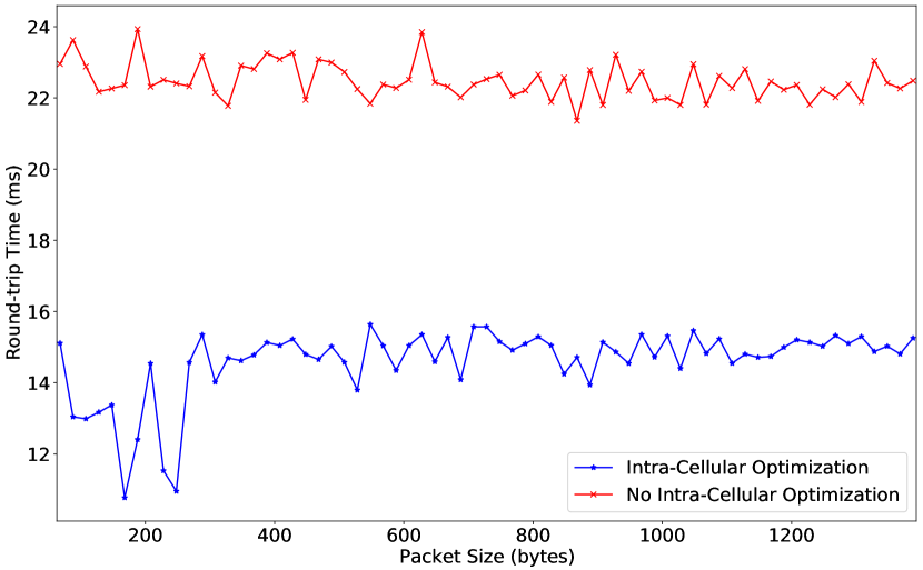
Moreover, network administrators in such private networks have control over the devices (e.g., IIoT sensors in an industrial cellular network); therefore, they can control or pre-authorize the devices for network usage and make session management controls for such devices ”unnecessary”. With such considerations in mind, we design architecture in programmable switches where we utilize a TCAM table to hold the IP addresses and GTP TEIDs to forward GTP packets from known UE to the relative gNB instead of sending them to the UPF. We discuss the details of our design in Section 3.4. As shown in Figure 5.2, our design can decrease latency by a factor of two in most of the cases with an average of 1.5x. In addition, our experiment shows that our system can work on packet sizes smaller than the Ethernet’s conventional MTU of 1500 bytes. This limitation can be avoided by modifying our implementation to handle IP packets spanned to multiple Ethernet Frames. An earlier version of this experiment appeared in our preliminary work [39].
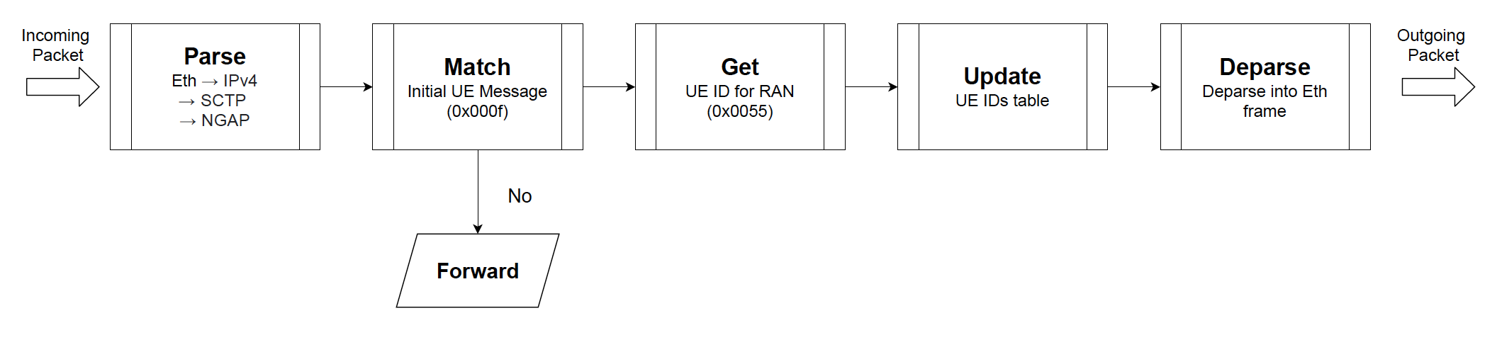
5.1.2 NGAP Processing
In addition to the GTP processing pipeline, we design an NGAP processing pipeline at the programmable data plane to parse the NGAP packets. It is relatively simple, matching initial UE messages and storing the UE IDs in a P4 register. Our design is a proof-of-concept demonstrating a complex protocol such as NGAP could be processed at the switch at line speed. Consequently, in this experiment, we demonstrate the scenario where numerous UE registers send the initial UE message, and then we poll the registered UE IDs using UCP.
Table 5.1 shows the average register retrieval time via UCP with respect to poll interval, where we run 500 experiments for each poll interval. We see that the average interval time is between 29 - 68 ms, and the higher poll interval causes the higher average time.
| Poll Frequency | Average Processing Time (ms) |
| 0.1 Hz | 67.4 |
| 1 Hz | 65.6 |
| 10 Hz | 63.4 |
| 100 Hz | 57.2 |
| 1000 Hz | 47.2 |
| Hz | 29.2 |
5.1.3 Security Evaluation
One aspect of our framework is network security. To this end, we implement a network firewall dedicated to UE traffic tunneled via GTP. The firewall uses the TCAM tables of P4 and is updated via UCP in real-time. While our design works at the line speed, it reduces the hardware cost of cellular networks as it can the traditional firewalls.
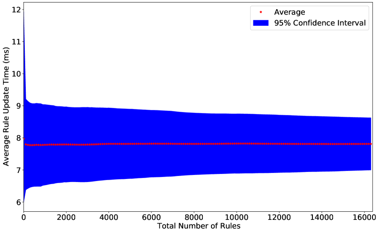
In this experiment, we evaluate the performance of our UCP implementation and P4-software switch. We update the security rules and measure the rule update time considering the total number of rules on the switch. We measure the rule update time from the UCP input until the rule’s effect is seen on the dataplane.
We implement a Python script to create HTTP servers with incremental port numbers, and it marks as the rule update when the connection to the server is broken, as we send ”deny” rules with the specific port numbers. As shown in Figure 5.3, We found no significant evidence indicating a relation between the total number of rules and average rule update time. We measure the average rule update time less than 10 ms when the total number of rules exceeds 100 with a 95% confidence interval.
5.1.4 Monitoring Evaluation
This experiment adds IP, TCP, and HTTP counters for UE traffic via GTP. With the HTTP counter, we evaluate a scenario with IoT sensors. Each sensor sends a 2-byte heartbeat signal containing their ID. Our HTTP counter counts the number of heartbeat signals for each sensor, and we poll the counter status of each sensor via UCP. We also consider a TCP traffic with iPerf3 [52] between a server in Google Cloud and the UE, where the UE and IoT sensors are on the same cellular network. We show the whole evaluation topology in Figure 5.4.
We measure the throughput of the traffic between the UE and the server with respect to the polling interval of the HTTP counter via UCP. Table 5.2, shows that the traffic is significantly affected for less than 10 ms polling intervals.
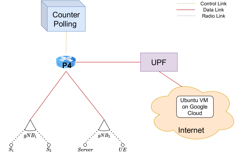
As we perform our evaluation on the BMV2 software switch, which runs on the same machine running the 5G network, the results with polling intervals shorter than 10 ms are insignificant. Further, a 10 ms polling interval for such a counter is unrealistic as many IoT devices have heartbeat intervals much higher than 10 ms.
| UCP Poll Frequency | Throughput |
| no polling (0 Hz) | 100.0% |
| 1 Hz | 98.8% |
| 10 Hz | 96.4% |
| 100 Hz | 93.3% |
| 1000 Hz | 89.1% |
| 10000 Hz | 84.2% |
| no interval ( Hz) | 74.5% |
5.2 Multi-Switch Simulation
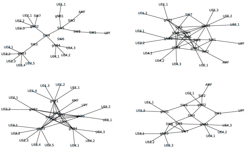
Due to resource constraints, we evaluate the multi-switch topology with a higher number of gNBs by implementing a Python simulation. The simulation runs for any arbitrary topology where P4 switches connect gNBs to AMF and UPF. We evaluate (a) the route computation and TEID advertisement performance at switches, and (b) the end-to-end communication latency with intra-cellular optimization and without it. Figure 5.5 shows some of the network topologies we use in the experimentation. Note that all of the topologies are randomly generated using Algorithm 4.5.
5.2.1 Route Computation and TEID Announcement
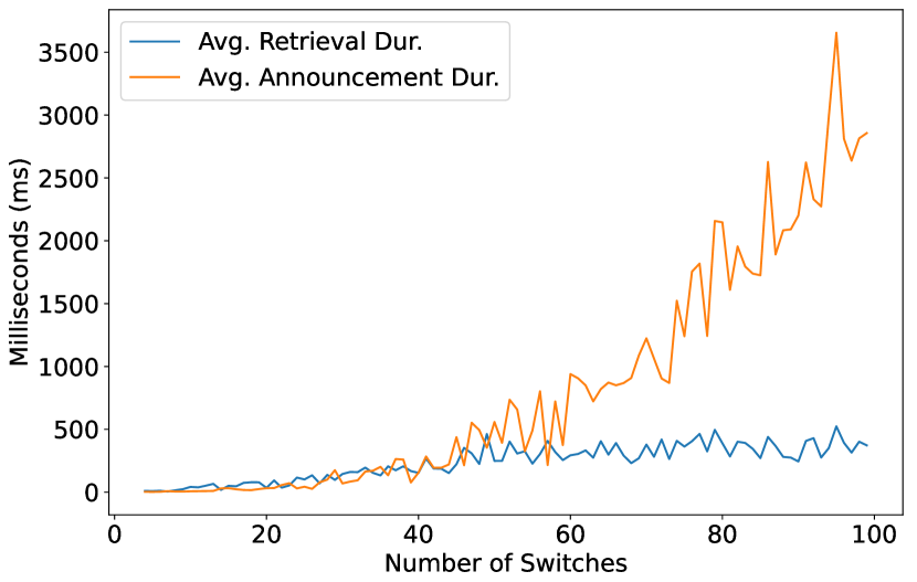
In this experiment, we test the implementation of TEID announcement algorithms that are deployed at the programmable switches shown in Figure 3.4.
We see a direct proportion between the number of switches and average retrieval and announcement durations; the larger network means a higher average distance between any pair of nodes. The results, therefore, suggest 250 ms or smaller average advertisement and retrieval times on networks containing 20 or fewer switches. For example, in a border case network with 100 switches, the average advertisement time reaches 1500 ms while the average retrieval time is around 500 ms.
5.2.2 Intra-Cellular Latency Evaluation on Simulation
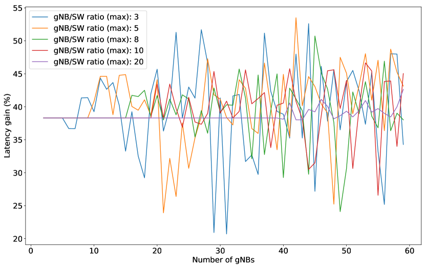
In this set of experiments, we evaluate the intra-cellular latency optimization behavior on larger topologies with multiple P4 switches using the Python simulation we described in Section 4.2. As shown in Figure 5.7, we can achieve latency gain between 20% and 50%, where the average is between 35% and 40%. The results show that the higher gNB/SW ratio leads to more stable latency gain with respect to the number of gNBs as the higher gNB/SW ratio leads to less SW, i.e., smaller networks. We see similar results yet with less latency gain because of the cases where the intra-cellular optimization is not advantageous as it is on a topology with two gNBs.
Chapter 6 CONCLUSION
This thesis presents an SDN architecture for the next-generation cellular networks to achieve URLLC, explicitly targeting networks with a high frequency of intra-network communication. It utilizes the programmable data planes between cellular core and radio network, and it presents the concept of intra-cellular optimization, that allows pre-authorized in-network devices to communicate without the requirement of cellular control signals. Further, this thesis introduces a novel control structure, Unified Control Plane (UCP), on top of the Ethernet Layer with an adapted version of UE information distribution link-state routing. We implement the architecture in this thesis on the P4 programming language for programmable data planes with a 5G implementation and a UE/RAN simulator. We further implement a simulation framework to evaluate the performance of our design in large-scale topologies on Python. We show that the concept of intra-cellular optimization can achieve latency reduction up to 2x, whereas it can tremendously increase the network security and monitoring capabilities compared to traditional cellular networks while having a ten-millisecond level of control latency.
References
- 1. Korhonen, J., O. Aalto, A. Gurtov and H. Laamanen, “Measured Performance of GSM HSCSD and GPRS”, IEEE International Conference on Communications, Vol. 5, Helsinki, Finland, 2001.
- 2. Tan, W. L., F. Lam and W. C. Lau, “An Empirical Study on The Capacity and Performance of 3G Networks”, IEEE Transactions on Mobile Computing, Vol. 7, No. 6, pp. 737–750, 2008.
- 3. Krapichler, C., “LTE, HSPA and Mobile WiMAX A Comparison of Technical Performance”, Media, pp. 1–31, 2007.
- 4. Li, Z., H. Shariatmadari, B. Singh and M. A. Uusitalo, “5G URLLC: Design Challenges and System Concepts”, Proceedings of the International Symposium on Wireless Communication Systems, Vol. 2018-August, Lisbon, Portugal, 2018.
- 5. “TS 123 501 - V15.2.0 - 5G; System Architecture for The 5G System (5GS) (3GPP TS 23.501 Version 15.2.0 Release 15)”, European Telecommunications Standards Institute (ETSI), 2018.
- 6. ITU-T, “The Tactile Internet”, https://www.itu.int/dms\_pub/itu-t/oth/23/01/T23010000230001PDFE.pdf, accessed on August 02, 2022.
- 7. Bifulco, R. and G. Retvari, “A Survey on The Programmable Data Plane: Abstractions, Architectures, and Open Problems”, IEEE International Conference on High Performance Switching and Routing, HPSR, Bucharest, Romania, 2018.
- 8. Bosshart, P., D. Daly, G. Gibb, M. Izzard, N. McKeown, J. Rexford, C. Schlesinger, D. Talayco, A. Vahdat and Varghese, “P4: Programming Protocol-Independent Packet Processors”, ACM Special Interest Group on Data Communication Computer Communication Review, Chicago, IL, 2014.
- 9. “TS 123 501 - V16.6.0 - 5G; System Architecture for The 5G System (5GS) (3GPP TS 23.501 Version 16.6.0 Release 16)”, European Telecommunications Standards Institute (ETSI), 2020.
- 10. Popovski, P., K. F. Trillingsgaard, O. Simeone and G. Durisi, “5G Wireless Network Slicing for eMBB, URLLC, and mMTC: A Communication-Theoretic View”, Ieee Access, Vol. 6, pp. 55765–55779, 2018.
- 11. Jiang, W., B. Han, M. A. Habibi and H. D. Schotten, “The Road Towards 6G: A Comprehensive Survey”, IEEE Open Journal of the Communications Society, Vol. 2, pp. 334–366, 2021.
- 12. Habibi, M. A., M. Nasimi, B. Han and H. D. Schotten, “A Comprehensive Survey of RAN Architectures Toward 5G Mobile Communication System”, IEEE Access, Vol. 7, pp. 70371–70421, 2019.
- 13. Anand, A., G. de Veciana and S. Shakkottai, “Joint Scheduling of URLLC and eMBB Traffic in 5G Wireless Networks”, IEEE/ACM Transactions on Networking, Vol. 28, No. 2, pp. 477–490, 2020.
- 14. Li, J. and X. Zhang, “Deep Reinforcement Learning-Based Joint Scheduling of eMBB and URLLC in 5G Networks”, IEEE Wireless Communications Letters, Vol. 9, No. 9, pp. 1543–1546, 2020.
- 15. Mutalemwa, L. C. and S. Shin, “A Classification of the Enabling Techniques for Low Latency and Reliable Communications in 5G and Beyond: AI-Enabled Edge Caching”, IEEE Access, Vol. 8, pp. 205502–205533, 2020.
- 16. Le, T. K., U. Salim and F. Kaltenberger, “An Overview of Physical Layer Design for Ultra-Reliable Low-Latency Communications in 3GPP Releases 15, 16, and 17”, IEEE Access, Vol. 9, pp. 433–444, 2021.
- 17. Ray, J. K., A. Singh, Q. M. Alfred, S. Shome and R. Bera, “5G URLLC Communication System with Cognitive Radio and Frequency Diversity Reception for Improving Reliability in Smart Factory E-cranes operation”, IEEE MTT-S International Microwave and RF Conference (IMARC), Mumbai, India, 2019.
- 18. Yogapratama, A. S. and M. Suryanegara, “Dealing with the Latency Problem to Support 5G-URLLC: A Strategic View in the Case of An Indonesian Operator”, 2nd International Conference on Broadband Communications, Wireless Sensors and Powering (BCWSP), Jakarta, Indonesia, 2020.
- 19. Jayaweera, N., D. Marasinghe, N. Rajatheva and M. Latva-Aho, “Factory Automation: Resource Allocation of An Elevated LiDAR System with URLLC Requirements”, 2nd 6G Wireless Summit (6G SUMMIT), Porto, Portugal, 2020.
- 20. McKeown, N., T. Anderson, H. Balakrishnan, G. Parulkar, L. Peterson, J. Rexford, S. Shenker and J. Turner, “OpenFlow: Enabling Innovation in Campus Networks”, Special Interest Group on Data Communication (SIGCOMM) Computuer Communication Reviews, Vol. 38, No. 2, Mar. Seattle, WA, 2008.
- 21. Kfoury, E. F., J. Crichigno and E. Bou-Harb, “An Exhaustive Survey on P4 Programmable Data Plane Switches: Taxonomy, Applications, Challenges, and Future Trends”, IEEE Access, 2021.
- 22. Sun, S., L. Gong, B. Rong and K. Lu, “An Intelligent SDN Framework for 5G Heterogeneous Networks”, IEEE Communications Magazine, Vol. 53, No. 11, pp. 142–147, 2015.
- 23. Prados-Garzon, J., O. Adamuz-Hinojosa, P. Ameigeiras, J. J. Ramos-Munoz, P. Andres-Maldonado and J. M. Lopez-Soler, “Handover Implementation in A 5G SDN-based Mobile Network Architecture”, IEEE International Symposium on Personal, Indoor and Mobile Radio Communications (PIMRC), Valencia, Spain, 2016.
- 24. Ricart-Sanchez, R., P. Malagon, J. M. Alcaraz-Calero and Q. Wang, “P4-NetFPGA-based Metwork Slicing Solution for 5G MEC Architectures”, ACM/IEEE Symposium on Architectures for Networking and Communications Systems, Cambridge, UK, 2019.
- 25. Zaidi, Z., V. Friderikos, Z. Yousaf, S. Fletcher, M. Dohler and H. Aghvami, “Will SDN Be Part of 5G?”, IEEE Communications Surveys Tutorials, Vol. 20, No. 4, pp. 3220–3258, 2018.
- 26. Eichhorn, F., M. Corici, T. Magedanz, P. Du, Y. Kiriha and A. Nakao, “SDN Enhancements for The Sliced, Deep Programmable 5G Core”, 13th International Conference on Network and Service Management (CNSM), pp. 1–4, Tokyo, Japan, 2017.
- 27. Costa-Requena, J., A. Poutanen, S. Vural, G. Kamel, C. Clark and S. K. Roy, “SDN-Based UPF for Mobile Backhaul Network Slicing”, European Conference on Networks and Communications (EuCNC), Ljubljana, Slovenia, 2018.
- 28. Peters, S. and M. A. Khan, “Anticipatory Session Management and User Plane Function Placement for AI-Driven Beyond 5G Networks”, Procedia Computer Science, Vol. 160, pp. 214–223, 2019.
- 29. Peters, S. and M. A. Khan, “Anticipatory User Plane Management for 5G”, IEEE 8th International Symposium on Cloud and Service Computing (SC2), Paris, France, 2018.
- 30. Paul, S., “Discover 5G Core Network Functions Compared to 4G LTE”, https://www.linkedin.com/pulse/discover-5g-core-network-functions-compared-4g-lte-paul-shepherd, accessed on August 02, 2022.
- 31. “TS 138 423 - V16.3.0 - 5G; NG-RAN; Xn Application Protocol (XnAP) (3GPP TS 38.423 Version 16.3.0 Release 16)”, European Telecommunications Standards Institute (ETSI), 2020.
- 32. “TS 138 415 - V16.1.0 - 5G; NG-RAN; PDU Session User Plane Protocol (3GPP TS 38.415 Version 16.1.0 Release 16)”, European Telecommunications Standards Institute (ETSI), 2020.
- 33. “TS 123 502 - V16.5.0 - 5G; Procedures for The 5G System (5GS) (3GPP TS 23.502 Version 16.5.0 Release 16)”, European Telecommunications Standards Institute (ETSI), 2020.
- 34. “TS 138 300 - V16.2.0 - 5G; NG; NR and NG-RAN Overall Description; Stage-2 (3GPP TS 38.300 Version 16.2.0 Release 16)”, European Telecommunications Standards Institute (ETSI), 2020.
- 35. “General Packet Radio Service (GPRS); GPRS Tunnelling Protocol (GTP) Across The Gn and Gp Interface”, 3rd Generation Partnership Project (3GPP), 2020, https://portal.3gpp.org/desktopmodules/Specifications/SpecificationDetails.aspx?specificationId=1595, version 16.0.0.
- 36. “3GPP Evolved Packet System (EPS); Evolved General Packet Radio Service (GPRS) Tunnelling Protocol for Control Plane (GTPv2-C); Stage 3”, 3rd Generation Partnership Project (3GPP), 2020, Version 16.7.0.
- 37. “Architecture Enhancements for Control and User Plane Separation of EPC Nodes ”, 3rd Generation Partnership Project (3GPP), September 2020, version 16.2.0.
- 38. Gökarslan, K. and T. Tugcu, “Velox: Next-Generation Industrial Cellular Networks With Programmable Data Planes”, IEEE International Black Sea Conference on Communications and Networking (BlackSeaCom), Sofia, Bulgaria, 2022.
- 39. Gökarslan, K., Y. S. Sandal and T. Tugcu, “Towards a URLLC-Aware Programmable Data Path with P4 for Industrial 5G Networks”, IEEE International Conference on Communications Workshops (ICC Workshops), Montreal, Canada, 2021.
- 40. “Oracle VM VirtualBox”, http://virtualbox.org/, accessed on August 02, 2022.
- 41. “P4 Behavioral Model”, https://github.com/p4lang/behavioral-model, accessed on August 02, 2022.
- 42. “P4-16 Language Specification”, https://p4.org/p4-spec/docs/P4-16-v1.0.0-spec.html, accessed on August 02, 2022.
- 43. “Open5GS”, https://github.com/open5gs/open5gs, accessed on August 02, 2022.
- 44. “UERANSIM”, https://github.com/aligungr/UERANSIM, accessed on August 02, 2022.
- 45. “VirtualBox Virtual Networking”, https://www.virtualbox.org/manual/ch06.html, accessed on August 02, 2022.
- 46. “Canonical Ubuntu”, https://ubuntu.com/, accessed on August 02, 2022.
- 47. Fielding, R. and R. J., “RFC 7230 - Hypertext Transfer Protocol (HTTP/1.1): Message Syntax and Routing”, 2014.
- 48. “Longest prefix match - Microsoft Academic”, https://academic.microsoft.com/topic/50363770/publication, accessed on August 02, 2022.
- 49. Moy, J., “RFC 2328 - OSPF Version 2”, 1998.
- 50. “Multiprocessing”, https://docs.python.org/3/library/multiprocessing.html, accessed on August 02, 2022.
- 51. “Ping”, https://man7.org/linux/man-pages/man8/ping.8.html, accessed on August 02, 2022.
- 52. “iPerf”, https://iperf.fr/, accessed on August 02, 2022.