Haptic search with the Smart Suction Cup on adversarial objects
Abstract
Suction cups are an important gripper type in industrial robot applications, and prior literature focuses on using vision-based planners to improve grasping success in these tasks. Vision-based planners can fail due to adversarial objects or lose generalizability for unseen scenarios, without retraining learned algorithms. We propose haptic exploration to improve suction cup grasping when visual grasp planners fail. We present the Smart Suction Cup, an end-effector that utilizes internal flow measurements for tactile sensing. We show that model-based haptic search methods, guided by these flow measurements, improve grasping success by up to 2.5x as compared with using only a vision planner during a bin-picking task. In characterizing the Smart Suction Cup on both geometric edges and curves, we find that flow rate can accurately predict the ideal motion direction even with large postural errors. The Smart Suction Cup includes no electronics on the cup itself, such that the design is easy to fabricate and haptic exploration does not damage the sensor. This work motivates the use of suction cups with autonomous haptic search capabilities in especially adversarial scenarios.
Index Terms:
Vacuum gripper, Tactile sensing, Bin-picking, Soft robot application, Sensor-based controlI Introduction
Vacuum grippers, or suction grippers, are widely used in industry for simple pick and place operations. Relying on negative internal pressure that forms when sealed against a surface, the suction gripper can gently handle an object without applying squeezing force, which allows an astrictive handling of various types of objects. If the item to be grasped is smooth and well modelled, as in manufacturing lines, the gripper can repeatably and predictably handle it with high reliability. However, for grasping in unstructured environments, e.g., in e-commerce warehouses, objects vary dramatically and present many different surface conditions that may or may not be easy to visually perceive or grip with a suction cup. Careful planning of grasp contact location is therefore important, and methods for doing so have been widely studied for the past few years. While there have been successful demonstrations of versatile suction grasp planners, these methods often rely on vision, which may not capture fine object details of the geometry and lead to suction failure. Moreover, pre-trained models are typically specific to certain suction cup and camera configurations, making it challenging to transfer these methods to different hardware setups without retraining. Time-consuming retraining currently presents a barrier to adoption.
To address these challenges, we propose the use of autonomous haptic search – or the repositioning of the cup using contact measurements – to supplement vision in suction grasping. This new approach leverages pre-trained vision-based grasp planners to obtain an approximate solution before then fine-tuning the pose after contact occurs until the grasp succeeds. For this method to be effective, we assume that a successful grasp point is close to the pre-trained planner’s solution even when errors emerge, as the planner already considers key factors of graspability such as the object’s weight distribution and the suction seal formation of a similar suction cup. To adjust the contact location, we use haptic exploration driven by flow-based tactile sensors on our Smart Suction Cup, first presented in [1]. This design has the advantage of no electronics embedded in the cup itself, but remote sensors can still provide valuable information about local suction leakages to overcome grasp failures.
I-A Overview
Section II provides a review of related works. In Section III, the Smart Suction Cup is described along with computational fluid dynamics models to demonstrate the expected signals; this design and flow analysis was previously presented in our prior work [1]. In the current work, we evolve this concept substantially beyond the prior work by now introducing and implementing autonomous haptic search. Section IV presents our new proposed haptic search algorithm that utilizes the flow readings to improve grasping on adversarial objects. Experimental setup and procedures are described in Section V, including both sensor characterization on primitive fixed objects and a bin-picking task with loose adversarial objects. Section VI presents the results of these experiments; overall, we find that the use of the Smart Suction Cup haptic algorithm provides useful controller estimates and more successful grasping. Discussed in Section VII, the model-based haptic exploration encounters failure modes that can be further improved in future work.
The contributions of this paper are as follows:
-
1.
Presentation and characterization of the first Smart Suction Cup that can sense local suction seal leakage on flat and curved surfaces by using remote pressure sensors.
-
2.
Design of a suitable model-based haptic search controller using tactile sensing feedback to improve suction seal in real time.
-
3.
Bin-picking experiments to evaluate performance across adaptive control algorithms with comparison to an existing vision-based grasp planner.
II Related works
II-A Suction grasp planning using vision
One major challenge in suction grasping is how to plan a contact location. Examples of planning methods include the heuristic search for a surface normal[2] and neural network training of grasp affordance using binary success labels[3]. Wan et al. (2020) use CAD model meshes to plan a grasp resisting gravitational wrench[4], and Dex-Net 3.0 learns the best suction contact pose from a point cloud considering both suction seal formation and gravitational wrench resistance[5]. Using a similar approach to Dex-Net, Cao et al. (2021) built a larger suction grasp dataset including RGB images and annotations of a billion suction points[6]. Using physics simulation, Shao et al. (2019) demonstrated a self-supervised learning method that finds suction grasp policies from RGB-D images for cluttered objects[7], and Cao et al. (2022) improved it by implementing dense object descriptors[8]. These aforementioned methods rely on RGB or depth sensors, which may not perceive fine details critical to suction success, e.g., texture, rugosity, porosity, etc. Vision can also become occluded in cluttered environments and heavily distorted with reflective or transparent objects.
II-B Suction cup tactile sensors
Prior tactile sensors designed for use in suction cups provide partial information about object properties and vacuum sealing state. Researchers employ strain sensors on a suction cup by coating PEDOT [9] or carbon nanotube [10], or by installing microfluidic channels filled with carbon grease [11]. These strain sensors measure suction deformation during surface contact, estimating the compression forces and load distributions of suction cups [9], surface angles and stiffness [11], and object weight and center of gravity [10]. Alternatively, the contact of the suction cup can be measured indirectly by proximity sensors, including a capacitive base plate [12], inserted fiber optic cable [13], and micro-LIDAR [14]. However, these methods provide information about the cup deformation and surface proximity, which may not always correspond to a suction seal formation that is subject to fine local geometry and porosity. For direct contact sensing, Muller et al. (2017) report a thin pressure sensor array attached to the suction cup lips, measuring the distributed contact pressures [15]. However, the sensor film on the contact layer may weaken the suction seals.
Another straightforward approach is to monitor the internal vacuum pressure of the suction cup as a discrete measure of suction sealing, as in [16]. However, this prior implementation method does not localize the source of a leak around the lip’s edge or measure local surface geometry, which is critical for adaptive haptic exploration for a better grasp.
II-C Adaptive Regrasping using Tactile Sensing
Robust grasping in real-world scenarios has driven research in adaptive regrasping using tactile sensing. Due to uncertainties in vision systems and difficulties capturing detailed object features, tactile sensors are employed to detect contact information and guide improvements in response to unsuccessful grasps. Adaptive regrasp research has predominantly focused on friction-based grippers rather than suction grippers. Simple regrasping approaches include increasing grasp forces or grasp impedance upon detection of perturbations, such as external forces causing slips[17, 18]. For multi-finger grippers, researchers have demonstrated finding better grasping points through finger gaiting [18]. These methods primarily aim to improve handling or increase the stability of objects already held by the gripper. In object-picking processes, deep learning or reinforcement learning techniques have been employed to process complex tactile sensor data. Chebotar et al. (2016) used a multi-finger gripper with a BioTac sensor to demonstrate regrasping of a simple cylindrical object; they analyzed complex spatiotemporal tactile sensor information with PCA and learned a regrasp policy to update the pose[19]. Reinforcement learning was also used to learn hand grasping and regrasping policies in simulation, which are then effectively transferred to real robots [20]. For parallel jaw grippers, vision-based tactile sensors, such as Gelsight, have been used[21, 22]. In [21], the researchers trained a grasp quality metric from a given tactile image and simulated possible image shifts to guide the best regrasping policy. In [22], they directly trained for the best action to achieve the highest grasp success, which could be either a regrasp or pick.
The majority of the approaches mentioned above rely on tactile sensing information processed by deep learning or reinforcement learning algorithms. These methods can be unintuitive and may require significant training data for generalization. These approaches may involve fully reopening the gripper during regrasp actions, which can be time-consuming. Moreover, theses approaches may not be applicable to suction grasping due to differences in grasping mechanisms. In the following sections, we will present a physics- or intuition-based regrasping controller for suction cup grippers, enabling generalization without requiring extensive training data. Our controller operates without losing contact, potentially reducing operation times. To our knowledge, no existing literature addresses adaptive regrasping for suction cup grippers.
III The Smart Suction Cup
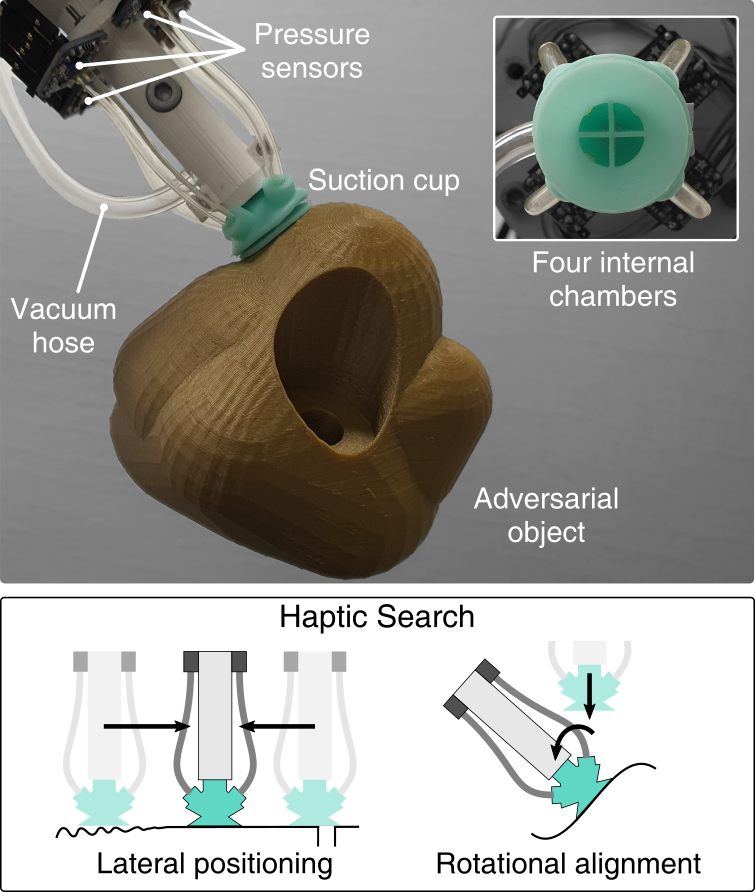
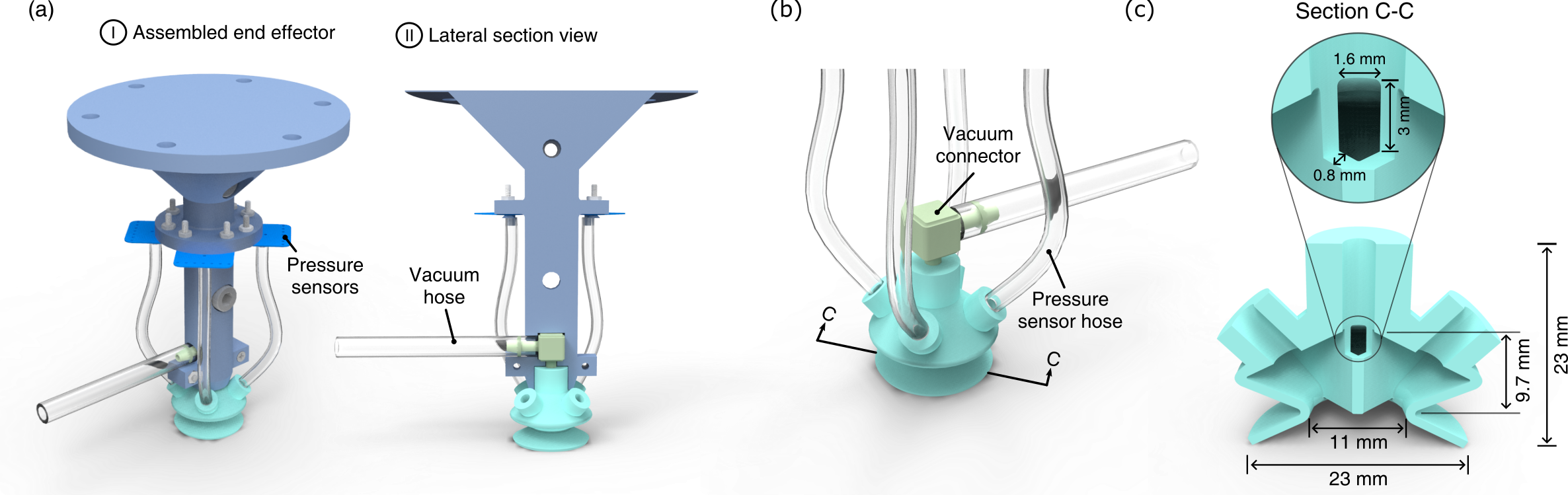
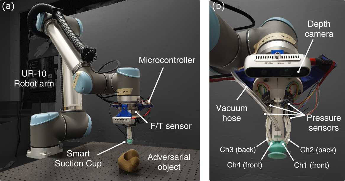
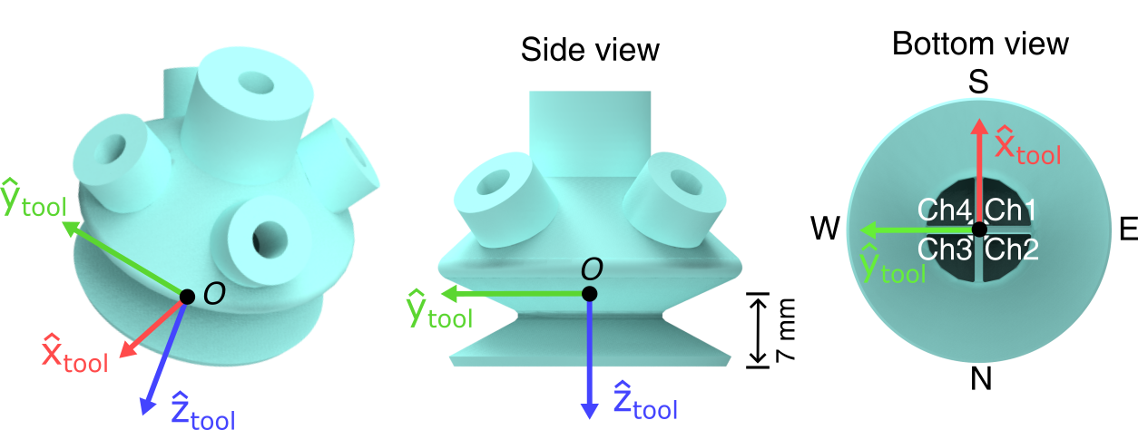
The Smart Suction Cup utilizes internal airflow estimates to monitor local contact conditions. Internal wall structures separate the internal cavity of the suction cup into four chambers (Fig. 1) – one for each cardinal direction. Overall suction airflow is therefore separated between each chamber and the pressure sensor connected to each chamber provides an estimate of the local flow rate. We implement the wall structure inside a single-bellows suction cup for its versatility on different curvatures and orientations of objects. The internal wall structure only spans the proximal portion of the suction cup, in order to maintain typical flexibility, deformation and seal formation at the distal lip. As shown in Fig. 3a-b, the suction cup is mounted to an end effector fixture piece and connected with pressure transducers and a single vacuum hose with pressure regulation. For experimental trials, this end effector is integrated with a universal robot arm. Dimensions and internal geometry of the compliant cup are shown in Fig. 3c. A single prototype is used throughout experimental testing, without incurring damage or needing replacement.
III-A Fabrication
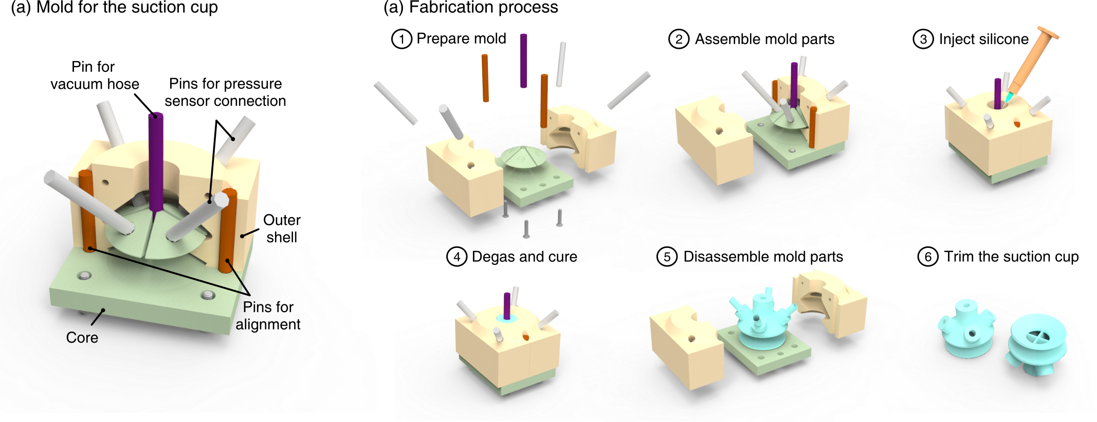
We fabricate this 3D rubber structure including the chamber walls as in Fig. 3, with a single-step casting of silicone rubber. The casting mold comprises three parts, two outer shells and one core, that are 3D printed using an SLA 3D printer (Formlabs, Form2). These are assembled together using stainless steel dowel pins and bolts. To ensure the clean casting of the thin internal wall structures (0.8 mm thick), we used a syringe with a blunt needle (gauge 14) to inject uncured RTV silicone rubber (Smooth-On, MoldMax 40) and then vacuum-degassed it. After curing, the outer shells are removed and the silicone suction cup is stretched and peeled off of the inner core mold. Tearing of the silicone can occur during this step, especially with harder rubbers. Cast flashing around the lip of the cup can occur at the interface between the core and outer shells; deflashing is performed manually after demolding using a razor blade.
III-B CFD Simulation
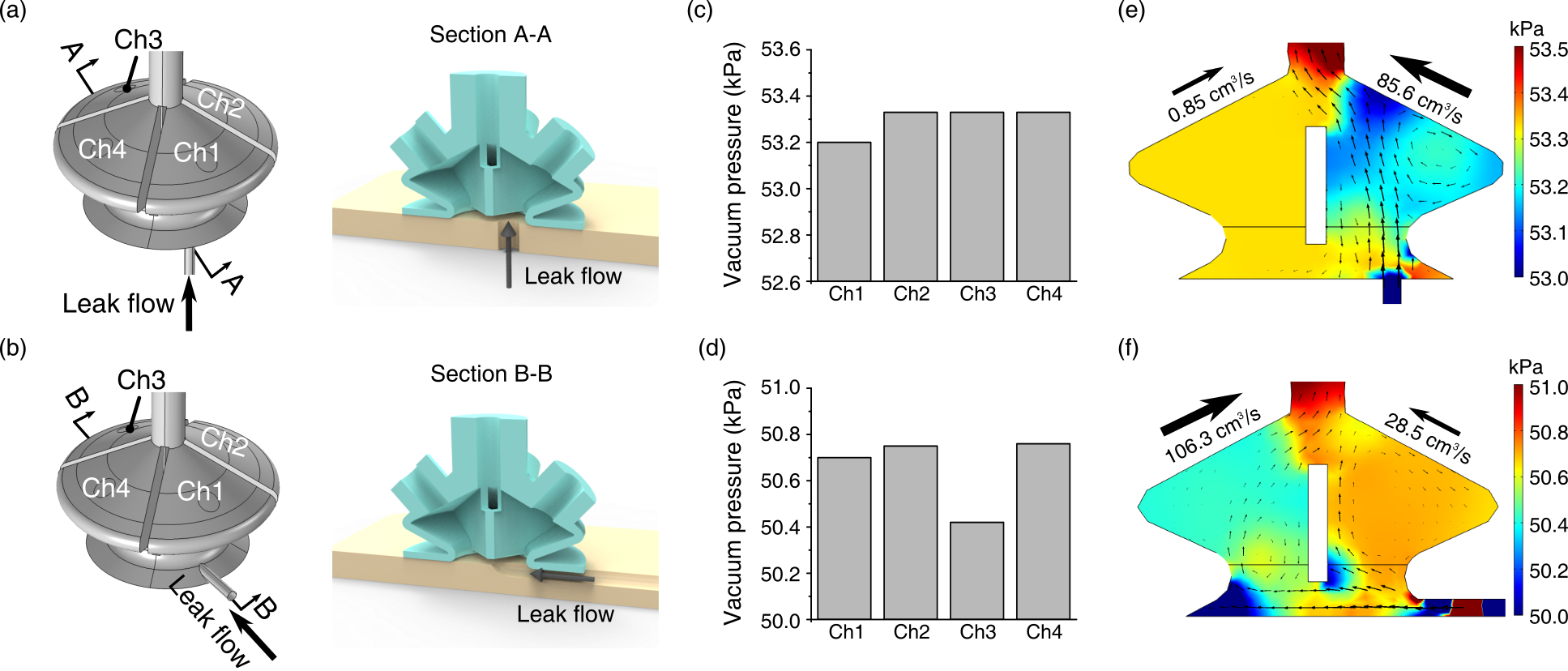
Using Computational Fluid Dynamics (CFD) simulation (COMSOL Multiphysics, turbulence model), we evaluate the gripper in two example suction flow cases: vertical and horizontal flow (Fig. 4a and b, respectively). The vertical flow case emulates when the suction cup only partially contacts a surface, or when the surface’s shape inhibits sealing. However, when the suction cup engages with a smooth flat surface, flow can only move inward from the outer edges of the cup, as in the horizontal flow case. This horizontal leak is common as the suction cup is wrenched from the surface after a suction seal is formed. Although the suction cup will deform under vacuum pressure, we use modeled rigid geometry in the CFD simulation. For each case, we approximate the leak flow direction with a small pipe (D = 1 mm, L = 7 mm) intersecting with one of the internal chamber volumes as shown in Fig. 4a-b. The boundary conditions of the vacuum pump pressures and flow rates match the experimental setup.
The simulation results suggest that the gripper can detect leakage flows using differences between the four pressure transducers. We defined vacuum pressure () as
| (1) |
where is atmospheric pressure. In the vertical leakage flow case, close to the leaking orifice shows the least vacuum pressure than the others (Fig. 4c). On the other hand, the horizontal leakage causes the diagonally opposite channel to have the lowest (Fig. 4d). These trends are supported by the flow results in Fig. 4e-f, where the vertical and horizontal orifices produce the highest flow rate in opposite chambers. The simulation result also shows an estimate of the pressure difference between chambers (0.4kPa) which must be differentiated by the selected pressure sensors.
III-C System integration
Four ported pressure sensors (Adafruit, MPRLS Breakout, 24 bit ADC, 0.01 Pa/count with an RMS noise of 5.0 Pa) connect with the four chambers of the smart suction cup via polyurethane tubes. The suction cup and the pressure sensors attach to a 3D printed fixture (Fig. 1a) and this fixture is attached to the wrist F/T sensor (ATI, Axia80, sampling rate 150 Hz) on the robot arm (Universal Robots, UR-10) as in Fig. 5. A microcontroller (Cypress, PSoC 4000s) is fixed to the arm proximal to the load cell and communicates with the four pressure sensors via I2C at a 166.7 Hz sampling rate.
A vacuum generator (VacMotion, VM5-NA) converts compressed building air to a vacuum source with a maximum vacuum of 85 kPa. A solenoid valve (SMC pneumatics, VQ110, On/off time = 3.5 / 2 ms), commanded by a microcontroller, regulates the compressed air as a means of moderating vacuum intensity. The vacuum hose that applies suction to the cup is attached at both the suction cup vacuum connector and proximal to the load cell to reduce tube movement and subsequent F/T coupling.
The experiments are conducted on a desktop computer running Ubuntu 20.04 with a 3.00-GHz Intel Core i5-7400 quad-core CPU and an Intel HD Graphics 630 GPU. The UR-10 controller is responsible for moving the robot to the target pose, while communication between the desktop computer and the UR-10 robot uses Real-Time Data Exchange (RTDE) over a standard TCP/IP connection. We used ROS (Noetic) to collect both pressure sensor and wrist force/torque (F/T) sensor data during experiments. An RBG-D camera (Intel, RealSense D435) is additionally mounted to the robot arm wrist such that it does not apply any wrenches on the F/T sensor. It takes photos (640x480 RGB resolution, 0.1 mm depth resolution), which are used in the bin-picking experiments.
IV Autonomous Haptic Search
The control goal is to enable the robot arm to make small end-effector pose adjustments in the direction that will eventually seal the suction cup, in other words bring the vacuum pressure of all channels closer to the maximum vacuum–85kPa for the fully sealed condition. We decompose autonomous haptic search motions into three direction unit vectors defined in the tool basis, shown in Figure 6: (1) lateral positioning or translation along in the - plane, (2) rotational alignment or rotation about in the - plane, and (3) axial movement or movement along . The lateral positioning assumes partial contact of the suction cup with an object or the presence of small holes underneath the cup. The rotational alignment assumes a misalignment between the suction cup and the surface normal of the object contact point. In both situations, we assume there is significant misalignment or the existence of bottom holes, resulting in vertical leak flows as depicted in Fig. 4(a). The axial movement ensures a consistent normal force, or -force, that is necessary to engage the suction with an object and maintain contact.
Both lateral positioning and rotational alignment search for a better grasping pose using smart suction cup pressure signals. To do so, pressures are first calculated for each cardinal direction by taking the average of the two chambers that correspond to that direction:111This first step aligns the cardinal points with the wall interfaces of the cup. Alternatively, one can directly assign chambers to cardinal directions, e.g., ; this would result in a tool basis rotation of about the direction compared to our implementation.
| (2a) | |||
| (2b) | |||
| (2c) | |||
| (2d) | |||
Pressure differentials across cardinal directions are then calculated as:
| (3a) | |||
| (3b) | |||
Using these values, the vectors and are calculated at each time step, in real time at a control rate of 125Hz.
IV-A Pressure Signal to Lateral Positioning
The lateral direction vector, , is defined to move the suction cup towards the channels with less leakage flow, i.e., higher vacuum pressure, as follows:
| (4a) | |||
| (4b) |
Then the lateral repositioning increments, and , are defined as follows:
| (5a) | |||
| (5b) | |||
where 0.5 mm, is the overall lateral positioning step size per control loop.
IV-B Pressure Signal to Rotational Alignment
The rotational direction vector (axis of rotation), , is defined to close the gap between the object and channels with high leakage flow, i.e., low vacuum pressure, as follows:
| (6a) | |||
| (6b) | |||
Given an overall rotational alignment step size of = 0.5, the rotation matrix R is calculated as follows:
| (7) |
where is the skew-symmetric operator,
| (8) |
Rotations are applied about the axis of rotation, along , which is always in the - plane and always intersects point .
IV-C Force Signal to Axial Motion
The axial step size , is calculated as follows,
| (9) |
where 0.1 mm is the axial step size per control loop.
IV-D Composition of Motion Primitives
To test different combinations of lateral and rotational motion in experiments, step sizes in the lateral and rotational directions are scaled as:
| (10a) | |||
| (10b) | |||
where and are new step sizes weighed by , which in turn change , , and , producing an overall transformation matrix, :
| (11) |
If , then = 0 and = 1, which results in pure lateral positioning. If , then = 1 and = 0, which results in pure rotational alignment. For any , axial force control remains unchanged to ensure contact with a surface.
V Experimental Methods
V-A Sensing Characterization for Haptic Search
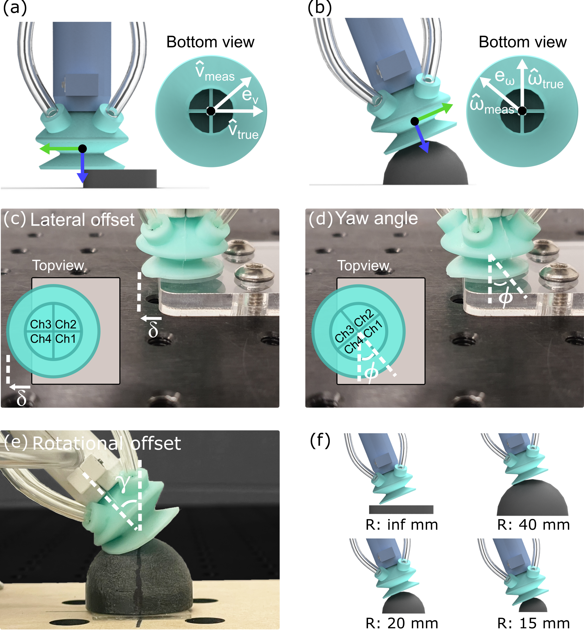
To characterize the Smart Suction Cup sensing performance relevant for (1) lateral positioning and (2) rotational alignment, we perform two characterization experiments, one for each. We swept lateral and rotational offsets from known reference points and analyzed the resulting pressure signals. From these pressure signals in each experiment, we compute measured and , respectively. Based on the physical experimental setups, we know the ground truth and that would move the suction cup towards a successful suction grasp with the shortest displacement. As shown in Fig. 8a-b, we report direction error as the unsigned angle between the measured and true direction vectors:
| (12a) | |||
| (12b) | |||
for lateral positioning and rotational alignment, respectively, where , .
V-A1 Lateral Positioning characterization procedure
In the lateral haptic characterization experiments, we positioned and oriented the suction cup relative to the edge of a flat plate, as shown in Fig. 8c-d. We define the lateral offset as the exposed lip length, and the orientation is parameterized by the yaw angle to test for asymmetry in the pressure sensor response. A yaw angle of corresponds to . To maintain a constant vertical distance between the flat plate and suction cup across all trials, we apply a normal force of 1.5 N at a lateral offset of 0 mm and fix this height of the suction cup. We sweep the lateral offset from 0 to 23 mm with a 1 mm increment, noting that an offset of 11.5 mm is when the point is vertically aligned with the edge of the plate, and sweep the yaw angle from to with a increment. In each test pose, we average the sensor data over a measurement period of 2 seconds.
V-A2 Rotational Alignment characterization procedure
In rotational haptic characterization, the suction cup was placed on and oriented relative to a sphere, as in Fig. 8e, such that the point is vertically aligned with the highest point of the dome. We define the rotational offset as the angle between the true surface normal at this highest point (vertically upward) and . Domes with different diameters (15 mm, 20 mm, 40 mm, and flat plate) are selected, as in Fig. 8f, with the 15mm radius dome representing the smallest sphere that the suction cup can grasp in this study. In this experimental setup, . To initialize an experiment, we use force control to reach a target 1.50.1 N normal load444This type of force control to an exact value often leads to system vibrations. For the parameters used in our controller, with the tolerance of 0.1 N and control rate of 125 Hz, we did not observe substantial vibrations., with . We record the position of in space at this moment, and then pivot about it while regulating the force along . We sweep from 45∘ to 0∘ with 1∘ steps. At each offset, we average pressure measurements for 2 seconds of steady state readings.
V-B Bin-picking
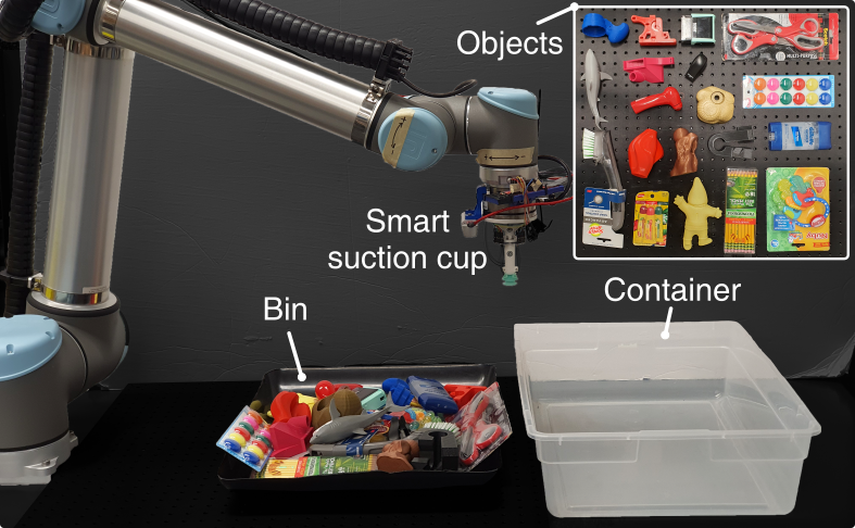
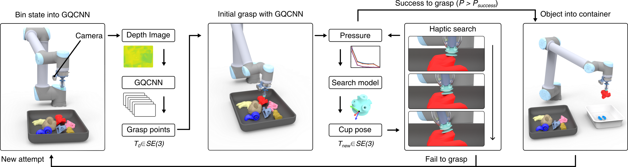
We set up a bin-picking task similar to that of [23] to evaluate the functional performance of the proposed haptic search algorithms. The robot system was programmed to pick objects up from a bin and transport them to a designated container, as shown in Fig. 8. For a given trial, the robot was first set with a particular controller. The system was then presented with 19 adversarial objects in a bin. Five of the objects were 3D-printed objects taken directly from the list of Adversarial objects from [5]. Eight of them were taken directly from the Level 3 object set in [23], which includes both 3D-printed and commercial objects. The rest of the objects were picked based on difficulty for a vision-based planner, specifically adversarial objects with imperceptible features like transparency, reflectivity, and small surface features.
Before the start of each trial, the operator placed the complete set of objects into the bin by first shaking them loosely in the container, inverting that container to drop them into the bin, and manually adjusting objects only to ensure that they were below the rim of the bin. The robot then continuously attempted to perform the pick-and-place task until an end-trial condition was met, and the number of successfully grasped objects was recorded. In each trial, 57 attempts (three times the number of objects) were performed, and the trial stopped when 10 consecutive grasp attempts failed or no feasible grasping points remained available. We conducted five bin-picking trials for each tested control method.
The process for each trial is shown in Footnote 3. On each grasp attempt within a given trial, a point cloud of the bin state with objects is inputted into the Grasp Quality Convolutional Neural Networks (GQCNN) [24] to generate 30 grasp point candidates with a grasp quality value ranging from 0 to 1 and corresponding suction cup pose. Among the candidates, the pose with the highest quality value and no previous failures is attempted.555We implement a simple memory system to avoid repeated failures at the same grasp point. When a grasp is unsuccessful, the grasp point is stored and any points within 3 cm of previous failure points are considered non-feasible. The system stores up to three previous failures and is reset when the suction cup successfully grasps an object. Note that we have not re-trained this algorithm for our particular robot system or object set. The robot approaches the selected grasp point with a 15 mm offset in the estimated surface normal direction. Then, it approaches the surface along the estimated normal until normal force reaches 1.5 N. The suction cup then initiates vacuum suction and checks the vacuum pressure of all channels to determine whether it has successfully grasped an object. We define a grasp success if the mean vacuum pressure is greater than 15 kPa, equivalent to holding 350 g with our suction cup. This estimate assumes the seal ring diameter is at the midpoint of the suction cup lip, or 17 mm across. The heaviest object lifted in experiments weighs less than 200 g, providing a safety margin of at least 150 g.
If a successful grasp is not detected after the initial grasp attempt with GQCNN, then the robot starts its specified search strategy to adjust the cup pose. During this search phase, a grasp is considered a failure if the suction cup moves away from the initial grasp point by more than 3 cm, rotates by more than 45 from the initial pose, or if the search time exceeds 15 seconds.666This maximum search time of 15 seconds was selected after preliminary experiments yielded diminishing grasp success after this time frame. In applications where speed is important, it would be impractical to search for an un-ending amount of time without a successful grasp. If the robot fails to grasp an object, it returns to the initial position and starts a new attempt. However, if at any point during the search procedure a successful grasp is detected, the robot then attempts to lift and move the object. Grasp failure is recorded if the object is dropped prior to the intentional release of the object into the container.
We evaluate eight total experiments: six with different haptic searching methods and two experimental controls. We implement five haptic search strategies by modifying the value of from 0 to 1 in increments of 0.25. Specifically, we denote the values of , , , , and as an of 0, 0.25, 0.5, 0.75, and 1, respectively. Also, we include a haptic search strategy which alternates a weight value between and every 0.5 s, denoted as in order to test the decoupling of motion between lateral positioning and rotational alignment. The first control condition is the application of GQCNN without any additional search method applied. As another experimental control case, we conduct a random search with Brownian motion (BM), or Weiner process, in the lateral direction; the lateral scalar step sizes in Eq. 11 , and , are chosen to make the standard deviation of the distance to be 3 cm from the initial grasp point after 15s of searching time.
VI Results
VI-A Lateral Positioning sensor characterization
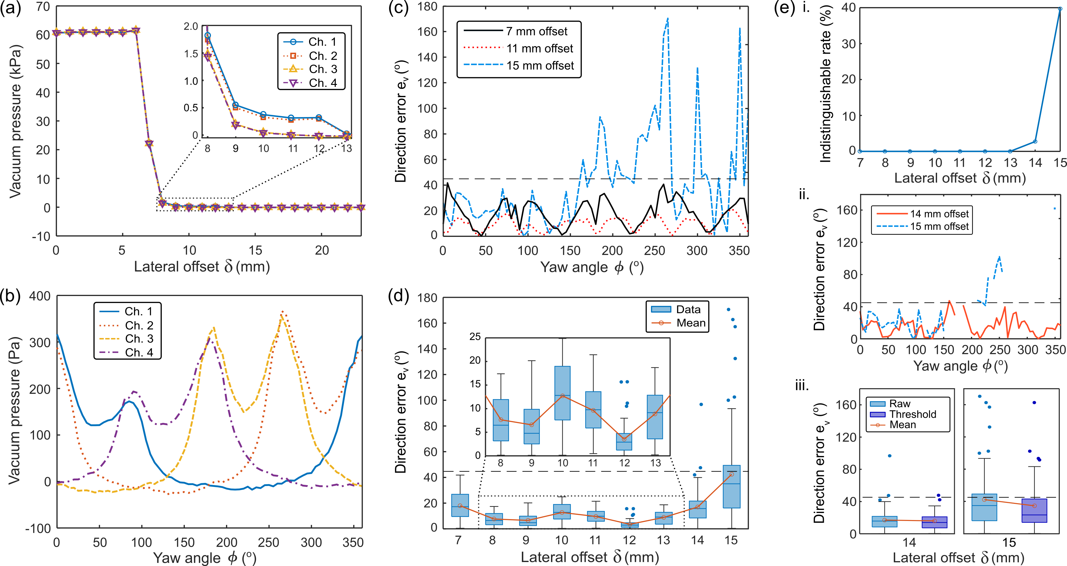
The characterization results of lateral positioning are presented in Fig. 10. In Fig. 10a, the vacuum pressures from all channels are shown as lateral offset changes while yaw angle is held constant at . All four channels remain over 60 kPa until the lateral offset reaches 6 mm; at these offsets, less than 7 mm, the suction cup seals completely with the plate and no haptic search is needed to grasp successfully. Note that the entire lip of this cup design does not necessarily need to be in full contact to generate a seal. Vacuum pressures decrease starting from a 7 mm lateral offset. The figure inset shows the region of offsets in which notable pressure differences exist between different chambers. Between 16 mm and 23 mm lateral offset, pressure readings remain at 0 kPa across all chambers. It is therefore expected that directional signals will be most informative between 7 and 15 mm of offset.
To demonstrate how the pressure readings vary with the yaw angle, we vary from 0 to 360 with the edge of the plate located at the center of the suction cup (11.5 mm offset); we average the pressure readings at 11 mm and 12 mm lateral offset to estimate this cup alignment. As shown in Fig. 10b, the vacuum pressures in each chamber vary periodically with the change in yaw angle. At 0 yaw angle, chambers 1 and 2 overlap with the plate, showing higher vacuum pressure than the pressures from chambers 3 and 4. At every 90 of yaw angle, two chambers seal on the plate’s surface, causing vacuum pressures to show peaks of two chambers. Given the chamber geometry of the cup, there will be higher overall vacuum pressure applied to the cup when more of the 4 chambers become sealed. This explains why we see two peaks per chamber, rather than just one, as the two adjacent chambers simultaneously break seal between local maxima. Variability between chambers is also seen, for example the maxima at is smaller than the others. Small variation could be caused by fabrication and assembly, as well as compliance in the suction cup, leading to asymmetric buckling deflections of the internal chamber dividers upon contact, as observed in prior work [1]. Regardless of chamber-to-chamber interaction and nonidealities, at each tested yaw orientation the 4 chambers provide a unique combination of readings to support the estimation of the state.
In order to understand the interpretation of these signals in our control algorithm, across both and , we visualize direction errors with pressure sensor readings using Eq. 12a in Fig. 10c-d. Direction errors from lateral offsets between 7 mm and 15 mm with 4 mm increments are shown in Fig. 10c. The boundary indicates the directions that would enable faster haptic search for a better grasping point, by moving the cup towards the plate at a rate faster than along the edge of the plate. At 7 mm and 11 mm lateral offset, the direction errors show that all data is below the boundary line. At a 15 mm lateral offset, some errors go above the boundary. The result shows that direction errors have a cyclic pattern every 45, reflecting the internal wall structure of the suction cup with four chambers.
In Fig. 8d, we report the direction error for all trials between 7 and 15 mm offset. Each lateral offset has 73 data points, where we sweep yaw angles from 0 to 360 with a 5 increment. The result shows box plots with the means of the data. No data exceeds the boundary from 7 mm to 13 mm lateral offset. However, within this range, error is greatest at 7 mm. It makes sense that direction error increases as the offset approaches 6 mm, as the suction cup becomes fully sealed and flow stops altogether. For the 7 mm case, as demonstrated in Fig. 4d-f, flow can become predominantly horizontal at the transition to the fully-sealed state, thereby decreasing the pressure difference between the exposed and covered chambers. At both 14 and 15 mm lateral offset, where pressure differences become small, several data points show error over , yet the mean of the direction error remains below this threshold.
At large offsets, greater than 15 mm, the pressure approaches 0 Pa and increases further, meaning that all four channels are open and not forming effective differential pressures. We therefore apply a threshold condition of 10 Pa during controller implementation such that, when all chambers are below this level, the direction estimate is set to (no motion). The rate at which this condition is met, which we call the indistinguishable rate, at different lateral offsets is shown in Fig. 10e i. The indistinguishable rates from thresholding are found to be 2.7% and 39.73% at 14 mm and 15 mm lateral offset, respectively, while no data are indistinguishable between 7 mm and 13 mm lateral offset. Fig. 10e ii shows the corresponding result of direction errors at 14 mm and 15 mm lateral offset, where the indistinguishable data points are eliminated. Fig. 10e iii shows the change in resulting from the threshold condition. Before thresholding, the mean of direction error at 14 mm lateral offset is 16.99, which decreases to 15.70 after thresholding. At a 15 mm lateral offset, the mean direction error changes from 42.42 to 34.71. In practice, motion will only occur when at least one channel measures a degree of flow restriction – if there is no measurable suction contact the cup will remain stationary.
VI-B Rotational Alignment sensor characterization
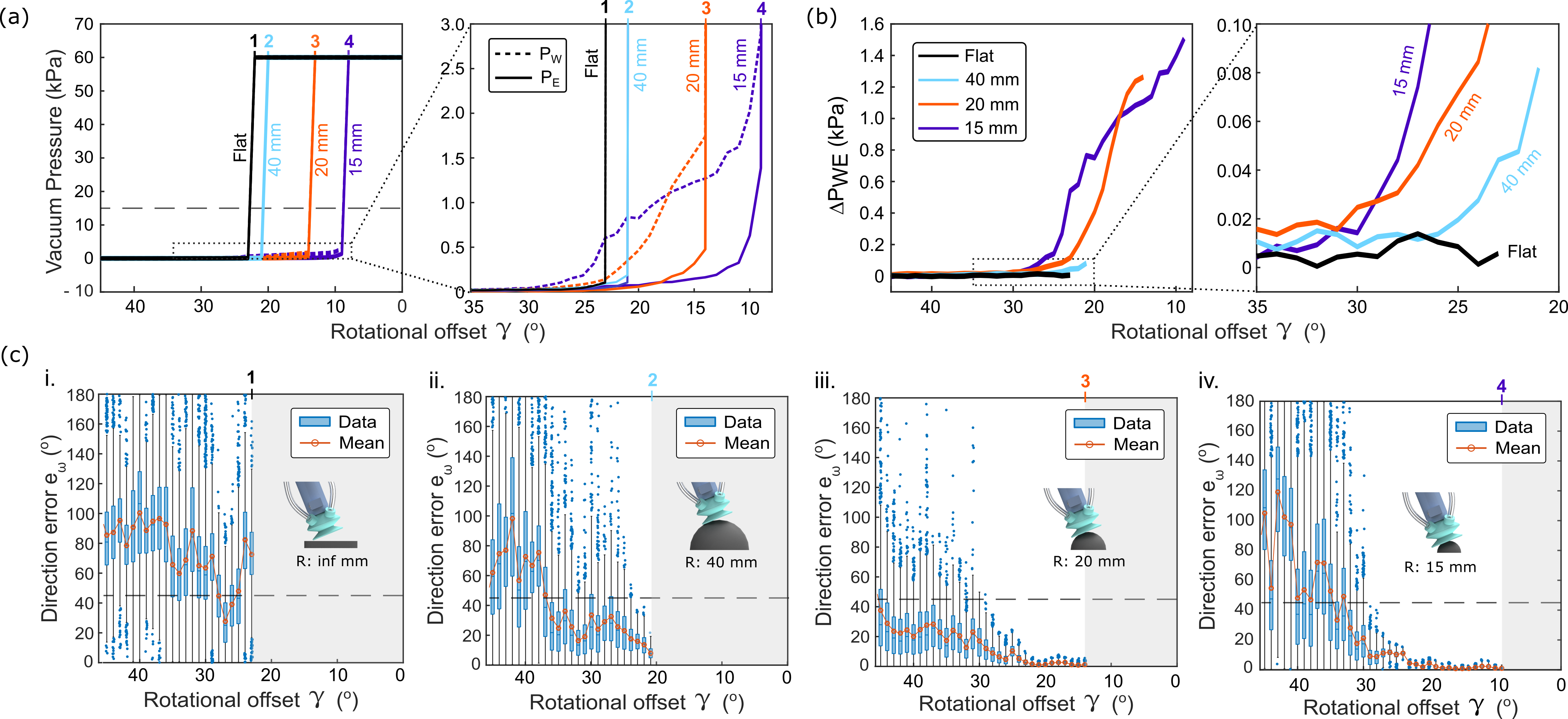
The characterization results of rotational alignment are presented in Fig. 11. Since the suction starts without a seal, we read the plot with decreasing rotational offset from left to right. The cup initially starts at and all channels read close to 0 kPa. The critical rotational offset, where the vacuum seal is formed, is seen by a rapid increase in the vacuum pressure (Fig. 11a). This critical offset angle becomes smaller as the radius of the dome decreases, indicating that smaller radius domes require more precise alignment with the surface normal to successfully grasp. At rotational offsets smaller than the critical offset angle, the vacuum pressures are consistently near 60 kPa across all channels. The control condition for successful grasping, , is shown as the horizontal dashed line. The region of interest for haptic search occurs when there is the presence of pressure differentials within the cup, detailed in the figure, comparing and . The difference is directly plotted as in Fig. 11b after removing data points where . For the 15 and 20 mm radius domes, signals rise as high as 1.5 and 1.2 kPa, respectively, over larger rotational offset ranges than the 40 mm dome or flat plate. The pressure differential for the flat plate in particular never even reaches a of 20 Pa, because the compliant lip rapidly deforms and pulls itself into the surface before substantial differential flows can occur inside the cup due to chamber occlusion. We therefore expect tactile sensing to provide more useful prediction of on higher curvature objects, where smaller domes can better occlude chambers before the critical angle is reached and more careful alignment with surface normal is required.
As shown in Fig. 11c, the test results indicate that the direction error (, Eqn. 12b) is lower for objects with smaller radii. Each subplot i-iv represents a trial on a different object and data for which is omitted. When we add a dashed boundary line of , similar to in lateral search characterization, we see that errors consistently drop below at rotational offsets of 30, 31, 23 for domes with radii of 15 mm, 20 mm, and 40 mm, respectively. On the other hand, the flat plate error does not fall below this threshold consistently on the flat plate because remains small up to the critical angle. The smaller radii objects (R=15 mm and 20 mm) show the most accurate predictions () close to the critical rotational offset. This result suggests that the proposed haptic search method can successfully grasp objects with small critical offset angles (e.g., 8 in R=15 mm object), even with high visual perception error of surface normal up to 30.
VI-C Bin-picking
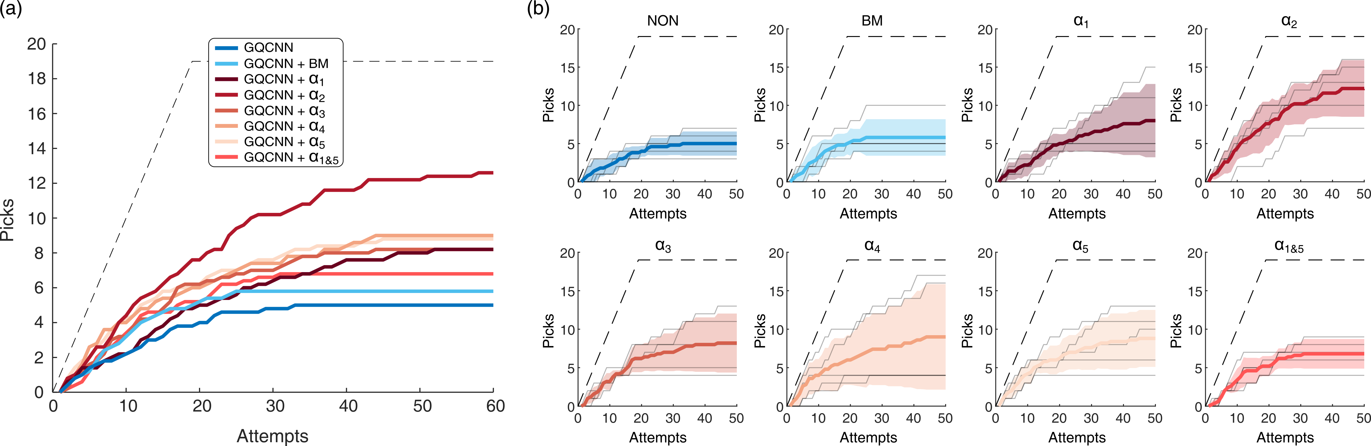
We evaluate the bin-picking test conditions defined in Section V-B, with results shown in Fig. 12. The picks-per-attempts mean average from across five independent trials for each condition is reported in Fig. 12a; the six haptic search conditions are in shades of red while the the two experimental control cases are in shades of blue. All trials are reported for each test condition experiment in Fig. 12b. The dashed lines on all plots indicate the ideal case where every grasp attempt is successful without any failures.
The control case “GQCNN” or “NON,” which has no search phase, shows an average of 5 1.58 successful picks. This means the robot system was able to successfully pick-and-place these objects from the bins without any haptic search assistance. The control case “GQCNN + BM,” which includes random Brownian motions in lateral direction during the search phase, results in an average of 5.8 2.39 successful picks. This shows that the introduction of non-haptically-driven motion after the initial grasp attempt can provide minor improvements. Comparing the two control cases with this ideal performance, we see the difficultly of the selected adversarial pick-and-place task. Of the two control cases, we propose that it is more appropriate to compare haptically-driven results with the “GQCNN + BM” control case because it represents baseline benefits from the presence of a search phase.
The proposed haptic search methods are labeled to and . Results show that provides the highest number of successful picks per trial, with an average of 12.6 4.16. Lateral positioning () and rotational alignment () show reduced results similar to one another, with 8.2 5.17 and 8.8 3.70 successful picks, respectively. results in an average of 8.2 3.83 successful picks and provides successful picks (9 6.86), but with the largest standard deviation. For the performance of the alternating haptic search method , it shows the lowest successful picks of 6.8 1.92 among all the haptic search methods evaluated. Overall, these results demonstrate the effectiveness but also the between-trial variability of the proposed haptic search methods. Out of these methods, , which predominantly performs lateral search but with some rotational alignment, best improves the success rate of bin picking by the robot system. However, between trial variability indicates that the potential benefits of haptic search is sensitive to initial bin state.
We can then compare the autonomous haptic search methods with the experimental control cases. In the region between 0 and 5 pick attempts, there is little difference between all eight methods. This indicates that success is driven by the GQCNN method, mostly because we attempt the grasping pose with the highest quality value first. The methods diverge in performance after 5 attempts, where the GQCNN and methods show lower performance than the other six methods. At 25 or more bin pick attempts, all six haptically-driven methods outperform the two experimental control methods. This indicates that autonomous haptic search methods are helpful to expand achievable grasp points, to now include those that GQCNN alone is unable to accurately predict.
Here, we quantify how much fine-tuning is executed through haptic search on average. Among the successful haptic search trials, across all six haptically-driven methods, the mean cartesian displacement from the initial pose was 4.8 mm with a maximum of 13.9 mm. Mean path length was 8.7 mm with a maximum of 32.7 mm. Mean angular displacement was 5.9∘ with a maximum of 25.2∘. Mean angular distance traveled was 6.8∘ with a maximum of 39.1∘.
VII Discussion
VII-A Sensor characteristics
Through varying the lateral displacement and yaw of the cup against a flat plate edge and varying orientation with domes of different sizes, we characterized the scale and types of pressure signals that the Smart Suction Cup produces. We also demonstrated how these raw signals are interpreted using our proposed haptic search procedure. However, plates and domes represent primitive shapes. The complexity of object geometries in real-world scenarios, with a combination of vertical and horizontal flows, will likely impact the haptic search effectiveness of the suction cup, making it challenging to identify suitable direction vectors. This may help us to understand why, at times, we observed certain unproductive haptic behaviors emerge during the bin-picking task.
We found in sensor characterization tests that thresholding reduced direction error, by eliminating cases where pressure differential measurements are too low to produce reliable estimates when sensor noise starts to dominate. At the same time, it is unlikely that perfect prediction accuracy is essential in effectively deploying Smart Suction Cup haptic search. Specifically, the prediction accuracy appears to improve as the cup gets closer to a successful grasp. During haptic search, if, as a result of noisy signals due to low pressures, the cup randomly reaches any state where a more accurate prediction can be better made, then the behavior will converge on a successful grasp over time. We posit that this will be especially true if, on average, predictions start from a place that are within 90∘ of the true direction vector. In future work, conducting closed-loop control experiments, rather than stationary sensor characterization, would identify the highest possible offsets for which haptic search still yields a successful grasp, including on a wider variety of object shapes.
In the lateral search case and especially the rotational alignment case, we find that the compliant material and the bellows of the suction cup allows it to engage with objects even with postural errors to some extent. However, for objects with high curvature and critical features such as holes, the inherent tolerance of the suction cup may not be sufficient. In such cases, our proposed haptic search method is expected to enhance the operational tolerance even when the vision system fails to capture those features accurately.
VII-B Bin-picking observations
Bin-picking experiments suggest that a physical search phase after contact is made can improve grasp success, especially when employing autonomous haptic search methods that respond to measured contact conditions. The fact that all haptic search methods tested provided some increase in picking success rate as compared with experimental controls, including with random searching, shows how responding to contact pressures, even with a simple model-based controller, holds potential thus motivating ongoing investment in the Smart Suction Cup capability. We used a single suction cup prototype throughout all of these bin-picking-experiments, representing at least 1316 autonomous grasp attempts, without incurring damage to the cup or needing replacement. The Smart Suction Cup design, where the cup is fabricated in a single-step casting process and electronics are remote from the cup, thus appears to provides reliable and physically robust performance.
We saw the biggest performance increase with the haptic search method, whose motion is a mix of lateral positioning with a bit of rotational alignment. Though it matches our expectations that a coupled motion would yield better results than purely sliding () or rotating (), because most objects have both edges and curves, it is less obvious why outperforms and . A possible theory is that the rotational alignment search counteracts the lateral search, so finding the optimal tuning between them is required. When the suction cup has partial contact, the lateral search attempts to reinforce contact on the contacted side by moving towards it, while the rotational alignment loosens the contact side and attempts to make balanced contact over all channels. Therefore, an appropriate balance between the two modes should be adjusted. We believe that provides the best balance among the five presets in general, but each geometry may require a different optimal balance between the two modes. We leave this local, object-specific controller optimization as a future work.
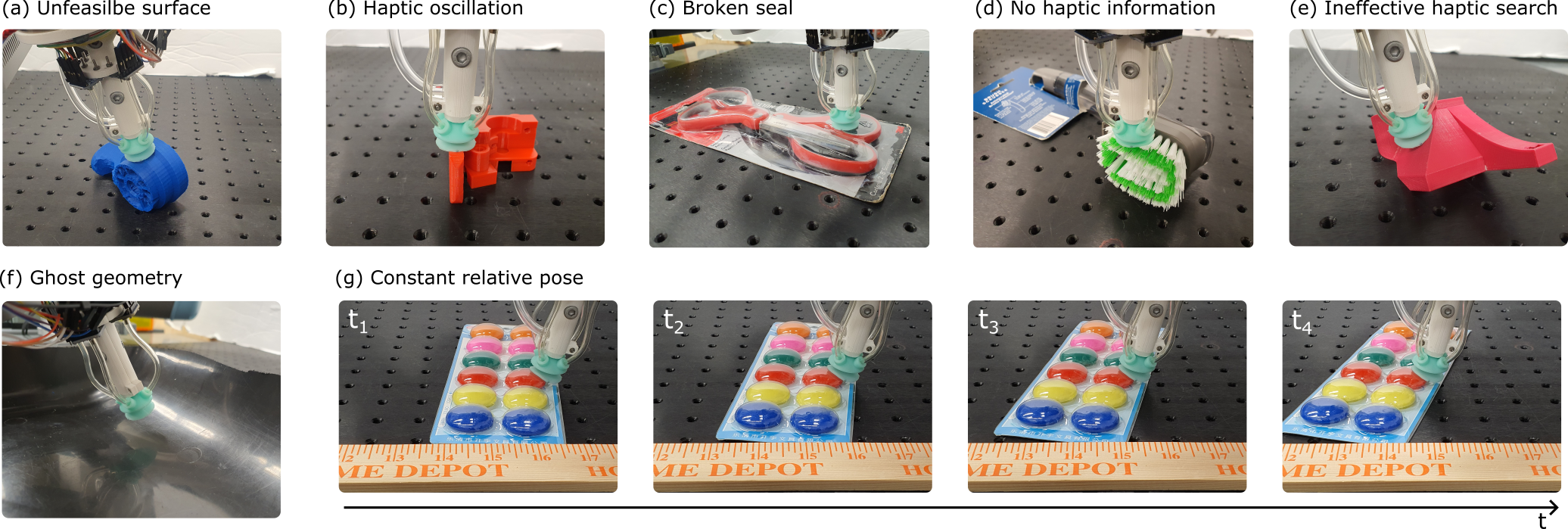
During the bin-picking trials with autonomous haptic search, we observed different common grasp failure modes. We classify them into seven categories, as shown in Fig. 13:
-
(a)
Unfeasible surface: Haptic search starts at an infeasible surface, where possible grasp poses are beyond the searching boundary.
-
(b)
Haptic oscillation: Haptic search oscillates in a region where haptic information makes the cup move back and forth without converging to a graspable point.
-
(c)
Broken seal: The contact wrench applied to the cup is too large to lift an object. This typically occurs when the suction cup tries to grasp a heavy object from the edges, also reported in [25].
-
(d)
No haptic information: The suction cup cannot get any distinguishable haptic data from a surface, such as the bristles of the brush (P10 Pa).
-
(e)
Ineffective haptic search: A surface is feasible and haptically searchable, but the system uses an ineffective behavior. The example shows a case where the suction cup is using lateral positioning but would benefit more from rotational alignment.
-
(f)
Ghost geometry: Reflective and/or transparent materials yield artifacts, resulting in ghost geometries in a depth image. The example in the figure shows the suction cup is trying to grasp in the air because the light from the ceiling is reflected on the bin surface.
-
(g)
Constant relative pose: During haptic search, a loose object can be pushed such that the relative position between the cup and object remains unchanged despite robot motion. Given the new position of the object, the next attempt may consider the same grasp point as a valid candidate as its pose in the world frame changed.
Several of these error types occur because the vision-based grasp planner initializes the grasp at a point in which a suction grasp is locally impossible. The cases in Fig. 13 (a), (c), and (f) are not recoverable using contact condition condition sensing. To combat these, the camera and/or visual planner performance would need to be improved. However, for cases in Fig. 13 (b), (d), (e), and (g), new adaptive haptic search controllers designed to identify and overcome such failure cases could further improve grasping in future work. For instance, the failure mode (g) may be effectively addressed through a jumping haptic search approach. In this approach, the suction cup retracts from an object and then re-approaches with an adjusted pose. This prevents the suction cup from exerting continuous pressure on an object while making pose adjustments. We recommend also coupling vision with the haptic search process. For example, camera information could be used to select appropriate haptic search methods in response to case (e). Or vision could identify object movement in (g) to adapt behavior on the fly; for example, in [1], we propose that one could dynamically reduce the suction pressure of the vacuum in order to achieve more gentle sliding over objects.
In the present work, we made the deliberate choice not to re-train the GQCNN algorithm for our particular robot system, resulting in overall low planner performance. In our case, we use a different camera, robot arm, object set, room/lighting, gripper, and bin from the ones used in training. The purpose of this choice is to generate a scenario that emulates a quick-adopt case for such technology, since generalizability is an ongoing challenge for such planning algorithms [26]. The present work therefore shows that the use of a Smart Suction Cup can be one tool in ameliorating errors that arise specifically in previously unseen systems. Future work will investigate how planner optimization and hardware selection (e.g., higher spatial resolution camera) affects the role of autonomous haptic search.
VII-C Printed Circuit Board demonstration
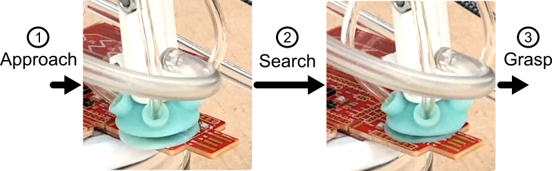
In the bin-picking experiment, the tested objects all had at least one smooth graspable surface for the suction cup to grip. However, some real-world objects have bumpy surfaces without any obvious continuously-smooth regions. For example, a Printed Circuit Board (PCB) with Integrated Circuits (IC) soldered on it and via holes might prevent the use of a suction cup, if the cup would fail to grasp at most surface locations. However, haptic search behaviors can still enable the grasping of such surfaces, adapting around local features to achieve a seal. To demonstrate this behavior, we fix a printed PCB to the table and allow the cup to search for a grasp point using only lateral positioning, or . Fig. 14 shows how the cup is able to find a successful grasp point over one of the IC’s. Future work will measure to what extent the cup can respond productively on surfaces with different types of porosity and rugosity profiles for real-world applications.
In Fig. 10, the directional errors in lateral search on a flat, smooth plate commonly reach almost 20∘ for the best case lateral offsets between 8 and 13 mm. These errors may appear unsatisfying and at times result in longer searching paths than desired. This directional error provides one reasonable explanation for the edge-following behavior that emerges at Grasp point 3 in Supplementary Video. However, the PCB demonstrations show how this error does not necessarily result in overall failure during smart suction haptic search; the controller continues to adjust its directional estimate every 0.5 mm as it moves, ultimately leading to a successful grasp. Regardless, future work should investigate how performance – such as time and distance to successful grasp – may be optimized through cup and algorithm design.
VIII Conclusion
The four-chamber cup design of the Smart Suction Cup, with remote pressure transducers, provides a reliable solution for generating differential airflows and protecting sensitive electronics from physical damage. In this work, our proposed autonomous haptic search method – a model-based approach for estimating lateral positioning and rotational alignment – enables the suction cup to adjust to a successful pose for suction grasping, effectively increasing tolerance to positioning or misalignment error induced by errors from a vision-based grasp planner. The Smart Suction Cup holds the potential to improve gripping in various scenarios that already deploy vacuum grippers, such as recycling facilities, warehouses, manufacturing, and logistics robots.
VIII-A Future work
This study presented a single implementation of the Smart Suction Cup and one particular model-based approach to generating haptic searching behaviors in response to pressure readings. In future work, we seek to explore new soft cup designs to both improve gripping performance while studying how parameters, like the number of chambers, affect sensing. Next steps include optimization and learning-based approaches for sensor characterization and mixing lateral positioning and rotational alignment. These adaptive methods may be informed by visual and haptic information, for example. Finally, the ultimate goals of this line of work is to explore the adoptability and lifetime of such technology in real-world application.
IX Acknowledgments
This work is supported by InnoHK of the Government of the Hong Kong Special Administrative Region via the Hong Kong Centre for Logistics Robotics and by the University of California at Berkeley. The authors thank the members of the Embodied Dexterity Group.
References
- [1] T. M. Huh, K. Sanders, M. Danielczuk, M. Li, Y. Chen, K. Goldberg, and H. S. Stuart, “A multi-chamber smart suction cup for adaptive gripping and haptic exploration,” in 2021 IEEE/RSJ International Conference on Intelligent Robots and Systems (IROS). IEEE, 2021, pp. 1786–1793.
- [2] D. Morrison, A. W. Tow, M. Mctaggart, R. Smith, N. Kelly-Boxall, S. Wade-Mccue, J. Erskine, R. Grinover, A. Gurman, T. Hunn, et al., “Cartman: The low-cost cartesian manipulator that won the amazon robotics challenge,” in 2018 IEEE International Conference on Robotics and Automation (ICRA). IEEE, 2018, pp. 7757–7764.
- [3] A. Zeng, S. Song, K.-T. Yu, E. Donlon, F. R. Hogan, M. Bauza, D. Ma, O. Taylor, M. Liu, E. Romo, et al., “Robotic pick-and-place of novel objects in clutter with multi-affordance grasping and cross-domain image matching,” The International Journal of Robotics Research, vol. 41, no. 7, pp. 690–705, 2022.
- [4] W. Wan, K. Harada, and F. Kanehiro, “Planning grasps with suction cups and parallel grippers using superimposed segmentation of object meshes,” IEEE Transactions on Robotics, vol. 37, no. 1, pp. 166–184, 2020.
- [5] J. Mahler, M. Matl, X. Liu, A. Li, D. Gealy, and K. Goldberg, “Dex-net 3.0: Computing robust vacuum suction grasp targets in point clouds using a new analytic model and deep learning,” in 2018 IEEE International Conference on robotics and automation (ICRA). IEEE, 2018, pp. 5620–5627.
- [6] H. Cao, H.-S. Fang, W. Liu, and C. Lu, “Suctionnet-1billion: A large-scale benchmark for suction grasping,” IEEE Robotics and Automation Letters, vol. 6, no. 4, pp. 8718–8725, 2021.
- [7] Q. Shao, J. Hu, W. Wang, Y. Fang, W. Liu, J. Qi, and J. Ma, “Suction grasp region prediction using self-supervised learning for object picking in dense clutter,” in 2019 IEEE 5th International Conference on Mechatronics System and Robots (ICMSR). IEEE, 2019, pp. 7–12.
- [8] H.-G. Cao, W. Zeng, and I.-C. Wu, “Reinforcement learning for picking cluttered general objects with dense object descriptors,” in 2022 International Conference on Robotics and Automation (ICRA). IEEE, 2022, pp. 6358–6364.
- [9] S. Aoyagi, M. Suzuki, T. Morita, T. Takahashi, and H. Takise, “Bellows suction cup equipped with force sensing ability by direct coating thin-film resistor for vacuum type robotic hand,” IEEE/ASME Transactions on Mechatronics, vol. 25, no. 5, pp. 2501–2512, 2020.
- [10] H. J. Lee, S. Baik, G. W. Hwang, J. H. Song, D. W. Kim, B.-y. Park, H. Min, J. K. Kim, J.-s. Koh, T.-H. Yang, et al., “An electronically perceptive bioinspired soft wet-adhesion actuator with carbon nanotube-based strain sensors,” ACS nano, vol. 15, no. 9, pp. 14 137–14 148, 2021.
- [11] E. Shahabi, F. Visentin, A. Mondini, and B. Mazzolai, “Octopus-inspired suction cups with embedded strain sensors for object recognition,” Advanced Intelligent Systems, vol. 5, no. 2, p. 2200201, 2023.
- [12] S. Doi, H. Koga, T. Seki, and Y. Okuno, “Novel proximity sensor for realizing tactile sense in suction cups,” in 2020 IEEE International Conference on Robotics and Automation (ICRA). IEEE, 2020, pp. 638–643.
- [13] S. Sareh, K. Althoefer, M. Li, Y. Noh, F. Tramacere, P. Sareh, B. Mazzolai, and M. Kovac, “Anchoring like octopus: biologically inspired soft artificial sucker,” Journal of the royal society interface, vol. 14, no. 135, p. 20170395, 2017.
- [14] S. T. Frey, A. T. Haque, R. Tutika, E. V. Krotz, C. Lee, C. B. Haverkamp, E. J. Markvicka, and M. D. Bartlett, “Octopus-inspired adhesive skins for intelligent and rapidly switchable underwater adhesion,” Science Advances, vol. 8, no. 28, p. eabq1905, 2022.
- [15] V. Müller, T.-L. Lam, and N. Elkmann, “Sensor design and model-based tactile feature recognition,” in 2017 IEEE SENSORS. IEEE, 2017, pp. 1–3.
- [16] C. Eppner, S. Höfer, R. Jonschkowski, R. Martín-Martín, A. Sieverling, V. Wall, and O. Brock, “Lessons from the amazon picking challenge: Four aspects of building robotic systems.” pp. 4831–4835, 2016.
- [17] J. M. Romano, K. Hsiao, G. Niemeyer, S. Chitta, and K. J. Kuchenbecker, “Human-inspired robotic grasp control with tactile sensing,” IEEE Transactions on Robotics, vol. 27, no. 6, pp. 1067–1079, 2011.
- [18] K. Hang, M. Li, J. A. Stork, Y. Bekiroglu, F. T. Pokorny, A. Billard, and D. Kragic, “Hierarchical fingertip space: A unified framework for grasp planning and in-hand grasp adaptation,” IEEE Transactions on robotics, vol. 32, no. 4, pp. 960–972, 2016.
- [19] Y. Chebotar, K. Hausman, Z. Su, G. S. Sukhatme, and S. Schaal, “Self-supervised regrasping using spatio-temporal tactile features and reinforcement learning,” in 2016 IEEE/RSJ International Conference on Intelligent Robots and Systems (IROS). IEEE, 2016, pp. 1960–1966.
- [20] B. Wu, I. Akinola, J. Varley, and P. Allen, “Mat: Multi-fingered adaptive tactile grasping via deep reinforcement learning,” arXiv preprint arXiv:1909.04787, 2019.
- [21] F. R. Hogan, M. Bauza, O. Canal, E. Donlon, and A. Rodriguez, “Tactile regrasp: Grasp adjustments via simulated tactile transformations,” in 2018 IEEE/RSJ International Conference on Intelligent Robots and Systems (IROS). IEEE, 2018, pp. 2963–2970.
- [22] R. Calandra, A. Owens, D. Jayaraman, J. Lin, W. Yuan, J. Malik, E. H. Adelson, and S. Levine, “More than a feeling: Learning to grasp and regrasp using vision and touch,” IEEE Robotics and Automation Letters, vol. 3, no. 4, pp. 3300–3307, 2018.
- [23] J. Mahler, M. Matl, V. Satish, M. Danielczuk, B. DeRose, S. McKinley, and K. Goldberg, “Learning ambidextrous robot grasping policies,” Science Robotics, vol. 4, no. 26, p. eaau4984, 2019.
- [24] V. Satish, J. Mahler, and K. Goldberg, “On-policy dataset synthesis for learning robot grasping policies using fully convolutional deep networks,” IEEE Robotics and Automation Letters, 2019.
- [25] K. Sanders, M. Danielczuk, J. Mahler, A. Tanwani, and K. Goldberg, “Non-markov policies to reduce sequential failures in robot bin picking,” in 2020 IEEE 16th International Conference on Automation Science and Engineering (CASE). IEEE, 2020, pp. 1141–1148.
- [26] S. Dasari, F. Ebert, S. Tian, S. Nair, B. Bucher, K. Schmeckpeper, S. Singh, S. Levine, and C. Finn, “Robonet: Large-scale multi-robot learning,” arXiv preprint arXiv:1910.11215, 2019.