Wideband High Gain Meatsurface-Based 2×2 MIMO antenna with Highly Isolated Ports for Sub-6 GHz 5G Applications
Abstract
A high gain and wideband MIMO antenna with highly isolated ports allows the 5G technology to provide reliable wireless communication with high data rate, low latency, increased channel capacity, high signal quality, low power, and high data throughput while maintaining the penetration rate. This study presents the design and simulation of two wideband, high gain, highly efficient metasurface-based MIMO antennas with highly isolated ports operating from 2.8 to 4.7 GHz and 2.8 to 4.7 GHz, covering the middle and a portion of the upper bands of the 5G frequency range. The proposed MIMO design meets the 5G requisites. The radiating elements of the two MIMO antennas use the aperture coupled feeding technique with a dumbbell shape slot, a metasurface layer that utilizes the surface wave propagation, and a truncated square patch with two U-shaped slots to attain wideband and high gain performance. The power of the feed radiates through the dumbbell shape slot to illuminate the radiating patch, which allows better manipulation of the coupled power compared with the rectangular slot. The proposed MIMO structure places four identical radiating elements like a matrix with a rotation of , , , and to produce orthogonal electromagnetic waves, which improves the isolation between ports. Two vertical and horizontal strip slots are engraved on the ground, and a 6 mm space is added between elements as the decoupling structure to decrease the mutual coupling among the radiating elements. Besides, employing the aperture-coupled feeding technique increases the independence between the radiating elements by isolating the radiating patches and the microstrip feed lines. The CST and HFSS software are used to simulate the antennas. According to the CST and HFSS simulation results, the highest gain values of the first MIMO design vary from 6.2 to 9.41 dBi and 6.55 to 9.7 dBi over 2.8 to 4.7 GHz, respectively. It achieves less than -35 dB isolation, almost 10 dB diversity gain, and below 0.0002 ECC. However, it experiences 3 to 4.75 dBi peak back lobe levels. The second MIMO antenna is designed to kill the back lobe levels and increase the gain while providing high isolation and low mutual coupling. The second antenna put a metal plate at 20 mm beneath the first antenna to achieve peak gain values from 8.23 to 11.6 dBi (CST), and 9.58 to 11.73 dBi (HFSS), isolation below -20 dB, almost 10 dB diversity gain, and ECC (Envelope Correlation Coefficients) values below 0.001 over 2.8 to 4.5 GHz. The achievements show that the radiating elements of both MIMO antennas work independently with minimal mutual coupling, which increases the channel capacity. The comparison with other studies’ achievements indicates that the proposed MIMO antennas are among the best candidates for 5G-based systems, such as IoT (Internet of Things) applications and vehicular communications.
Key Words: MIMO antennas, Wideband and high gain antennas, Highly isolated ports, ECC, Diversity gain, Aperture-coupled feeding technique, 5G applications, Channel capacity, Metasurface layer, Decoupling Structure, Back lobe levels, Truncated U-shaped rectangular patch, and Dumbbell-shaped coupling slot
Introduction
The need for reliable and secure high-speed data transfer (1 to 20 Gbps) with low latency (about one millisecond), low power, high capacity, high mobility, and data handovers without a break up are satisfied by applying the Fifth Generation Mobile Network (5G)[1, 2, 3, 4, 5, 6, 7, 8]. 5G can provide high-quality service and support almost one million devices per square kilometer, which causes significant improvements in IoT applications [1, 2, 5]. These distinctions have caused the progressive usages of the 5G technology in smart homes, farms, cities, factories, IoT and artificial intelligence (AI) systems, video streaming, video conferencing, monitoring systems, telepresence systems, remote healthcare networks, and autonomous vehicles. The operational bandwidth of the 5G technology covers 600 MHz to 6 GHz and 24 to 28 GHz, which is higher and larger than 4G (600 MHz to 2.6 GHz), allowing to experience higher data rates [1]. However, the 5G range is short and cannot infiltrate obstacles (e.g., walls, glasses, and trees), as well as 4G. Therefore, 5G needs many 5G towers with short distances between to maintain its reliability. Many countries (e.g., IR Iran, China, Saudi Arabia, United Emirates, Japan, South Korea, European Unions, Canada, USA, Australia, Brazil, South Africa, Nigeria, United Kingdom, India, and Malaysia) offer their 5G services in 3 to 4 GHz frequency band, which is the most crowded and favorite band among the possible frequency bands for 5G technology. However, the 24-28 GHz frequency band can provide higher data transfer rates due to its significantly larger bandwidth, although it is shorter and has significant penetration problems, which indeed necessitates the use of antennas with beam-scanning capabilities to recoup for the distance loss and guarantee the reliability of this band.
High data rates, bandwidth, channel capacity, data throughput, and less multi-path fading effects are fundamental requisites of the 5G technology, which cannot be met by the Single Input Single Output (SISO), and Single Input Multi Output (SIMO) systems (e.g., patch array antenna) [9, 10, 11, 12, 13, 14, 15, 16, 17]. Multi Inputs Multi Outputs (MIMO) technology is applied to solve these issues by providing multi-send and receive paths without increasing the input power [18], which allows the 5G technology to maintain its reliability and coverage area. These advantages of MIMO antennas have made them indispensable to 5G applications like IoT and vehicular communications, as moving vehicles need multiple antenna elements to guarantee prominent connectivity, high data rates with low latency, and high channel capacity [19]. A MIMO antenna compatible with the 5G technology should achieve high gain, wide operational bandwidth, stable far-field radiation, high isolation, low ECC, and high diversity gain. Isolation level, ECC, and DG determine how the radiating elements in a MIMO structure work independently. If the coupling among the radiating elements is high, the channel capacity and data rates depreciate significantly.
Until now, many studies have been done on MIMO antennas to overcome the above challenges. In Refs.20, 21, 22, 23, four ultra-wideband (UWB) MIMO antennas are proposed operating from 3.6 to 10 GHz, 2.7 to 12 GHz, 3.1 to 10.6 GHz, and 3.5 to 11 GHz, respectively. Antennas presented in Refs.20, 21 spurn 5.3 to 6.4 GHz and 5.1 to 5.9 GHz by employing a mushroom shape Electromagnetic Band Gap (EBG) structure and a band-stop microstrip filter to the ground, respectively, to avoid interference with the Wireless Local Area Network (WLAN) applications. These studies achieve 1 to 7 dBi, 2.5 to 6 dBi, -3 to 4 dBi, and 3.5 to 5.7 dBi utmost gain values, almost 10 dB diversity gain, below -15, -17, -20, and -20 dB isolation, and less than 0.0015, 0.2, and 0.3 ECC values. In addition, Refs.22, 23 attain 96% and 70 to 90% radiation efficiency. It is worth mentioning that Ref.22 employs decoupling structures for the ground and the radiating elements planes to achieve high isolation. In contrast, Ref.23 uses no decoupling structure and employs four octagonal patches, which are rotated consecutively by regarding each other to produce orthogonal polarization waves. Two UWB MIMO antennas operating from 3 to 11.5 GHz are presented in Refs.24, 25. Ref.24 rejects the 3.3 to 3.9 GHz frequency band allotted to the Worldwide Interoperability for Microwave Access (WiMAX) by adding two folded stubs to the radiating elements, which are placed with a rotation angle. On the contrary, Ref.25 does not utilize any decoupling structure and attains high isolation by employing the asymmetric coplanar strip (ACS) feeding technique and adding two half-cut elliptical radiators. Refs.24, 25 achieve below -18 and -15 dB isolation, almost 10 dB diversity gain, and ECC values below 0.0003 and 0.01 over their -10 dB impedance bandwidth, respectively. Besides, Ref.24 attains -3 to 4 dBi highest gain values over its operating frequency. Refs.26, 27 put forward two narrow bandwidth MIMO antennas working from 1.66 to 2.17 GHz and 2.5 GHz, respectively. Ref.26 uses the defected ground plane technique and places its four elements with consecutive rotation shifts to achieve highly independent performance without using any decoupling structure. However, Ref.27 uses an EBG decoupling structure between the two elements in the opposite direction to attain very high isolation at 2.5 GHz. The studies achieve above 2.5 dBi peak gain values, 10 and 8.12 dB diversity gain, below 0.23 and 0.03 ECC values in their operational bandwidth. Moreover, Ref.26 achieves above 96% radiation efficiency. In Ref.28, a novel 5G MIMO antenna is presented. The MIMO antenna innovatively uses only one radiating patch antenna excited by four ports to generate four isolated waves operating from 3.3 to 4.5 GHz with isolations better than -15 dB and an ECC value less than 0.3. In addition, the antenna achieves 6.1 to 7.5 dBi peak gain values and above 80% radiation efficiency. For medical and WLAN applications, two MIMO antennas using P-shaped monopole radiating elements operating at 2.4 GHz are proposed in Refs.29, 30. The studies use the defected ground technique and place the elements at , , , and rotation angles regarding each other to achieve -25 and -58.87 dB isolation, 2.4 and 2.84 dBi maximum gain values, 0.03 and 0.0054 ECC, and almost 10 dB diversity gain, respectively. Innovatively, the use of metal rims of a mobile phone as the radiating elements of an 8-port MIMO antenna is implemented in Ref.31. The antenna operates from 3.4 to 3.7 GHz. It employs four dual-fed radiating elements, each consisting of a planer invented-F antenna (PIFA) and a loop antenna, which generate two nearly orthogonal radiation patterns, ensuring high isolation between ports. The antenna achieves less than -15 dB isolation, 0.3 ECC, and from 50 to 68% radiation efficiency.
Ref.32 presents a triple band MIMO antenna operating from 2.4 to 2.52 GHz, 3.66 to 4 GHz, and 4.62 to 5.54 GHz. The antenna attains very low mutual coupling by using the defected ground technique and employing the coplanar feeding technique to feed four ring-shaped elements placed like a cross. Ref.33 uses two incomplete circular patch joints with two L-shaped stubs to achieve -10 dB impedance bandwidth covering 2.34 to 2.71 GHz and 3.72 to 5.1 GHz. It defects the ground and engraves a slot to achieve high isolation. Refs.32, 33 attain almost 1 and 3.8 dBi highest gain values, below -30 and -18 dB isolation, nearly 10 dB diversity gain, less than 0.001 and 0.005 ECC, and 85% and 67% radiation efficiency over their operational bandwidth, respectively. In Ref.34, a metasurface-based MIMO antenna working from 3.27 to 3.82 GHz is developed. The antenna employs a metasurface structure to enhance the performance of the radiating elements regarding gain, impedance bandwidth, and radiation efficiency. In addition, it uses a decoupling system consisting of slots, strips, and shorting vias to achieve less than -32 dB isolation, above 9.98 dB diversity gain, and less than 0.001 ECC. The antenna achieves almost 8.7 dBi peak gain and 92 to 96% radiation efficiency. In Ref.35, two transparent MIMO antennas are designed. The first antenna employs two circular patches, placed side by side with separated ground planes, and achieves almost 1.83 dBi peak gain at its operational bandwidth from 4.65 to 4.97 GHz. The second antenna uses a common ground for the two circular patches, which are placed at rotation concerning each other and achieves nearly 1.65 dBi peak gain value from 4.67 to 4.94 GHz. Both antennas experience less than -15 dB isolation, 0.02 ECC, and almost 9.8 dB diversity gain. A metasurface-based MIMO antenna is presented, achieving 3 to 4.1 dBi peak gain values from 3.7 to 4.3 GHz is presented in Ref.36. Ref.37, a flower-shaped MIMO antenna is proposed to work from 3.296 to 5.962 GHz. The antenna uses two separated ground planes and a decoupling stub to achieve less than -50 dB isolation, 0.05 ECC, and above 9.8 dB diversity gain. In addition, the antenna achieves -1 to 6.22 dBi peak gain values and 42 to 85% radiation efficiency in the operating frequency band.
This study presents a comprehensive design and simulation of two high gain, highly efficient metasurface-based MIMO antennas with highly isolated ports working from 2. 8 to 4.5 GHz and 2.8 to 4.7 GHz, including the middle and a segment of upper bands of the 5G spectrum where many technologies provide their 5G services. The CST and HFSS simulation results show that the first antenna achieves 6.2 to 9.41 dBi and 6.55 to 9.7 dBi peak gain values over the operational bandwidth. It experiences less than -35 dB isolation, almost 10 dB diversity gain, and below 0.0002 ECC over 2.8 to 4.5 GHz. The second antenna puts a reflector plane at 20 mm beneath the first antenna structure to kill the back lobe level and increase the gain over the operational bandwidth. It achieves 8.23 to 11.73 dBi peak gain values in the operational bandwidth (2.8-4.5 GHz). The antenna obtains below -25 dB isolation, less than 0.001 ECC, and almost 10 dB diversity gain. Its The peak back lobe level varies from -2.3 to 3 dBi. These achievements ensure that the proposed antennas can provide wireless communications with high data rate, high channel capacity, high data throughput, low penetration loss, reliability, and low latency, which are the challenging requisites of 5G systems. The study is classified in this way: Section 2 explains the design and presents the simulation results of the radiating cell of the MIMO antennas using HFSS and the CST software’s time domain solver. It applies the aperture coupled feeding technique with a dumbbell-shaped slot engraved on the ground plane, a ring-shaped metasurface layer, and a truncated square patch with two U-shaped slots to get high gain and wideband performance. In addition, it provides a circuit model to study the performance of the radiating element using the AWR software. Section 3 creates a matrix of the radiation cells to develop a MIMO structure. The MIMO antenna achieves high gain, highly efficient, and wideband performance using the aperture coupled technique, employing a metasurface structure and a U-shaped slotted truncated radiating patch. Besides, the proposed MIMO structure achieves high isolation and diversity gain and low ECC by using the aperture coupled technique to isolate the radiating patches and the feeding network, placing the radiating elements with , , , and rotation angles, which generates orthogonal polarization waves, adding a space of 6 mm between the radiating elements, and etching two vertically and horizontally strip slots on the ground plane as the decoupling structure. However, the suggested MIMO structure suffers from backward propagations, due using the aperture coupled technique and is solved by putting a metal plate at 20 mm beneath the MIMO structure to diminish the back lobe levels and achieve higher gain values. The two MIMO designs are simulated using the HFSS and CST. The simulation results indicate that the antennas are felicitous for 5G applications. Moreover, this part comprises the achievements of the presented antennas with other studies, which shows that the proposed MIMO designs are among the preferred choices for the 5G-based technologies and applications. Finally, section 4 offers the conclusion of this study.
Radiating Element Design
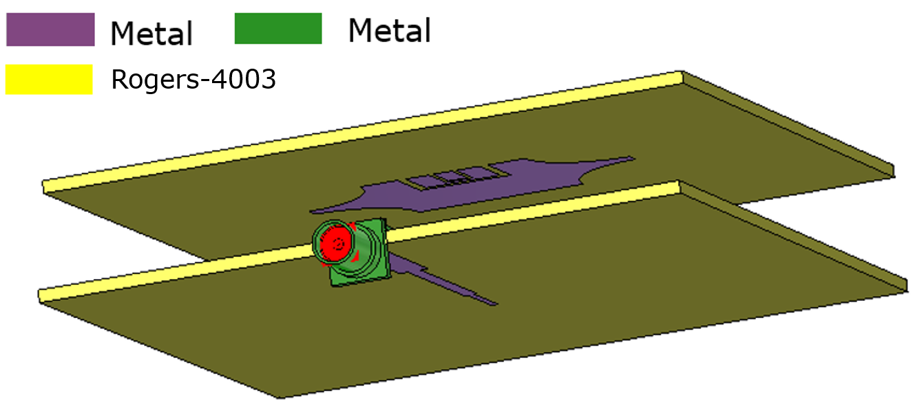
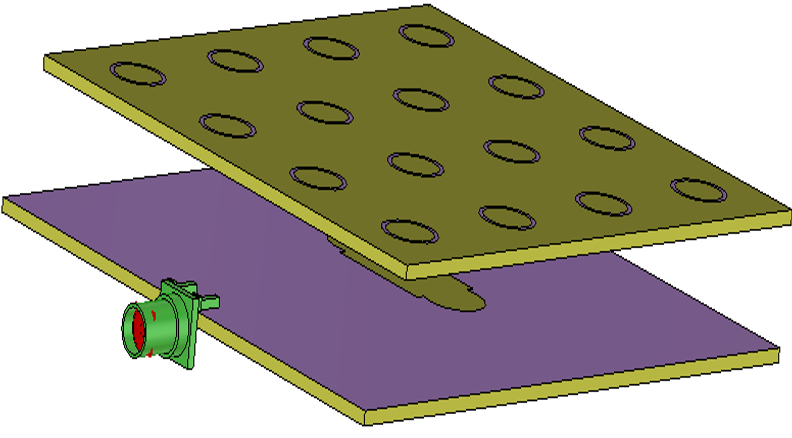
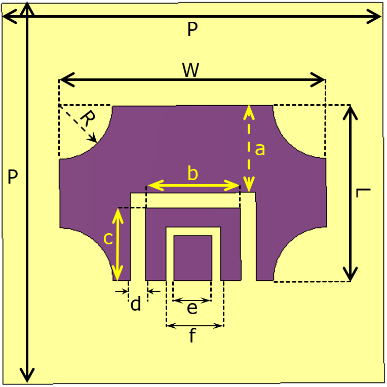
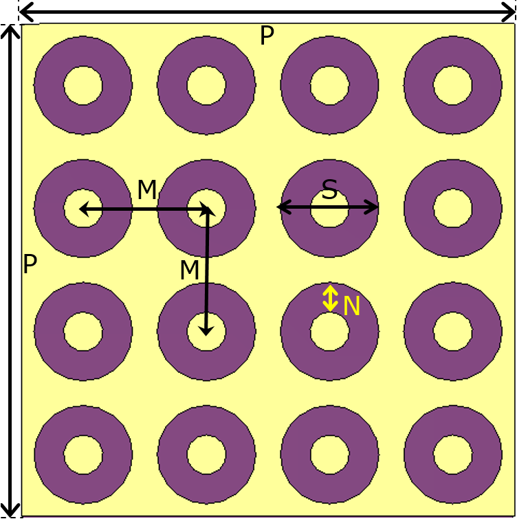
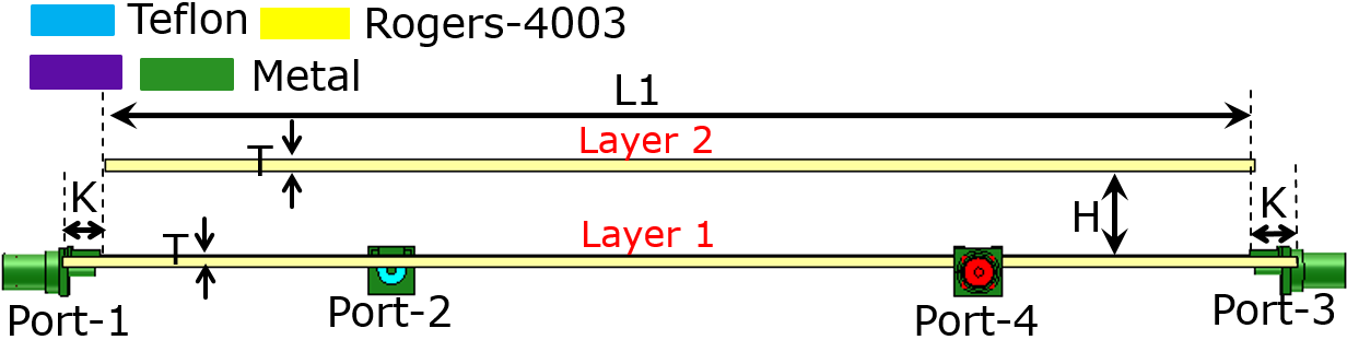
Although the 5G technology can provide reliable wireless communications with a high data rate, low latency, and high data throughput for almost 1 million devices per square kilometer, it highly depends on the quality of the applied antenna. The applied antenna should provide wideband performance to improve the data rate and have a stable high gain over the entire frequency band to ensure reliable communication and avoid penetration reduction. This section presents a radiating element that can be applied to create a MIMO according to the 5G requisites. The perspective views and schematic of the introduced radiating element are displayed in Figs.1(a)-1(b), and Figs.2(a)-2(e). This structure uses the aperture coupled feeding technique, a slotted truncated radiating patch, and a metasurface layer to guarantee wideband and high gain performance. As shown in Fig.2(a), the radiating element consists of two dielectric layers made by Rogers 4003C (=3.55, =0.0027, ), designated by layer 1 and layer 2. The feed line is printed on the back face of layer 1, and the ground plane is printed on the front face of this layer with a dumbbell-shaped slot, which is responsible for coupling the power of the feed line to layer 2, as seen in Figs.2(b)-2(c), respectively. This feeding technique provides excellent isolation between the feed line and layer 2 and allows a very closely independent tuning process of these layers. The dumbbell-shaped slot is used instead of the typical rectangular slot, providing better manipulation of the coupled energy and impedance matching by introducing a new tuning parameter, Rs, as depicted in Fig.2(c). An air gap of H=12.5 mm is inserted between layers to increase the 10-dB bandwidth of the radiating element, as reflected in Fig.2(a). Fig.2(d) illustrates that a rectangular patch with truncated corners and two U-shaped slots is printed at the back of layer 2. The truncating rate, R, is used to tune the impedance of the rectangular patch. The two U-shaped slots provide extra resonances, increasing the impedance bandwidth of the radiating element. A metasurface consisting of ring elements is printed on the front face of layer 2, as shown in Fig.2(e). The inner and outer diameters of ring elements and the number of rings in the array’s horizontal and vertical directions are decided to improve the bandwidth and gain by introducing an extra resonance due to the surface wave propagation in the substrate.
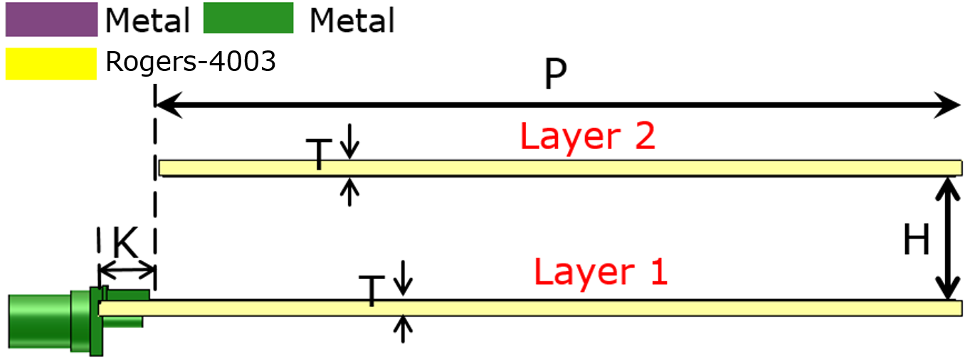
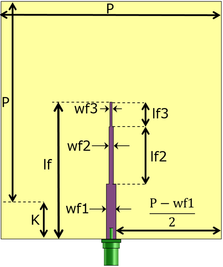
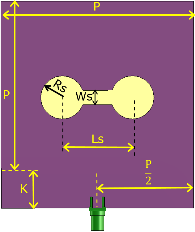
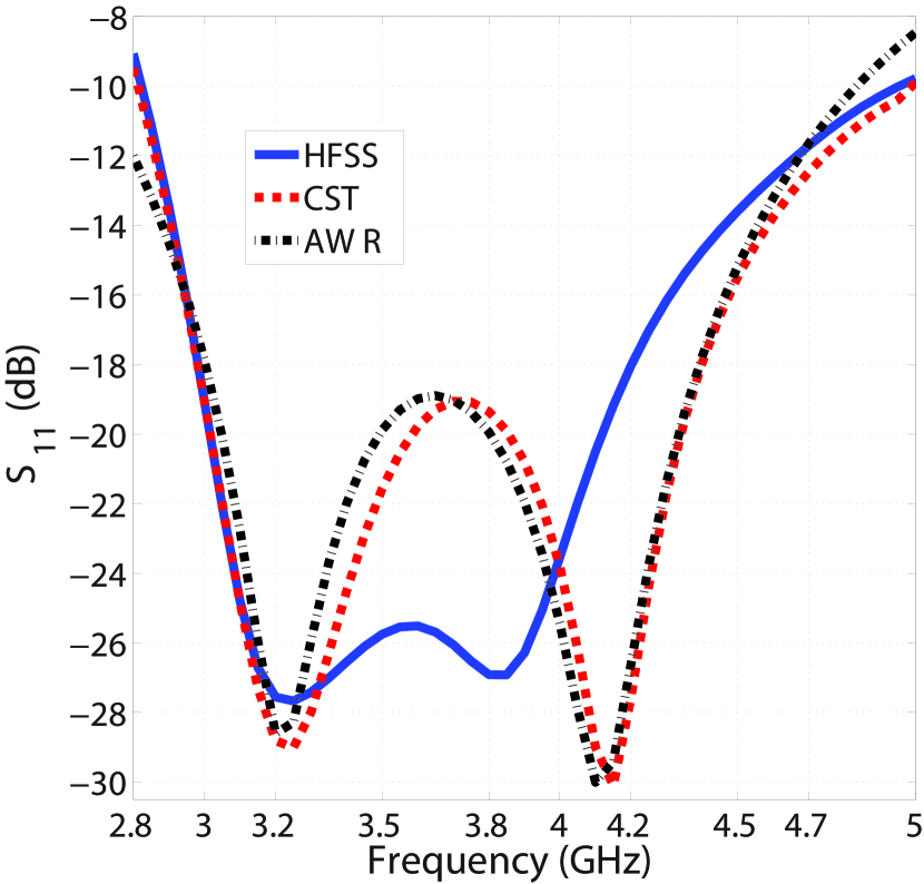
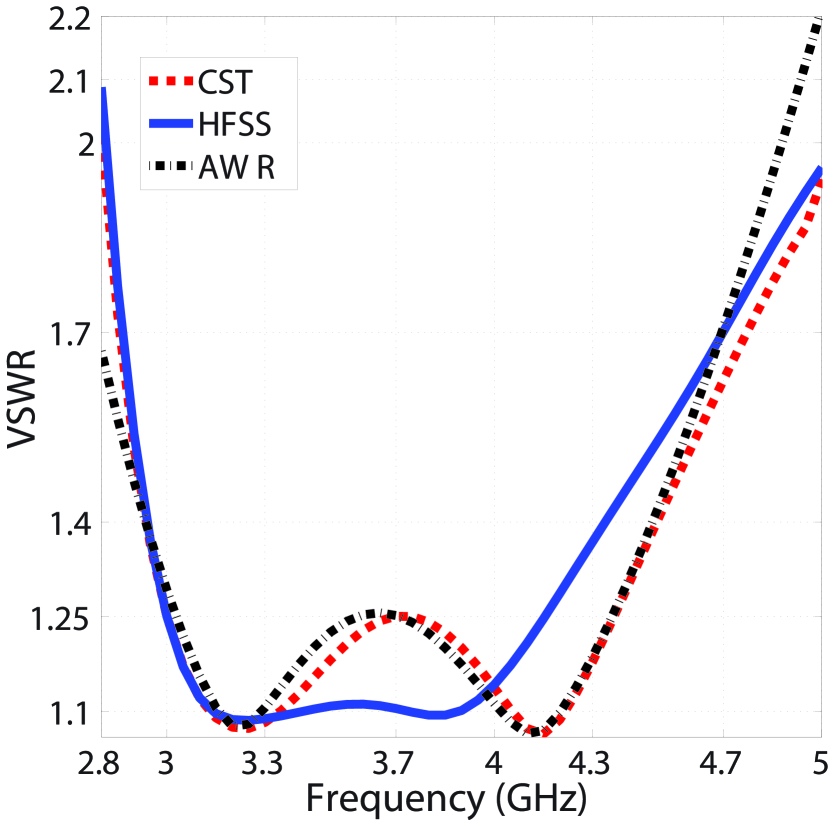
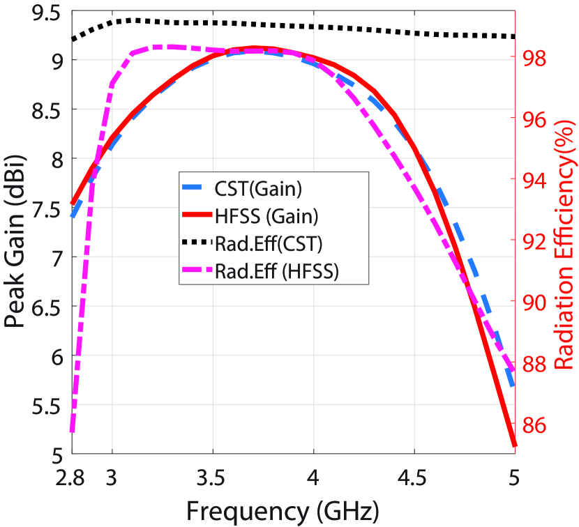
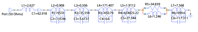
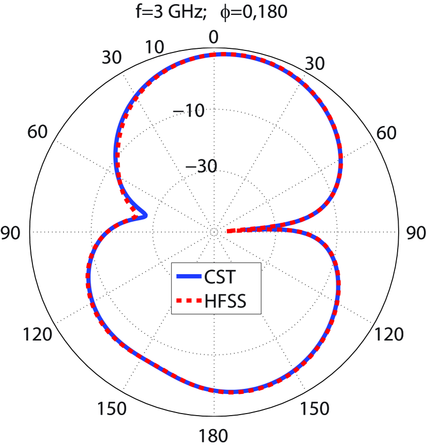
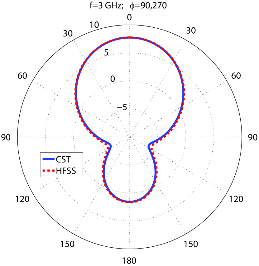
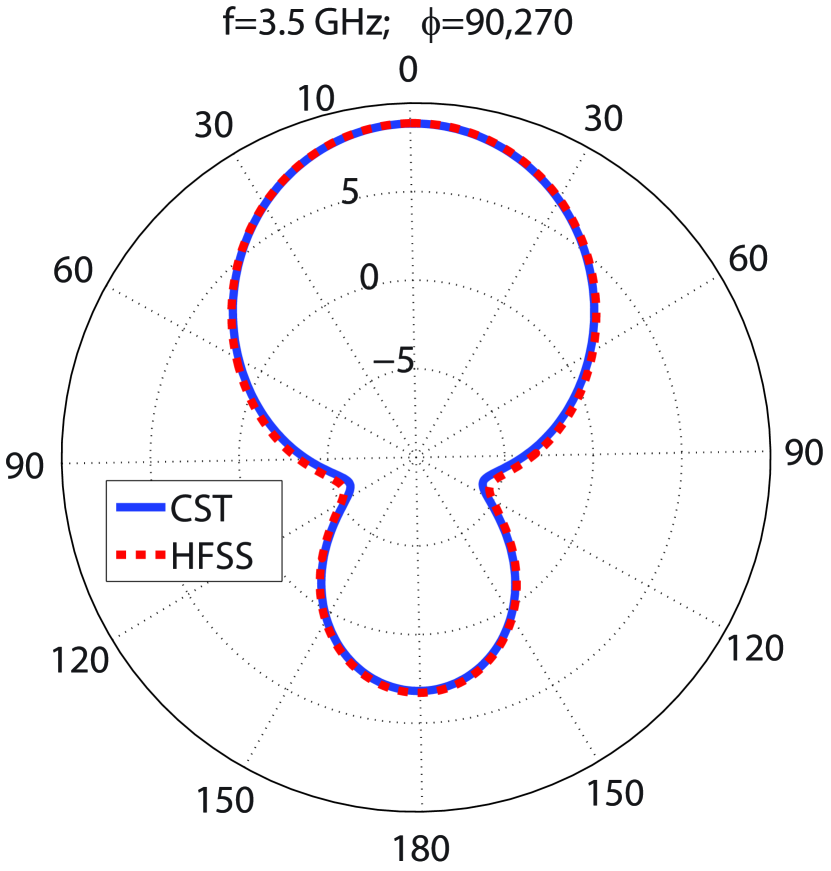
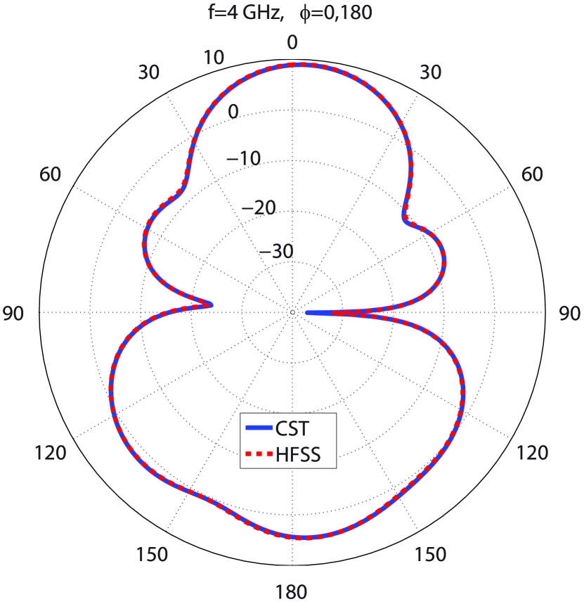
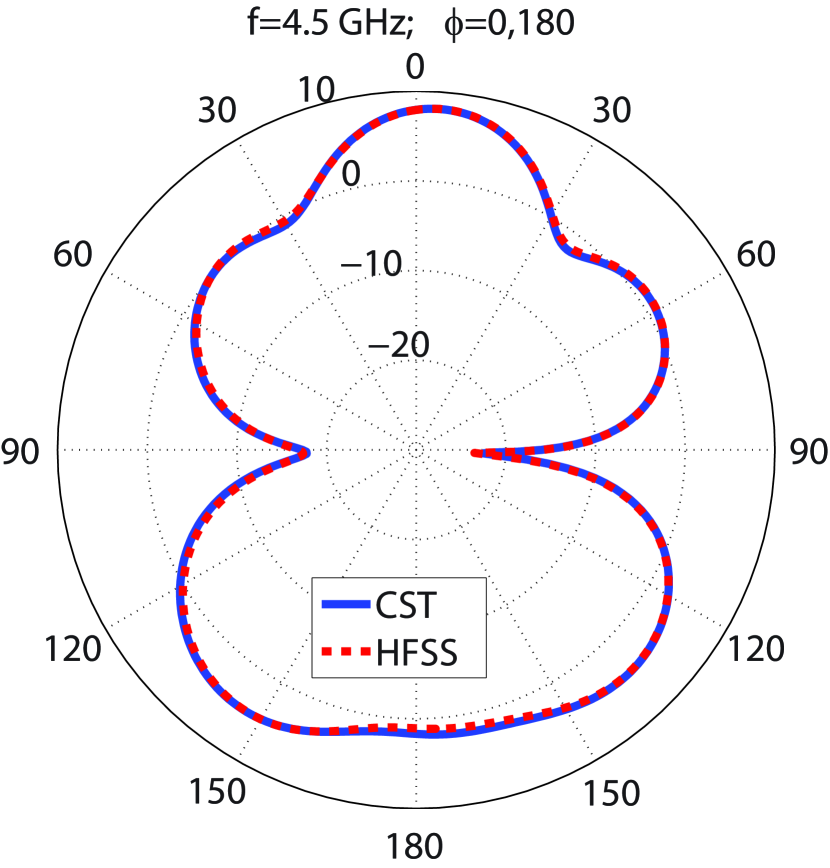
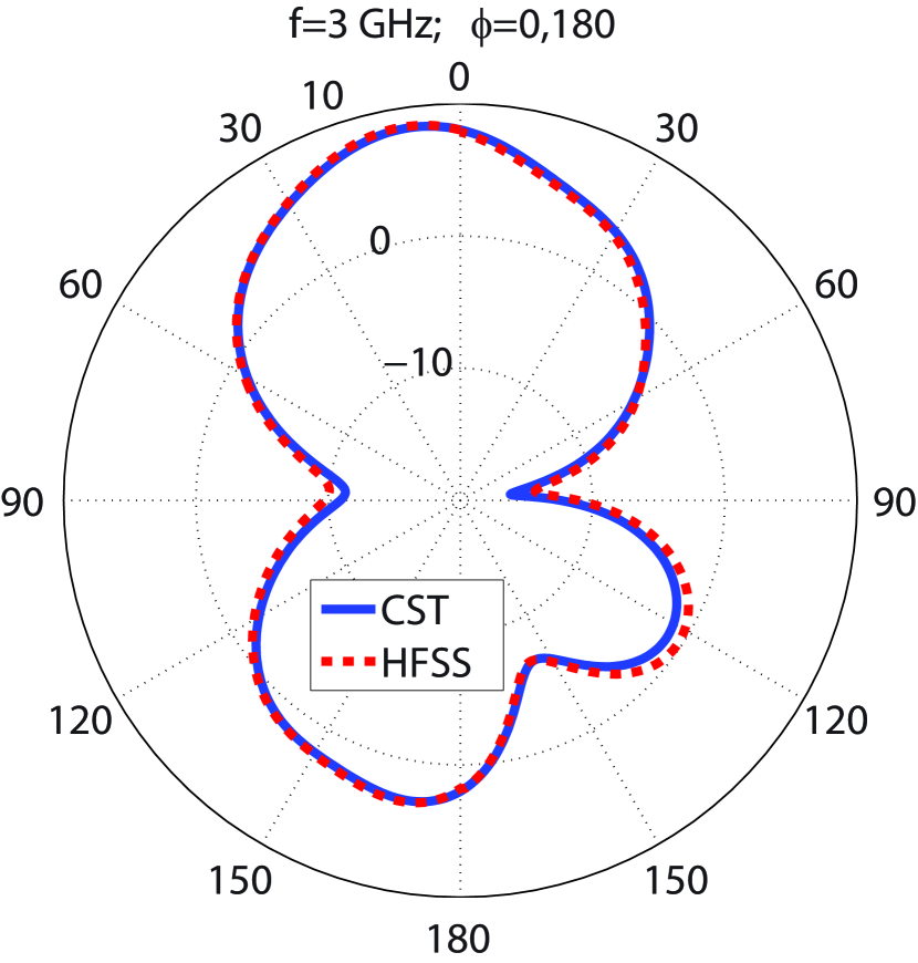
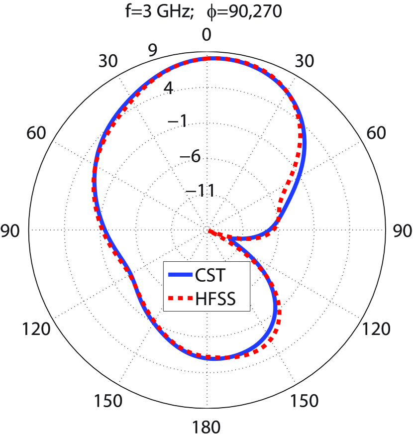
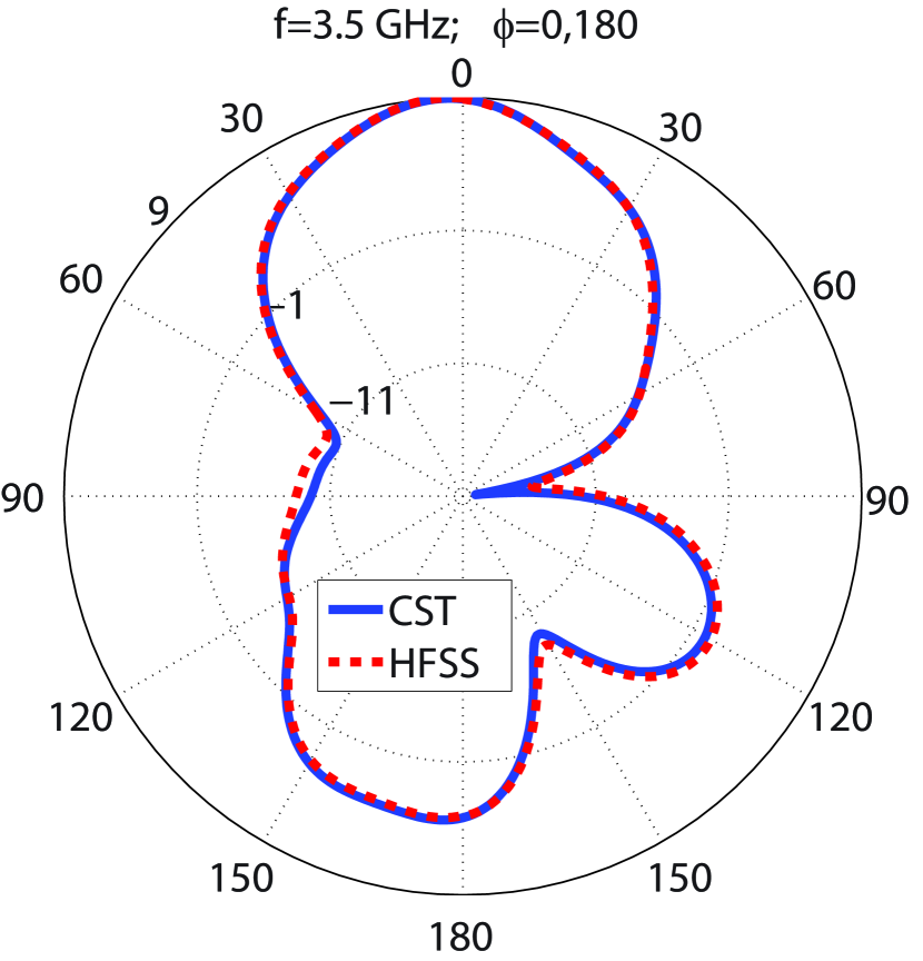
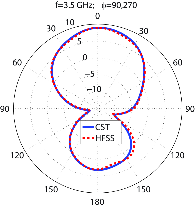
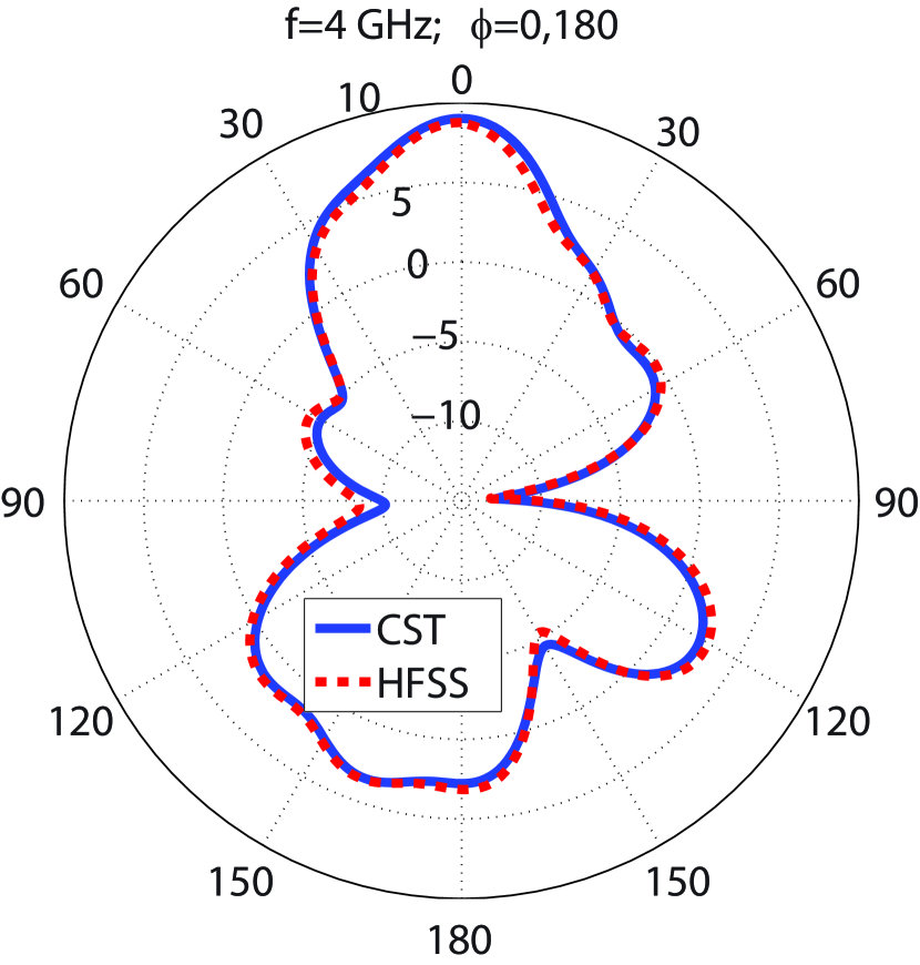
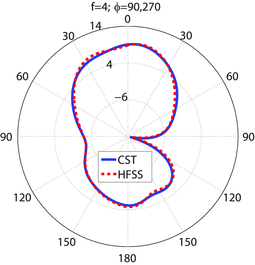
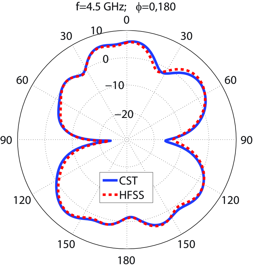
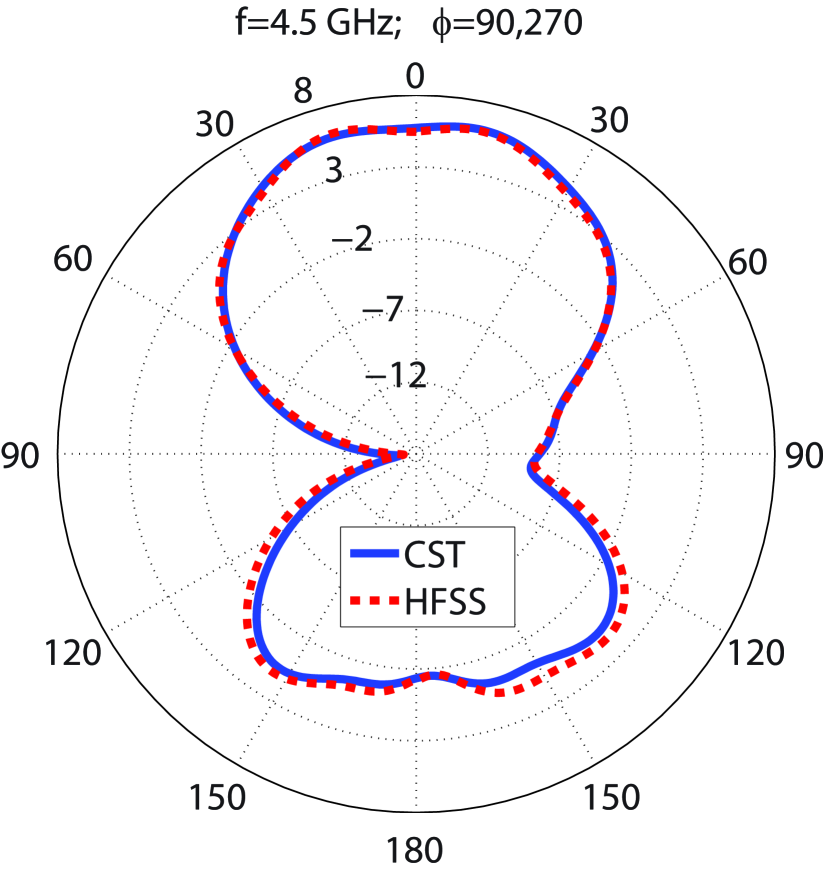
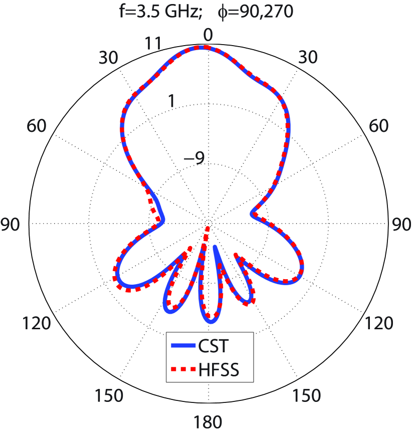
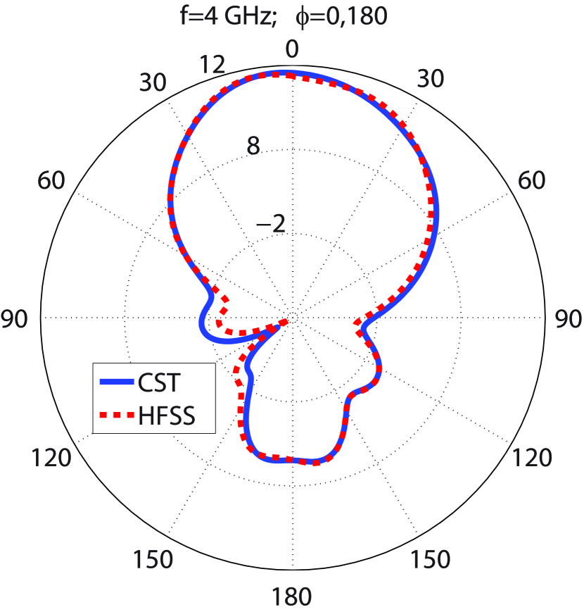
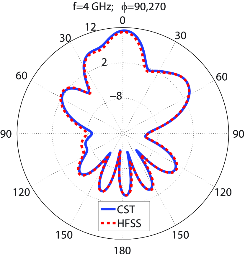
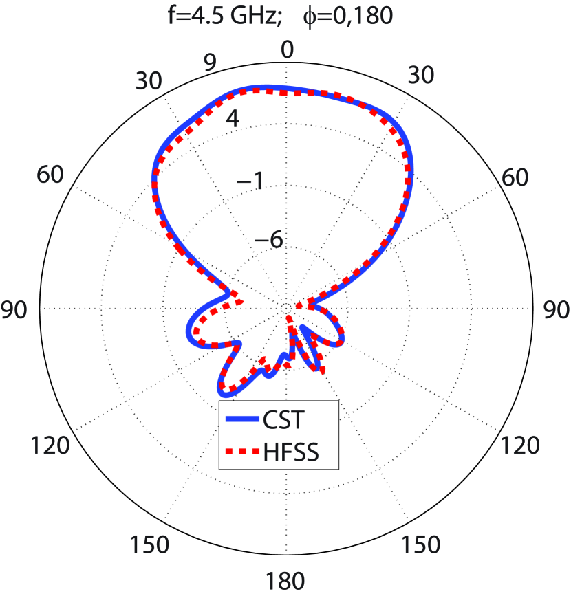
The values of the parameters shown in Figs.2(a)-2(e), indicating the radiating element dimensions, are declared in Table.1. The radiating element is simulated by HFSS and the time domain solver of CST, which apply the FEM (Finite Element Method) and the FIT (Finite Integration Technique) approaches, respectively. As reflected in Figs.3(a)-3(b), the radiating element experiences below -10 dB and VSWR lower than 2 from 2.83 to 4.95 GHz, including the most occupied and in-used frequency bands of the 5G spectrum (3 to 4 GHz and 4.5 to 5 GHz). The simulation results show that the radiating element achieves lower than -19 dB over 3 to 4.3 GHz. As seen in Fig.3(c), the simulated peak gain values calculated by the CST and HFSS software vary from 5.64 to 9.09 dBi and 5.429 to 9.124 dBi, respectively, in the operational bandwidth (2.8-5 GHz). The achieved 8.1 to 9.1 dBi and 5.5 to 8.2 dBi utmost gain values from 3 to 4 GHz and 4.5 to 5 GHz accentuate the potential of designing a high gain MIMO antenna employing the presented radiating element for 5G applications. Moreover, Fig.3(c) shows that the radiating element attains between 86 to 98% and above 98% radiation efficiency from 2.8 to 5 GHz according to HFSS and CST simulation results, respectively. A circuit model consisting of six resonators to approximate the performance of the radiating element is provided in Fig.4. The AWR software is used to simulate the circuit. The obtained and VSWR are in good agreement with the CST simulation results, according to Figs.3(a)-3(b). For more clarification, Figs.5(a)-5(h) provides the far-field gain polar diagrams of the radiating element for E and H planes at 3 GHz, 3.5 GHz, 4 GHz, and 4.5 GHz. The figures show that, the CST and HFSS far-field gains follow each other. However, the CST and HFSS simulation results differ regarding mainly due to different computation methods.
| H (mm) | T (mm) | P (mm) | K (mm) | Wf1 (mm) | Wf2 (mm) | Wf3 (mm) | lf (mm) | lf2 (mm) | lf3 (mm) | Ws (mm) | Ls (mm) | Rs (mm) |
|---|---|---|---|---|---|---|---|---|---|---|---|---|
| 12.5 | 1.524 | 80 | 6 | 3.575 | 1.5317 | 1.476 | 49.591 | 18.21 | 0.614 | 11.712 | 17.13 | 4.8767 |
| R (mm) | W (mm) | L (mm) | a (mm) | b (mm) | c (mm) | d (mm) | e (mm) | f (mm) | M (mm) | S (mm) | N (mm) | – |
| 7.425 | 44.1467 | 18.0627 | 6.69 | 9.276 | 10.755 | 0.618 | 2.178 | 2.85 | 20 | 8.621 | 0.623 | – |


MIMO Antenna Design
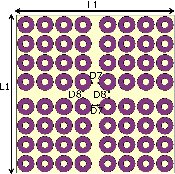
| H (mm) | K (mm) | T (mm) | L1 (mm) | D1 (mm) | D2 (mm) | D3 (mm) | D4 (mm) | D5 (mm) |
|---|---|---|---|---|---|---|---|---|
| 12.5 | 6 | 1.524 | 166 | 17.926 | 30.97 | 34.144 | 24.68 | 42.98 |
| D6 (mm) | D7 (mm) | D8 (mm) | C1 (mm) | B1 (mm) | A1 (mm) | g (mm) | P (mm) | — |
| 42.98 | 17.37 | 17.37 | 81.67 | 64.82 | 54.895 | 4 | 80 | — |


| Ref | -10 dB Bandwidth (GHz) | Peak Gain (dBi) | Isolation (dB) | Num.Ports | Num. Radiating Elements | ECC | Rad.Eff (%) |
| Ref.20 | 3.6-5.3;6.4-10 | 1 to 7 | <-15 | 4 | 4 | <0.0015 | — |
| Ref.21 | 2.7-5.1;5.9-12 | 2.5 to 6 | <-17 | 4 | 4 | — | — |
| Ref.22 | 3.1-10.6 | -3 to 4 | <-20 | 4 | 4 | <0.2 | 92-96 |
| Ref.23 | 3.5-11 | 3.5 to 5.7 | <-20 | 4 | 4 | <0.01 | 70-90 |
| Ref.24 | 2.8-3.3;3.9-11.5 | -3 to 4 | <-18 | 2 | 2 | <0.0003 | — |
| Ref.25 | 3-11.5 | — | <-15 | 2 | 2 | <0.01 | — |
| Ref.26 | 1.66-2.17 | 2.5 to 2.9 | <-10 | 2 | 2 | <0.23 | >96 |
| Ref.27 | 5.8 | 2.5 to 2.9 | <-70 | 2 | 2 | <0.03 | — |
| Ref.28 | 3.3-4.5 | 6.5 to 7.5 | <-15 | 4 | 1 | <0.3 | 84-92 |
| Ref.29 | 2.4 | 2.4 | <-25 | 4 | 4 | <0.03 | 77 |
| Ref.30 | 2.4 | 2.84 | <-58.87 | 4 | 4 | <0.0054 | 90 |
| Ref.31 | 3.4-3.7 | — | <-15 | 8 | 4 | <0.03 | 50-68 |
| Ref.32 | 2.4-2.52;3.66-4;4.62-5.54 | 1 | <-30.5 | 4 | 4 | <0.001 | 85 |
| Ref.33 | 2.34-2.71;3.72-5.10 | 3;3.8 | -18;-21 | 2 | 2 | 0.005;0.001 | 63;67 |
| Ref.34 | 3.27-3.82 | 8.7 | <-32 | 4 | 4 | <0.001 | 92-96 |
| Ref.35 | 4.65-4.97;4.67-4.94 | 1.83 and 1.65 | <-15 | 2 | 2 | <0.02 | 48-53;58-59 |
| Ref.36 | 3.7-4.3 | 3 to 4.1 | <-25 | 2 | 2 | — | — |
| Ref.37 | 3.296-5.962 | -1 to 6.22 | <-50 | 2 | 2 | 0.05 | 42-85 |
| This work without reflector (HFSS) | 2.83-4.7 | 6.55 to 9.7 (2.8-4.7 GHz) | <-34 | 4 | 4 | <0.00022 (2.8-4.7 GHz) | 86 to 98.2 |
| 8.66 to 9.7 (3-4 GHz) | <0.00002 (3-4 GHz) | ||||||
| 6.54 to 6.8 (4.5-4.7 GHz) | |||||||
| This work without reflector (CST) | 2.8-4.68 | 6.2 to 9.41 (2.8-4.7 GHz) | <-35 | 4 | 4 | <0.0002 (2.8-4.7 GHz) | >98 |
| 8.49 to 9.41 (3-4 GHz) | <0.000055 (3-4 GHz) | ||||||
| 6.23 to 6.3 (4.5-4.7 GHz) | |||||||
| This work with reflector (HFSS) | 2.86-4.5 | 9.58 to 11.73 (2.8-4.5 GHz) | <-25 | 4 | 4 | 0.001 | 83 to 98 |
| 10.1 to 11.73 (3-4 GHz) | |||||||
| This work with reflector (CST) | 2.8-4.5 | 8.23 to 11.6 (2.8-4.5 GHz) | <-25 | 4 | 4 | 0.0003 | >98 |
| 10.1 to 11.6 (3-4 GHz) |
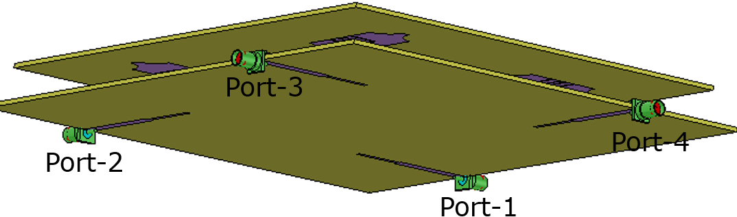
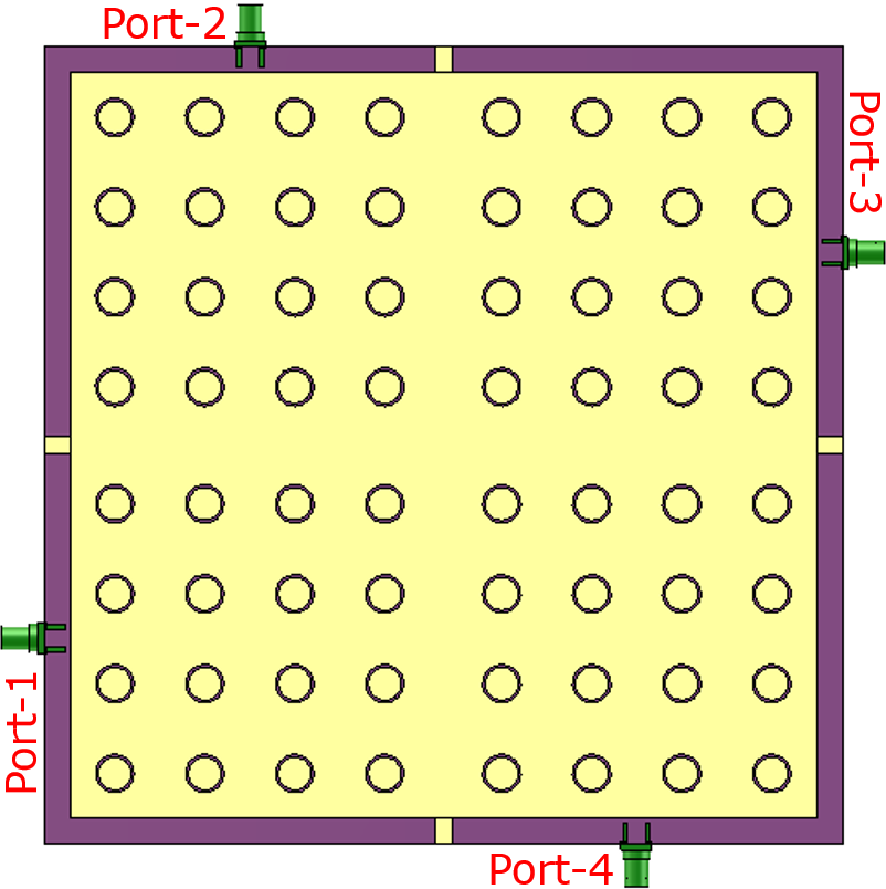
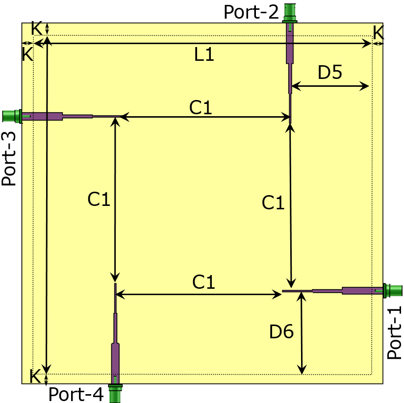
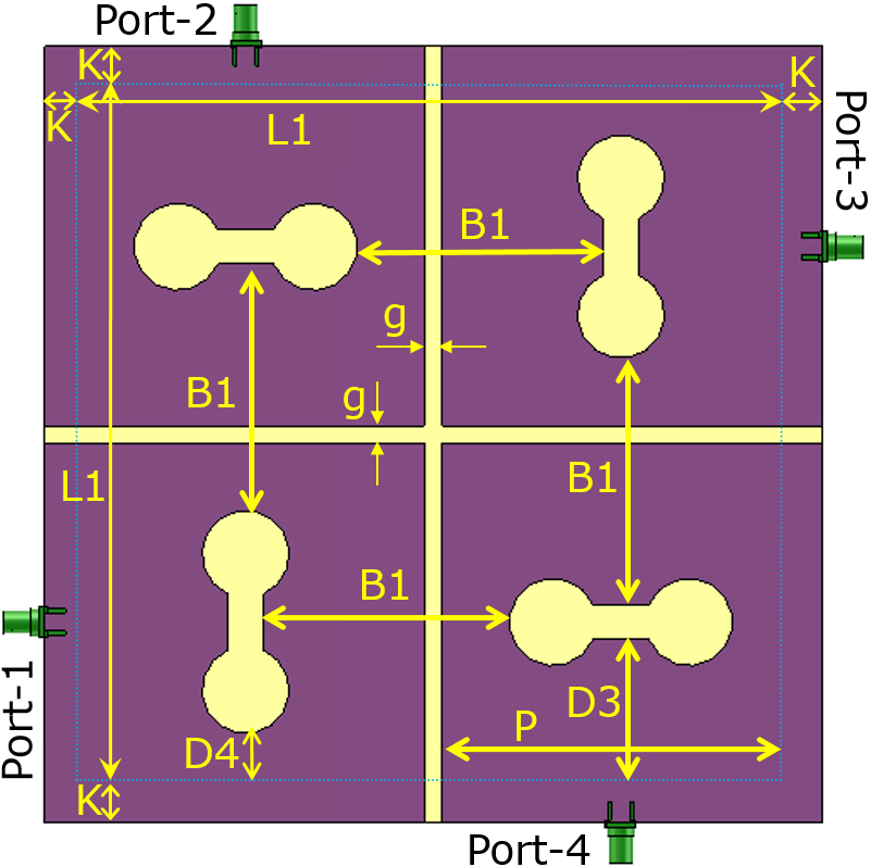
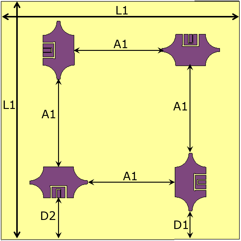
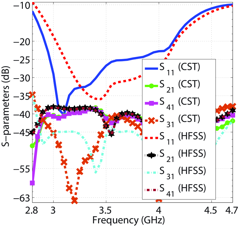
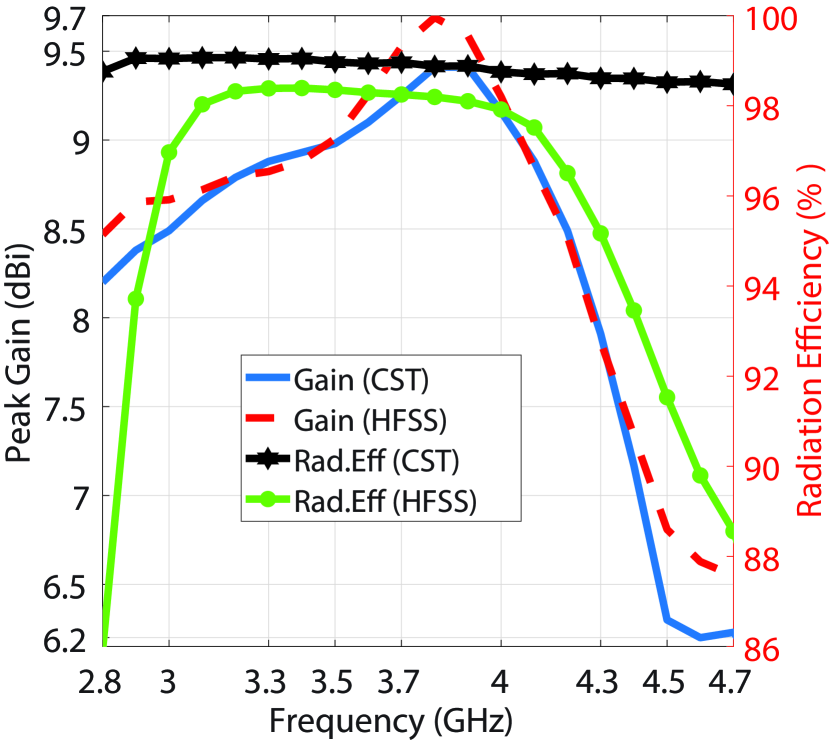
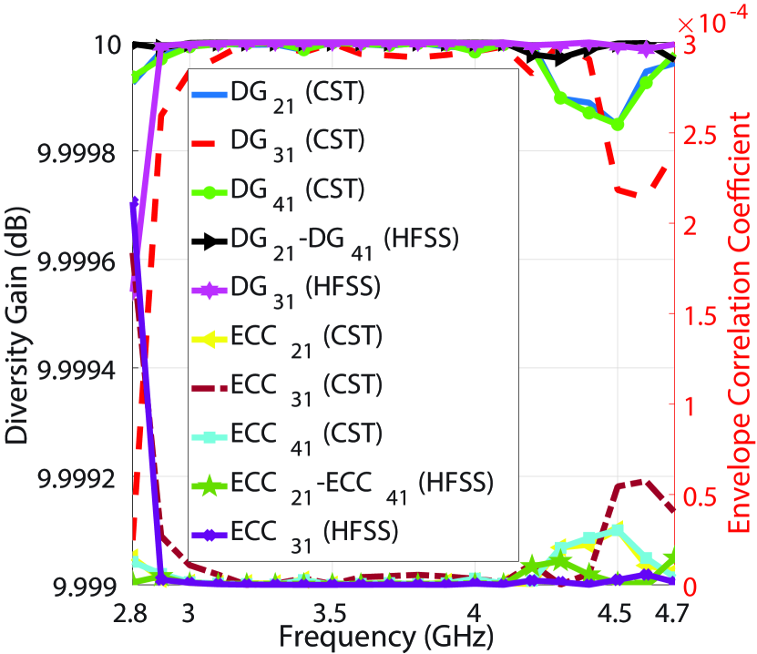
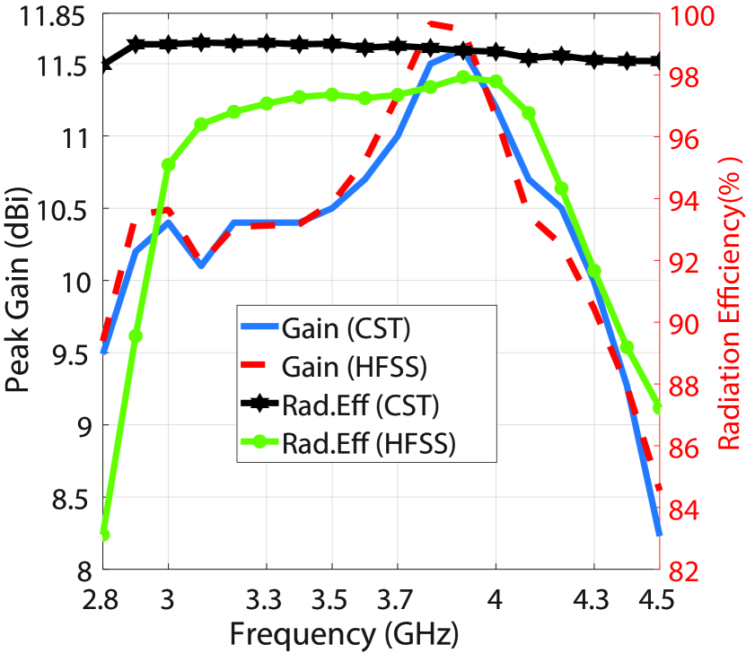
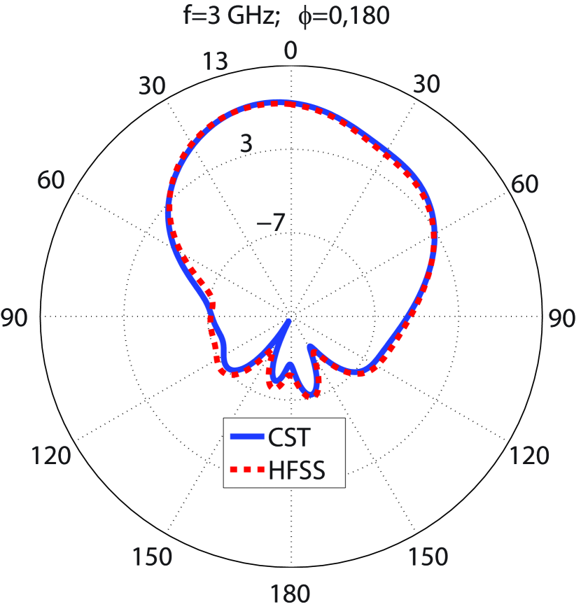
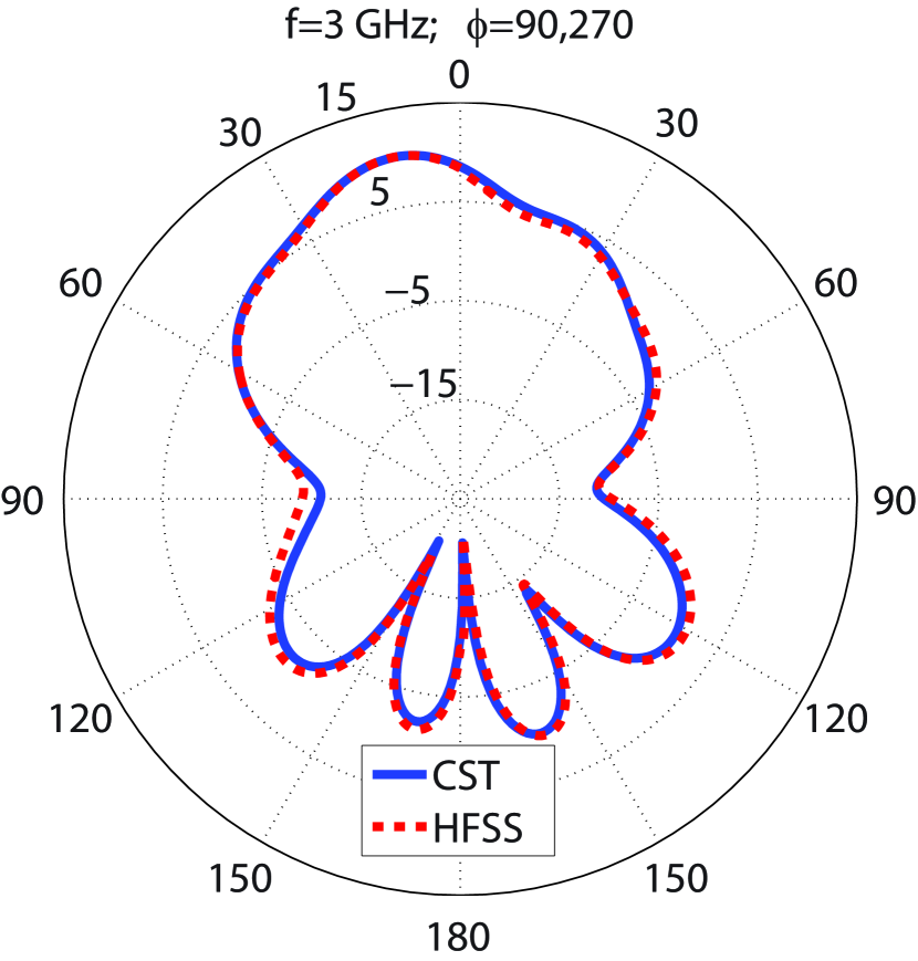
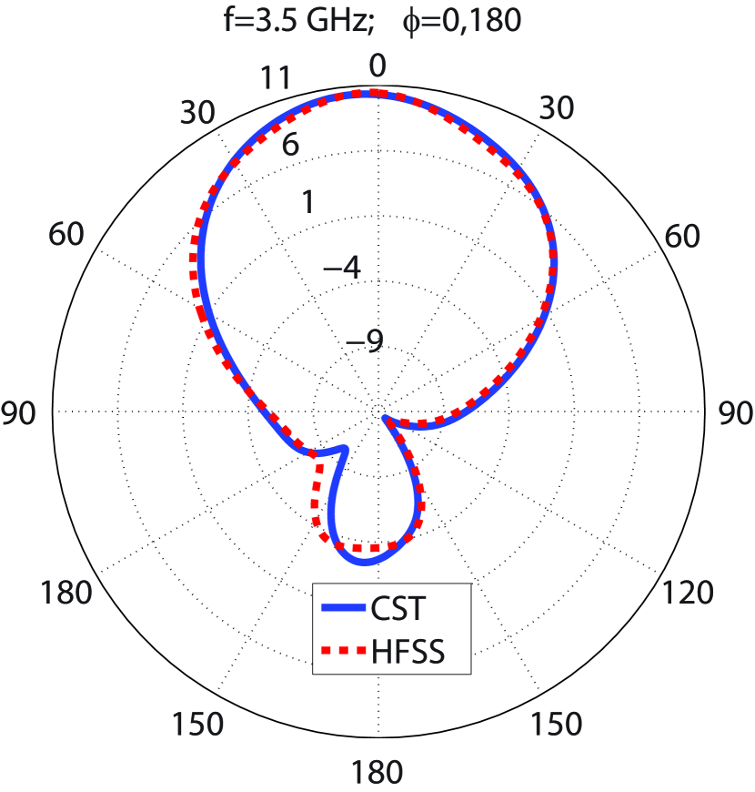
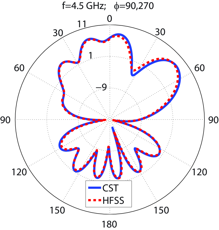
This section develops a MIMO antenna using the radiating element displayed in Figs.1(a)-1(b). The three-dimensional (3D) and schematic views of the MIMO antenna are illustrated in Figs.6(a)-6(c) and Figs.7(a)-7(e). As depicted in figures, the radiating elements constructing the MIMO antenna are placed with , , , and rotation angles like a matrix to produce orthogonal electromagnetic waves, which diminish the coupling between elements. In addition, creating a space of 6 mm between the radiating elements, using the aperture coupled feeding technique , and etching two slots with widths equal to 4 mm in the ground plane of the MIMO structure, as depicted in Fig.7(c), have significantly reduced the coupling effects. Table.2 provides values for the parameters shown in Figs.7(a)-7(e), which indicate the dimensions of the MIMO antenna. The HFSS and the time domain solver of CST simulate the antenna. According to Fig.8(a), the of the design is below -10 dB from 2.8 to 4.7 GHz and below -18 dB from 3 to 4.2 GHz. The CST and HFSS results show that the isolation between ports varies from -63 to -35 dB and -56 to -34 dB from 2.8, respectively, in the operational bandwidth (2.8 to 4.7 GHz). Therefore, the presented MIMO structure enjoys magnificent isolation levels between ports. It is worth mentioning that the symmetry of the proposed design leads to identical results for other ports, so it is redundant to show for , , , , , , , , , , , and in Fig.8(a). Fig.8(b) depicts the maximum gain and radiation efficiency values as a function of the frequency. According to the CST and HFSS results, the highest gain values change from 5.97 to 9.41 dBi and 6.55 to 9.7 dBi by changing the frequency from 2.8 to 4.7 GHz, respectively, as seen in Fig.8(b). The antenna’s utmost gain values run from 8.49 to 9.41 dBi and 6.23 to 6.3 dBi by changing the frequency from 3 to 4 GHz and 4.5 to 4.7 GH, respectively, according to CST results and they go from 8.66 to 9.7 dBi and 6.54 to 6.8 dBi for 3 to 4 GHz and 4.5 to 4.7 GHz, respectively, according to HFSS results. In addition, the presented design obtains 86 to 98.2% and above 98% radiation efficiency, respectively, according to HFSS and CST simulation results from 2.8 to 4.7 GHz. The diversity gain (DG) and ECC are essential factors determining how independent the radiating elements of a MIMO antenna work. The simulation results of ECC and diversity gain for other ports should be addressed due to the symmetry of the presented design. The CST results for ECC and DG are computed based on the far-field results. In contrast, the HFSS results are calculated according to the scattering parameters using Eqs.1-2 Ref.38. Obtaining less than ECC and nearly 10 dB DG from 3 to 4.7 GHz ensures that the radiating elements of the MIMO antenna work independently, and Fig.8(c) reflects it. The far field gain patterns at 3, 3.5, 4, and 4.5 GHz for E and H planes are illustrated in Figs.9(a)-9(h). The figures show that the CST and HFSS radiation patterns are in good agreement and are almost stable.
| (1) |
| (2) |
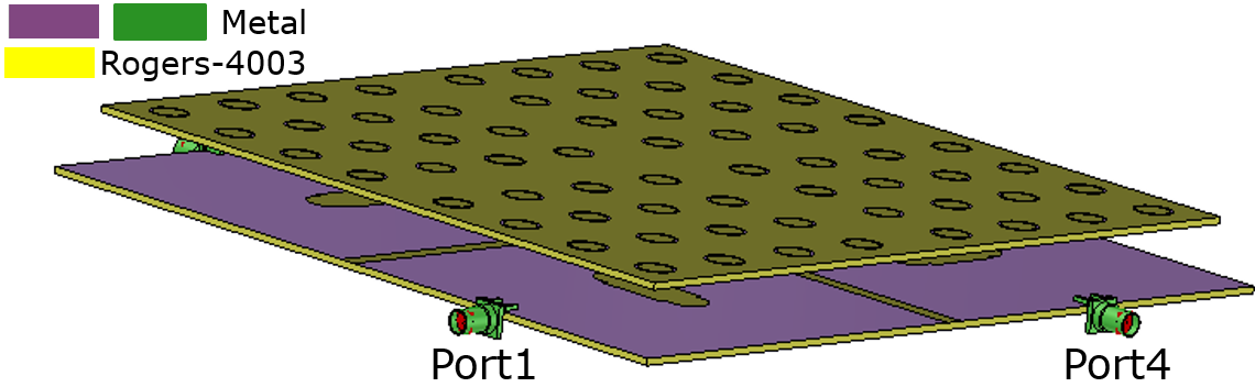
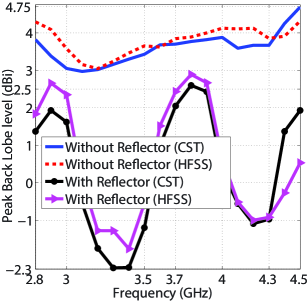
The polar gain patterns show that the design suffers from acceptable back lobe levels of 3 to 4.75 dBi over 3 to 4.5 GHz due to the aperture-coupled feeding technique. A metal plate is placed 20 mm beneath the MIMO antenna to kill the undesired back lobe levels by creating a semi-cavity. The HFSS and CST are applied to simulate the design. The simulation results indicate that the antenna attains lower than -10 dB from 2.85 to 4.5, including 3 to 4 GHz and excluding 4.5 to 5 GHz of the 5G spectrum, as shown in Fig.10(a). The antenna experiences below -22.36 and -15 dB from 3 to 4 GHz, according to CST and HFSS results, respectively. As seen in Fig.10(a), the isolation between ports varies from -50 to -25 dB by changing the frequency from 2.8 to 4.5 GHz, which is deteriorated in comparison with when the reflector is not used, as depicted in Fig.8(a). However, the isolation results are still perfect and acceptable. In addition, adding the reflector plate has resulted in losing the impedance matching in one of the 5G frequency bands from 4.5 to 4.7 GHz. According to the CST and HFSS simulation results, the maximum gain values change from 8.23 to 11.6 dBi and 9.58 to 11.73 dBi, respectively, by varying the frequency from 2.8 to 4.5 GHz, as depicted in Fig.10(b). Compared with Fig.8(b), the metal plate has significantly increased the antenna gain by killing the backward propagation power and converting it to the forward propagation power, which boosts the forward radiation. In addition, the antenna achieves 82 to 98% and above 98% radiation efficiency, according to HFSS and CST simulation results, respectively, in the operational bandwidth. A comparison with the radiation efficiency provided in Fig.8(b) shows that adding a reflector worsens the efficiency slightly, but the results are still perfect. Compared with Fig.8(b), although adding the reflector has slightly deteriorated ECC and DG values, the radiating elements work independently, and there is very low mutual coupling between the elements. As seen in Fig.10(c), the antenna achieves almost 10 dB DG and less than 0.001 ECC in the operational bandwidth.
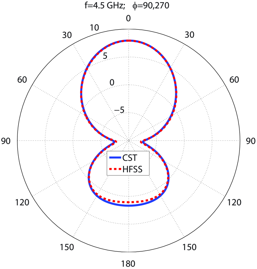
The polar far field gain diagrams of the MIMO antenna with reflector for E and H planes at 3, 3.5, 4, and 4.5 GHz are shown in Figs.11(a)-11(h). Comparing with Figs.9(a)-9(h), the back lobe levels are reduced, and the gain values are increased significantly. For clarification, the maximum back lobe levels of the MIMO antenna with and without employing the reflector plate are compared in Fig.12. According to CST and HFSS results, when the reflector plate is used, the back lobe levels vary from -2.3 to 2.5 dBi and -2 to 3 dBi from 3 to 4.5 GHz, respectively. However, the antenna experiences 3 to 4.75 dBi back lobe levels without employing the reflector plate. These results are testimony that the presented MIMO designs ( with/without the reflector plate) are one of the best choices for 3 to 4 GHz and 4.5 to 4.7 GHz 5G applications regarding high gain, high radiation efficiency, low mutual coupling between elements and high isolation between ports, which guarantee the demonstration of a reliable 5G wireless communication with high data rate, increased channel capacity, low multipath fading effects, and high data throughput, and maintain its penetration rate. It is relevant to mention that the differences between the CST and HFSS results are due to using different computational methods (FEM and FIT) for simulating the antenna.
An analogy between the presented MIMO antennas and other studies is provided in Table.3. The presented MIMO design works from 2.8 to 4.5 GHz when the reflector plate is used and works from 2.8 to 4.7 GHz when the reflector is not employed, including 3 to 4 GHz and 4.5 to 4.7 GHz, two frequency bands of the 5G spectrum. Regarding the bandwidth, the proposed antennas perform better than Refs.26, 27, 28, 29, 30, 31, 34, 35, 36. As the purpose of the study has been to bring forward a high gain and highly isolated MIMO design to operate from 3 to 4 GHz, the middle band of the 5G spectrum where many technologies offer their 5G services, and the presented MIMO design have reached this goal, other studies that work in a broader frequency spectrum do not belittle the achievements of the presented MIMO structure. Concerning the gain, the antenna performs better than the studies mentioned in Table.3. As 5G needs high gain antennas to maintain the signal quality, increase its robustness against noise signals, increase its reliability, send more directed power to avoid the loss of penetration and transfer data over longer distances, the presented MIMO antenna can be considered as a solution for these critical issues. Concerning the isolation, the antenna performs superior to the studies in Table.3 except for Refs.27, 30, 37 without using the reflector plate. If the antenna employs the reflector plate, its isolation deteriorates. However, it still experiences acceptable isolation and performs better than other studies, excluding Refs.27, 30, 32, 34, 37. The proposed antenna has the lowest ECC among the studies mentioned in Table.3. The highly isolated ports and less than 0.001 ECC show that the antenna experiences low mutual couplings between the radiating elements, achieving high channel capacity, one of the requisites of the 5G technology. Concerning the radiation efficiency, the CST results show that the proposed designs perform better than the studies provided in Table.3 by attaining more than 98% efficiency. However, Refs.21, 26, 30, 34 experience higher radiation efficiency in some frequencies, according to HFSS results. The achievements of the proposed MIMO design have made it one of the best candidates for 5G applications, and the above comparison verifies this.
Conclusion
This study puts forward two wideband, high gain, highly efficient metasurface-based MIMO antennas for 5G applications. The first antenna operates from 2.8 to 4.7 GHz, including the middle and a portion of the upper bands of the 5G spectrum, where the majority of 5G technologies offer their services. The second antenna puts a reflector plate at 20 mm beneath the first antenna to kill the backward propagation power and convert it to the forward propagation power, strengthening the total forward propagation power from 2.8 to 4.5 GHz, including the middle band of the 5G frequency range. The radiating elements of the presented MIMO antennas use the aperture coupled feeding technique with a dumbbell-shaped slot etched on the ground plane, a truncated rectangular patch with two U-shaped slots, and a metasurface layer. A matrix of these radiating elements constructs the MIMO antennas, which are placed with , , , and rotation angles, and two horizontal and vertical strip slots are engraved on the ground of the MIMO antenna to create the decoupling structure. The antenna is simulated using the CST and the HFSS software. The CST and HFSS simulation results indicate that the highest gain values of the first MIMO antenna vary from 6.2 to 9.41 dBi and 6.5 to 9.7 dBi, respectively, while experiencing 3 to 4.75 dBi peak back lobe levels. The second antenna achieves 8.23 to 11.6 dBi and 9.58 to 11.73 dBi maximum gain values, according to the CST and HFSS simulation results, respectively. Due to using a reflector plate, the second antenna experiences -2.3 to 3 dBi utmost back lobe levels, which are significantly lower than the first MIMO antenna. The first and the second antenna use the aperture-coupled feeding technique and two strip slots to reach isolation values below -35 and -25 dB over the operational bandwidth, respectively. Both antennas enjoy almost 10 dB diversity gain and below 0.0002 (first antenna) and 0.001 (second antenna) ECC values. The results testify to the highly independent performances of the radiating elements constructing the MIMO antennas. The proposed designs satisfy the 5G requisites by providing wideband, high gain, highly efficient, high isolation, minimal ECC level, and almost 10 dB diversity gain, which make it possible to achieve high channel capacity, high data rate, high signal quality, high reliability, low multi-pass fading effects and to avoid the penetration loss. The comparison of the achievements of the proposed antennas with other studies shows that the proposed antennas are one of the best choices for 5G applications.
Data Availability
Data underlying the results will be available upon request.
Additional information
Authors proclaim no conflict of interest.
References
- [1] Hajlaoui, E. et al. 4g and 5g technologies: A comparative study. \JournalTitle2020 5th International Conference on Advanced Technologies for Signal and Image Processing (ATSIP) 1–6 (2020).
- [2] Song, L., Xu, Z., Tian, Z., Chen, J. & Zhi, R. Research on 4g and 5g authentication signaling. \JournalTitleJournal of Physics: Conference Series 1213, 42–48, DOI: 10.1088/1742-6596/1213/4/042048 (2019).
- [3] Choi, Y.-i., Kim, J.-H. & Park, N.-I. Revolutionary direction for 5g mobile core network architecture. \JournalTitle2016 International Conference on Information and Communication Technology Convergence (ICTC) 51, 992–996, DOI: 10.1109/ICTC.2016.7763350 (2016).
- [4] Elnashar, A. & El-Saidny, M. A. Practical guide to lte-a, volte and iot: Paving the way towards 5g-chapter 8. \JournalTitleJohn Wiley & Sons 382–443, DOI: 10.1002/9781119063407.ch8 (2018).
- [5] Kumar, S., Dixit, A. S., Malekar, R. R., Raut, H. D. & Shevada, L. K. Fifth generation antennas: A comprehensive review of design and performance enhancement techniques. \JournalTitleIEEE Access 8, 163568–163593, DOI: 10.1109/ACCESS.2020.3020952 (2020).
- [6] Huang, H.-C. Overview of antenna designs and considerations in 5g cellular phones. \JournalTitle2018 International Workshop on Antenna Technology (iWAT) 8, 1–4, DOI: 10.1109/IWAT.2018.8379253 (2018).
- [7] Hong, W. et al. Multibeam antenna technologies for 5g wireless communications. \JournalTitleIEEE Transactions on Antennas and Propagation 65, 6231–6249, DOI: 10.1109/LAWP.2022.3189073 (2017).
- [8] Series, M. Guidelines for evaluation of radio interface technologies for imt-2020. \JournalTitleReport ITU 2512 (2017).
- [9] Sarade, S. S. & Ruikar, S. Development of multiband mimo antenna with defective ground structure. \JournalTitleProcedia Computer Science 171, 1829–1838, DOI: 10.1016/j.procs.2020.04.196 (2020).
- [10] Sharma, P., Tiwari, R. N., Singh, P., Kumar, P. & Kanaujia, B. K. Mimo antennas: Design approaches, techniques and applications. \JournalTitleSensors 22, 7813, DOI: 10.3390/s22207813 (2022).
- [11] Ahmad, A., Choi, D.-y. & Ullah, S. A compact two elements mimo antenna for 5g communication. \JournalTitleScientific Reports 12, 3608, DOI: 10.1038/s41598-022-07579-5 (2022).
- [12] Matin, M. A. Wideband, multiband, and smart reconfigurable antennas for modern wireless communications. \JournalTitleIGI Global 1–421, DOI: 10.1038/s41598-022-07579-5 (2015).
- [13] Hussain, R., Alreshaid, A. T., Podilchak, S. K. & Sharawi, M. S. Compact 4g mimo antenna integrated with a 5g array for current and future mobile handsets. \JournalTitleIET microwaves, antennas & propagation 11, 271–279, DOI: 10.1049/iet-map.2016.0738 (2017).
- [14] Patil, A. & Bhadade, R. S. A literature survey on mimo antenna. \JournalTitleProceedings of the International Conference on IoT Based Control Networks & Intelligent Systems - ICICNIS 2021 (2021).
- [15] Si, L., Jiang, H., Lv, X. & Ding, J. Broadband extremely close-spaced 5g mimo antenna with mutual coupling reduction using metamaterial-inspired superstrate. \JournalTitleOptics express 27, 3472–3482, DOI: 10.1364/OE.27.003472 (2019).
- [16] Bliss, D. W., Forsythe, K. W. & Chan, A. M. Mimo wireless communication. \JournalTitleLincoln Laboratory Journal 15, 97–126 (2005).
- [17] Rosaline, I., Kumar, A., Upadhyay, P. & Murshed, A. H. Four element mimo antenna systems with decoupling lines for high-speed 5g wireless data communication. \JournalTitleInternational Journal of Antennas and Propagation 2022, DOI: 10.1155/2022/9078929 (2022).
- [18] Rosaline, I., Kumar, A., Upadhyay, P. & Murshed, A. H. Four element mimo antenna systems with decoupling lines for high-speed 5g wireless data communication. \JournalTitleInternational Journal of Antennas and Propagation 2022, DOI: 10.1155/2022/9078929 (2022).
- [19] Nabi Alsath, M. G., Sowjanya, P. D., Kirubaveni, S. & Indu, V. Optically transparent mimo antenna with polarization diversity for vehicular communications. \JournalTitleInternational Journal of Electronics DOI: 10.1080/00207217.2023.2221456 (2023).
- [20] Kiem, N. K., Phuong, H. N. B., Chien, D. N. et al. Design of compact 4 4 uwb-mimo antenna with wlan band rejection. \JournalTitleInternational Journal of Antennas and Propagation 2014, DOI: 10.1155/2014/539094 (2014).
- [21] Khan, M. et al. Compact 4 4 uwb-mimo antenna with wlan band rejected operation. \JournalTitleElectronics Letters 51, 1048–1050, DOI: 10.1049/el.2015.1252 (2015).
- [22] Amin, F. et al. A compact quad-element uwb-mimo antenna system with parasitic decoupling mechanism. \JournalTitleapplied sciences 9, 2371, DOI: 10.3390/app9112371 (2019).
- [23] Abdelghany, M. A., Sree, M. F. A., Desai, A. & Ibrahim, A. A. 4-port octagonal shaped mimo antenna with low mutual coupling for uwb applications. \JournalTitleCMES-Computer Modeling in Engineering & Sciences 9, 1999–2015, DOI: 10.32604/cmes.2023.023643 (2023).
- [24] Ibrahim, A. A., Machac, J. & Shubair, R. M. Compact uwb mimo antenna with pattern diversity and band rejection characteristics. \JournalTitleMicrowave and Optical Technology Letters 59, 1460–1464, DOI: 10.1002/mop.30564 (2017).
- [25] IIbrahim, A. A., Machac, J., Shubair, R. M. & Svanda, M. Compact uwb mimo antenna with asymmetric coplanar strip feeding configuration. \JournalTitle2017 IEEE 28th Annual International Symposium on Personal, Indoor, and Mobile Radio Communications (PIMRC) 1–4, DOI: 10.1109/PIMRC.2017.8292768 (2017).
- [26] Malviya, L., Panigrahi, R. K. & Kartikeyan, M. V. Four element planar mimo antenna design for long-term evolution operation. \JournalTitleIETE Journal of Research 64, 367–373, DOI: 10.1080/03772063.2017.1355755 (2018).
- [27] Mohamed, I., Abdalla, M. & Mitkees, A. E.-A. Perfect isolation performance among two-element mimo antennas. \JournalTitleAEU-International Journal of Electronics and Communications 107, 21–31, DOI: 10.1016/j.aeue.2019.05.014 (2019).
- [28] Wong, K.-L., Chen, J.-Z. & Li, W.-Y. Four-port wideband annular-ring patch antenna generating four decoupled waves for 5g multi-input–multi-output access points. \JournalTitleIEEE Transactions on Antennas and Propagation 69, 2946–2951, DOI: 10.1109/TAP.2020.3025237 (2020).
- [29] Elfergani, I. et al. Low-profile and closely spaced four-element mimo antenna for wireless body area networks. \JournalTitleElectronics 9, 258, DOI: 10.3390/electronics9020258 (2020).
- [30] Suganya, E. et al. An isolation improvement for closely spaced mimo antenna using /4 distance for wlan applications. \JournalTitleInternational Journal of Antennas and Propagation 2023, 251, DOI: 10.1155/2023/4839134 (2023).
- [31] Ji, Z. et al. Low mutual coupling design for 5g mimo antennas using multi-feed technology and its application on metal-rimmed mobile phones. \JournalTitleIEEE Access 9, 151023–151036, DOI: 10.1109/ACCESS.2021.3126640 (2021).
- [32] Dileepan, D., Natarajan, S. & Rajkumar, R. A high isolation multiband mimo antenna without decoupling structure for wlan/wimax/5g applications. \JournalTitleProgress In Electromagnetics Research C 112, 207–219, DOI: 10.2528/PIERC21032605 (2021).
- [33] Xi, S., Cai, J., Shen, L., Li, Q. & Liu, G. Dual-band mimo antenna with enhanced isolation for 5g nr application. \JournalTitleMicromachines 14, 95, DOI: 10.3390/mi14010095 (2022).
- [34] Sufian, M. A. et al. Isolation enhancement of a metasurface-based mimo antenna using slots and shorting pins. \JournalTitleIEEE Access 9, 73533–73543, DOI: 10.1109/ACCESS.2021.3079965 (2021).
- [35] Desai, A. et al. Transparent 2-element 5g mimo antenna for sub-6 ghz applications. \JournalTitleElectronics 11, 251, DOI: 10.3390/electronics11020251 (2022).
- [36] Tran, H.-H., Nguyen, T. T.-L., Ta, H.-N. & Pham, D.-P. A metasurface-based mimo antenna with compact, wideband, and high isolation characteristics for sub-6 ghz 5g applications. \JournalTitleIEEE Access 2023, 67737 – 67744, DOI: 10.1109/ACCESS.2023.3292303 (2023).
- [37] flower-shaped miniaturized UWB-MIMO antenna with high isolation, A. Mu, weidong and lin, han and wang, zhonggen and li, chenlu and yang, ming and nie, wenyan and wu, juan. \JournalTitleElectronics 11, 2190, DOI: https://doi.org/10.3390/electronics11142190 (2022).
- [38] Blanch, S., Romeu, J. & Corbella, I. Exact representation of antenna system diversity performance from input parameter description. \JournalTitleElectronics letters 39, 705–707, DOI: 10.1049/el:20030495 (2003).