Fast Flux-Activated Leakage Reduction for Superconducting Quantum Circuits
Abstract
Quantum computers will require quantum error correction to reach the low error rates necessary for solving problems that surpass the capabilities of conventional computers. One of the dominant errors limiting the performance of quantum error correction codes across multiple technology platforms is leakage out of the computational subspace arising from the multi-level structure of qubit implementations. Here, we present a resource-efficient universal leakage reduction unit for superconducting qubits using parametric flux modulation. This operation removes leakage down to our measurement accuracy of in approximately with a low error of on the computational subspace, thereby reaching durations and fidelities comparable to those of single-qubit gates. We demonstrate that using the leakage reduction unit in repeated weight-two stabilizer measurements reduces the total number of detected errors in a scalable fashion to close to what can be achieved using leakage-rejection methods which do not scale. Our approach does neither require additional control electronics nor on-chip components and is applicable to both auxiliary and data qubits. These benefits make our method particularly attractive for mitigating leakage in large-scale quantum error correction circuits, a crucial requirement for the practical implementation of fault-tolerant quantum computation.
Quantum error correction (QEC) protocols [1, 2] offer a promising path to close the gap between physical error rates achievable on quantum computing devices and the low logical error rates necessary to solve computational problems that are intractable for conventional computers [3]. However, the efficient suppression of logical errors typically relies on the assumption that physical errors occur independently both in space and time, and that physical systems used as qubits have no more than two levels [4, 5]. Yet leakage, a phenomenon in which an excitation leaves the two-level computational subspace used to perform quantum operations, is a source of highly correlated errors [6, 7]. Consequently, leakage poses a significant challenge to achieve fault-tolerant quantum computation [8, 9, 10, 11, 12, 13, 14]. Leakage occurs across a wide range of technology platforms including trapped-ion systems [15, 16], semiconductor quantum dots [17], neutral atoms [18] and superconducting circuits. For superconducting circuits, leakage arises predominantly from control inaccuracies in single-qubit gate operations [19, 20, 21, 22], two-qubit gate operations [23, 24, 25, 26] and readout [27, 28, 29].
To mitigate the effect of leakage, so-called leakage reduction units (LRUs) have been proposed to convert leakage errors into uncorrelated errors in the computational subspace at regular intervals during the computation [8]. Most proposals for LRUs consist of involved teleportation circuits [8, 9], of auxiliary qubit reset in combination with periodic swaps between auxiliary and data qubits [10], or of dedicated filter circuits which allow for the dissipation of only the leakage state [30, 31], all of which add overhead to quantum error correction protocols or to the device architecture. Therefore, initial leakage-mitigation schemes for superconducting qubits [6, 32] focused on removing leakage using a multi-level reset operation [33, 34, 35, 6]. However, such an operation also resets the states of the computational subspace [36] and can therefore only be applied to auxiliary qubits at the end of an error correction cycle. Such a scheme was recently extended to remove leakage of data qubits using an additional leakage-swap gate followed by a second auxiliary-qubit reset operation [7]. It is only very recently that a universal LRU, a single operation which can be applied to both data and auxiliary qubits, has been demonstrated based on the proposal of Ref. 14 using a second-order microwave-activated coupling (previously used in Ref. 33 for qutrit reset) between the leakage state and the readout resonator [37].
In this Letter, we present a resource-efficient, fast and universal flux-activated LRU which couples the leakage state of a flux-tunable transmon qubit [38] to its readout resonator. The engineered coupling, resulting from a parametric qubit frequency modulation, is a first-order transition and therefore the LRU can be fast [39], reaching durations and fidelities comparable to those of single-qubit gates. Additionally, unlike the method used in Ref. 7, it can also be performed when the readout resonator frequency is higher than the qubit frequency, a common architectural choice [34, 40, 41, 42] to avoid complications from readout-induced transitions that arise when the readout resonator frequency is lower than the qubit frequency [29, 43].
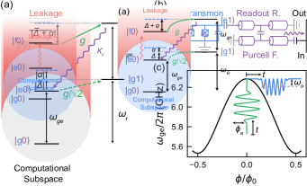
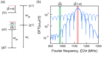
We realize the LRU by coupling the first leakage state of a flux-tunable transmon qubit, , to a readout resonator-Purcell filter system which is strongly coupled to a feed line acting as a dissipative environment, as illustrated with a simplified energy-level diagram in Fig. 1(a) and a full circuit diagram of the system in Fig. 1(b). For clarity, we consider a single readout mode in the energy-level diagram although we have two hybridized readout-resonator/Purcell-filter modes [44], see Appendix A for all relevant device parameters. We realize the coupling by applying a flux pulse with amplitude and modulation frequency to the flux line of the qubit [45, 46, 35], as depicted in Fig. 1(c) and detailed in Appendix B.
Because the qubit is operated at its upper flux-noise-insensitive bias point (i.e. with a DC flux bias of ), the flux modulation results in a qubit frequency modulation with leading-order sidebands at [39, 45, 46]. The amplitude of the qubit frequency modulation is denoted , and inferred in the experiments as described in Appendix C. When the high-frequency sideband [top dashed blue line in Fig. 1(a)] of is resonant with , population is transferred from to . Here the first state label corresponds to the state of the transmon qubit and the second to the Fock state of the resonator mode. This resonance condition is fulfilled when
| (1) |
where () is the transition frequency from to ( to ) at the bias point, is the transmon anharmonicity, and is the detuning between the qubit frequency and the transition frequency of the readout resonator mode. The overline symbol indicates the transition frequency from to time-averaged over the duration of the modulation pulse, i.e. and .
The resulting coupling strength depends on the modulation amplitude [39, 46]
| (2) |
with the coupling strength between the qubit and the readout resonator, and the first Bessel function of the first kind [47]. After the leaked population has been transferred to the readout resonator, the coupled system decays back to the computational state on the timescale of the effective decay rate of the resonator mode (Appendix A).
When the flux modulation pulse is tuned to satisfy the resonance condition of the LRU [Eq. 1], an analogous parametric transition from to with a coupling strength is detuned by only , as illustrated in Fig. 1(a). It is essential to suppress residual driving of this transition because it affects the computational subspace. To achieve this, we ensure that the bandwidth of the sideband is much smaller than by filtering the rising and falling edges of the flux pulse using a Gaussian kernel of width , see Appendix B. Furthermore, to suppress Purcell decay of the high-frequency sideband, we use a device architecture with an individual Purcell filter for each qubit and readout circuit parameters which ensure that the transmission through the readout resonator-Purcell filter system is suppressed at a detuning from resonance [48, 49].
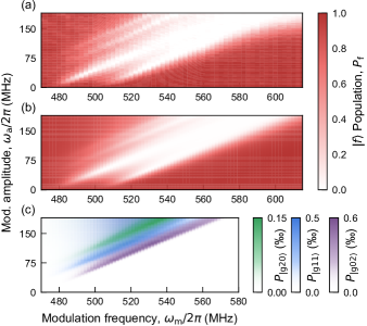
We first identify suitable operating points for the LRU, i.e. pairs of (, ) satisfying the resonance condition. Specifically, we prepare the qubit in , apply a flux modulation pulse with a fixed duration of , and subsequently measure the transmon qubit with three-state readout [33]. We sweep the modulation frequency and the modulation amplitude and identify four resonances yielding low population after , see the four slanted spectral lines in Fig. 2(a). The high-modulation-frequency resonance doublet corresponds to the parametric transition from to from the qubit into either one of the two resonator-Purcell-filter modes. We use the highest-frequency resonance of this doublet to implement the LRU. The two lower-frequency resonances are induced by a second-harmonic process, see Appendix D for details. For each of the spectral lines, the modulation frequency required to reach resonance increases linearly as a function of the modulation amplitude with a slope of approximately as the mean qubit frequency is shifted by during flux modulation, see also Eq. 1.
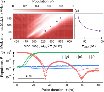
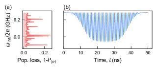
In a second calibration step, we fix the modulation amplitude and frequency, and vary the duration of the pulse to extract the minimal duration of the pulse yielding the lowest population of . For the operating point [purple circle in Fig. 2(a)], the achieved parametric coupling is large with respect to , which results in under-damped oscillations [35] of the population with a first minimum of after a pulse duration of only ( when accounting for the rising- and falling-edge buffers as detailed in Appendix B), see Fig. 2(b). The exhaustive depletion of the population in , down to the single-shot readout accuracy of approximately , demonstrates the high effectiveness of the LRU. The population dynamics of all three transmon eigenstates are in good agreement with master-equation simulations [solid lines in Fig. 2(b)], see Appendix E for details.
To gain further insight into the relationship between the modulation amplitude and the duration of the LRU, we measure the time evolution of the transmon population for four modulation amplitudes [purple markers in Fig. 2(a)] and extract the corresponding . As expected from simulations, decreases approximately as in our parameter regime, see purple markers in Fig. 2(c).
Although leakage errors can significantly impede the performance of QEC protocols, they are infrequent, typically occurring at a rate of 0.1-1% per qubit per QEC cycle [6, 49, 50]. Consequently, in practice the LRU acts on a state within the computational subspace most of the time, and it is therefore imperative to minimize its effect on this subspace. We investigate the effect of the LRU on the -basis states of the computational subspace for the operating point by comparing a measurement when applying a flux-modulation pulse of duration (blue), and a waiting time of equivalent duration (gray), see Fig. 3(a). We proceed analogously using a measurement to evaluate the effect on the -basis states [Fig. 3(b)].
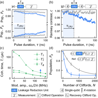
We observe only a small effect of the flux modulation pulse on short time scales (), with a population transfer from to of only in the measurement and a similar reduction in the contrast of Ramsey fringes in the measurement. These observations suggest that, as required, the modulated pulse leaves the computational subspace mostly unaffected on the time scale of the duration of an LRU operation.
We repeat the same measurements for longer time scales to accurately extract coherence times, and find an effective lifetime of () when the LRU is applied, compared to () when the LRU is not applied. We attribute this effective reduction in lifetime to population loss due to the repeated crossing of two-level defect modes [51, 52] in the frequency spectrum of the transmon when the modulation pulse is applied (Appendix F). The reduction in is ascribed to the decrease in as well as to the decrease in the pure dephasing time resulting from the qubit being away from its flux-noise-insensitive bias point during the modulation pulse.
We repeat these two characterization measurements for different operating points of the LRU and extract the effective coherence times , and when applying the modulation pulse as a function of the modulation amplitude, see Fig. 3(c). For all operating points, we observe that , which indicates that errors on the computational subspace are mostly -limited.
To extract the average error of the LRU on the computational subspace, we perform interleaved randomized benchmarking (iRB) [53] in which the LRU is benchmarked against a perfect identity operation. For the operating point [the coherence times of which are indicated by the blue arrow in Fig. 3(c)], we obtain an average gate error of 0.25(1)%, see Fig. 3(d). In comparison, the error for an idle operation of the same duration as the LRU is about 0.1%, showing that performing the LRU causes errors on the computational subspace of the same order of magnitude as coherence-limited single-qubit gates. The measured error is in good agreement with a calculated coherence limit [54] of 0.24% which takes into account the reduction in and during the LRU. We choose the operating point for all further experiments because it provides a good compromise between LRU duration and errors on the computational subspace.
To demonstrate the benefits of using an LRU in QEC experiments despite the small errors it causes on the computational subspace, we perform repeated cycles of a weight-two -type stabilizer measurement [49] with and without LRU, see Fig. 4(a) for the full quantum circuit diagram. The two data qubits (red dots) are initialized in one of the four -basis eigenstates and the parity of the state is mapped onto the auxiliary qubit (green dot) as shown in Fig. 4(a). An LRU can be applied to the auxiliary qubit, which is subsequently measured using single-shot three-level readout [49]. The entire stabilizer cycle of a fixed duration of is repeated times.
We find that when the LRU is applied, the accumulation of population in of the auxiliary qubit after 50 cycles, averaged over the four data-qubit input states, is reduced by approximately a factor of ten to [green dots in Fig. 4(b)], compared to when the LRU is not applied (gray dots). We observe a background residual leakage of about on average, even when we do not perform any stabilizer cycle, which is due to a frequency collision leading to state-dependent readout-induced leakage, see Appendix G. When considering solely the accumulation of leakage in addition to this background value, we calculate that the LRU leads to a 20-fold reduction in leakage accumulation. Moreover, we find that the application of the LRU to the auxiliary qubit also reduces leakage accumulation on data qubits, as shown in Fig. 4(c). We attribute this effect to a decrease in leakage transport [6, 7] which arises only when the auxiliary qubit is in . The differences in leakage between the two data qubits are currently not understood.
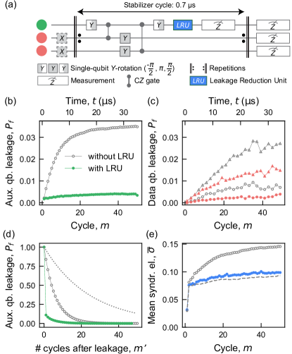
Furthermore, we extract the effective lifetime of a leakage event in the stabilizer circuit by post-selecting on runs in which leakage is detected on the auxiliary qubit and counting the average number of cycles in which the auxiliary qubit is consecutively read out in after the initial leakage event. We find that the LRU achieves the goal of reducing the leakage lifetime on the auxiliary qubit to close to a single cycle of the repeated stabilizer measurements, while the lifetime is on the order of 6 cycles when no LRU is used, see Fig. 4(d). In comparison, the -state lifetime of the auxiliary qubit in an independent measurement (dashed gray line) is much longer, approximately 24.6 cycles, which provides further evidence for leakage transport away from the auxiliary qubit during the repeated stabilizer measurement. From the reduction of the leakage lifetime, we infer that both space and time-correlated errors caused by leakage are suppressed [7].
To further investigate the impact of the LRU on the total number of detected errors by the stabilizer, we construct the error syndrome in each cycle from the current () and the previous () measured stabilizer values , with indicating an error and indicating no error, respectively [55, 49]. When averaging over all circuit runs and possible data-qubit input states, we find that applying the LRU reduces the mean error syndrome value from to after 50 cycles [Fig. 4(e)]. These results suggest that the LRU suppresses leakage-induced correlated errors and consequently reduces the total number of errors by approximately 33%. To further assess the performance of our approach, we compare the use of the LRU to a leakage-rejection method [dashed gray line in Fig. 4(e)] that discards experimental runs in which a leakage event on the auxiliary qubit is detected using three-level readout [49, 50]. Note that this method is not suited for large-scale QEC experiments because the amount of experimental runs left after leakage-rejection decreases exponentially with the number of QEC cycles and qubits. By contrast, employing the LRU results in nearly the same performance as the leakage rejection method, with the key benefit of scalability.
In summary, we have demonstrated a fast leakage reduction unit based on parametric flux modulation taking only , which effectively removes leakage down to our qubit readout error of . Moreover, it is high-fidelity, causing only an error of on the computational subspace. Our LRU thus approaches durations and fidelities comparable to those of single-qubit gates. We successfully integrated the LRU in a weight-two stabilizer measurement, thereby significantly improving its performance. Simulations show that the ability to suppress leakage will become even more relevant when executing large-scale quantum error correction circuits [7]. In the future, the presented LRU can also be applied to data qubits and thereby further reduce the total number of errors.
The LRU introduced in this work offers several advantages compared to other recent developments in leakage suppression [7, 37]. First, our LRU is four times faster than the one presented in Ref. 37, resulting in a reduction of idling errors on all qubits, which often constitute a substantial fraction of the total error budget [32, 56]. Second, the modulation pulses are generated by the same electronics which also generates pulses for the two-qubit gates, avoiding additional cost and complexity of the experimental setup. Finally, employing parametric coupling for realizing the LRU enables its use in a wide range of qubit-frequency configurations. Hence, this work showcases that the flux-activated parametric LRU is a promising approach to effectively suppress leakage in large-scale error correction circuits, which is an essential requirement for the practical implementation of fault-tolerant quantum computation.
Acknowledgments
The authors are grateful for valuable discussions with Markus Müller.
The team in Zurich acknowledges financial support by the Office of the Director of National Intelligence (ODNI), Intelligence Advanced Research Projects Activity (IARPA), via the U.S. Army Research Office grant W911NF-16-1-0071, by the EU Flagship on Quantum Technology H2020-FETFLAG-2018-03 project 820363 OpenSuperQ, by the National Centre of Competence in Research Quantum Science and Technology (NCCR QSIT), a research instrument of the Swiss National Science Foundation (SNSF), by the SNFS R’equip grant 206021-170731, by the EU program H2020-FETOPEN project 828826 Quromorphic and by ETH Zurich. S.K. acknowledges financial support from Fondation Jean-Jacques & Felicia Lopez-Loreta and the ETH Zurich Foundation. The work in Sherbrooke was undertaken thanks in part to funding from NSERC, Canada First Research Excellence Fund and ARO W911NF-18-1-0411, the Ministère de l’Économie et de l’Innovation du Québec, and U.S. Department of Energy, Office of Science, National Quantum Information Science Research Centers, Quantum Systems Accelerator. M.M. acknowledges support by the U.S. Army Research Office grant W911NF-16-1-0070. The views and conclusions contained herein are those of the authors and should not be interpreted as necessarily representing the official policies or endorsements, either expressed or implied, of the ODNI, IARPA, or the U.S. Government.
Competing interests
The authors declare no competing interests.
Data availability
All data is available from the corresponding authors upon reasonable request.
Appendix A Device and Experimental Setup
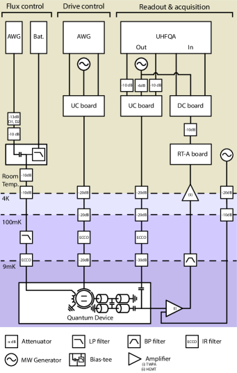
The experiments discussed in this manuscript were conducted on a subset of three qubits of a 17-qubit device similar to the one presented in Ref. 49, see Tab. 1 for qubit parameters, coherence properties and error rates. The LRU is implemented on an auxiliary qubit A, and two neighboring data qubits D1 and D2 are used to test the integration of the LRU in repeated weight-two stabilizer measurements. The device is mounted at the base plate of a dilution refrigerator [57] and connected to room-temperature control-electronics as summarized in Fig. 5.
To realize the LRU and two-qubit gates, voltage pulses generated by an AWG at a sampling rate of 2.4 GSa/s are applied to a dedicated flux line for each qubit [49]. The pulses induce a magnetic flux in the SQUID-loop of the corresponding target qubit which controls its transition frequency. The pulses are predistorted to compensate for the frequency response of the flux line. Note that the flux line of the auxiliary qubit has 13 dB less attenuation at the output of the AWG compared to the flux lines of the data qubits, to allow for the characterization of the LRU at large modulation amplitudes (). A DC current controlling the idle frequency of the qubit is combined with the voltage pulses using a bias-tee.
To implement single-qubit gates, an AWG generates DRAG drive pulses [19] at an intermediate frequency, which are then up-converted (UC) to microwave frequencies.
We generate readout pulses using the signal-generation unit of an ultra-high frequency quantum analyzer (UHFQA). The pulses are up-converted to microwave frequencies and applied to the readout input port of the device. The transmitted signal at the output port of the device is amplified by a wideband near-quantum-limited traveling-wave parametric amplifier (TWPA) [58], a high-electron-mobility transistor (HEMT) amplifier, and low-noise amplifiers operating at room-temperature (RT-A board) [49]. Subsequently, the amplified signal is down-converted with an IQ-mixer in a down-conversion (DC) board, and then both demodulated and integrated using the FPGA-based acquisition unit of the UHFQA.
| Parameter | D1 | A | D2 |
| Qubit idle frequency, (GHz) | 5.041 | 6.281 | 4.999 |
| Qubit anharmonicity, (MHz) | -167 | -154 | -167 |
| Lifetime, () | 29 | 21 | 64 |
| Ramsey decay time, () | 39 | 34 | 79 |
| Echo decay time, () | 51 | 35 | 99 |
| Readout frequency, (GHz) | 6.816 | 7.129 | 6.667 |
| Qb. freq. during RO, (GHz) | 5.054 | 6.281 | 5.572 |
| Dispersive shift, (MHz) | -3.9 | -5.0 | -4.0 |
| RO Resonator linewidth, (MHz) | 6.3 | 16.4 | 8.2 |
| Purcell filter linewidth, (MHz) | 26.5 | 35 | 27.6 |
| Purcell filter frequency, (GHz) | 6.855 | 7.111 | 6.689 |
| Qubit-RO res. coupling, (MHz) | 175 | 120 | 167 |
| RO res.- Purcell f. coupling, (MHz) | 22.0 | 28.8 | 22.2 |
| Two-state readout error, (%) | 0.56 | 0.54 | 0.52 |
| Three-state readout error, (%) | 1.29 | 1.53 | 1.53 |
| Two-qubit gate error, (%) | 0.82 0.73 | ||
| A-D1 gate leakage rate, (%) | 0.01 | 0.03 | n/a |
| A-D2 gate leakage rate, (%) | n/a | 0.03 | 0.00 |
Appendix B LRU Pulse Parameters
When the LRU is enabled, which occurs when the modulation frequency is chosen such that the high-frequency sideband of is resonant with , the transition between and is detuned by the anharmonicity , as illustrated by the energy-level diagram in Fig. 6(a). To suppress the off-resonant drive of this undesired transition which affects the computational subspace, we filter the flux pulse by convolving the square-shaped modulation pulse with a Gaussian kernel (characterized by its width ). This filtering process reduces the bandwidth of the sidebands, see Fig. 6(b) for a comparison between the spectrum of the first-order sideband of for (solid blue line) and without filtering, i.e. (dashed blue line). Consequently, the undesired overlap between the sideband and [green shaded area in Fig. 6(b)], is suppressed by several orders of magnitude compared to when no filtering is applied.
The resulting voltage pulse applied to the input of the flux line is given by
| (3) |
where is the voltage amplitude of the pulse, is the duration of the start and end buffer, is the Gaussian error function, is the duration of the square-shaped modulation pulse and is the time.
The pulse duration required to reach the first minimum in population [see Fig. 2(c) in the main text for an example], denoted as , increases with due to the impact of on the shape of the rising and falling edges of the pulse. Indeed, a larger reduces the effective duration at which the modulation amplitude is maximal. Furthermore, to avoid significant clipping of the waveform, the rising- and falling-edge buffers are adapted such that , which also results in a longer total LRU duration for larger .
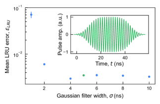
To investigate the tradeoff between LRU duration and Gaussian filter kernel width, we use interleaved randomized benchmarking (as described in the main text) and compare LRUs for different values of at the LRU operating point . We find that the LRU error is high for very small because the bandwidth of the qubit frequency modulation starts to overlap with the to transition, see Fig. 7. For , the error saturates around , which we mostly attribute to decoherence during the LRU and interactions with two-level defects (Appendix F). We choose and to ensure negligible driving of undesired transitions, but maintaining a fast LRU. Note that the LRU benchmarked in this measurement showed slightly worse performance than the one presented in the main text.
Appendix C Determination of the modulation amplitude
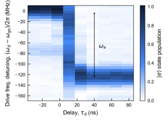
To accurately determine the modulation amplitude at the operating point , we measure the population of the auxiliary qubit A after applying a -pulse during a 1-µs-long modulated flux pulse with . Because the qubit is excited only when the drive tone is resonant with the qubit frequency, sweeping the frequency of the -pulse, , as well as its relative timing to the flux pulse, , allows to determine the qubit frequency during the flux pulse [59]. Note that the time-resolution of this method is limited by the duration of the drive pulse which has a Gaussian envelope with a width of . Consequently, the fast oscillation of the qubit frequency resulting from the flux modulation [ at the operating point ] cannot be resolved. Rather, this approach provides a good estimate of the average qubit frequency over the time window of the duration of the drive pulse. We extract the modulation amplitude by comparing the frequency which excites the qubit well before the flux pulse () i.e. the idle frequency, and the frequency which excites the qubit after the rising edge of the flux pulse (), and find a mean qubit frequency during modulation which yields for the operating point , see Fig. 8.
Because of the frequency-dependent attenuation of the flux line, performing explicit measurements of the modulation amplitude , as described above, for a two-dimensional sweep of the flux pulse modulation frequency and amplitude would be a tedious endeavor. To gain a qualitative understanding of the modulation amplitude dependence on the modulation frequency, as presented in Fig. 2(b), we therefore use a simpler yet less accurate approach. Specifically, we calculate the modulation amplitude based on the expected flux amplitude at the SQUID loop, taking into account the frequency response of the flux line and the non-linear qubit-frequency dependence on flux [black line in Fig. 1(c)]. Using this method, we obtain an estimate of the modulation amplitude of for the operating point , i.e. within of the value extracted using the precise characterization measurement described above. Subsequently, we adjust all modulation amplitude estimates in the landscape of Fig. 2(b) by rescaling them linearly based on the calibration point derived from the precise measurement of the modulation amplitude at the operating point .
Appendix D Other Parametric Resonances
We observe four main resonances which deplete the population of the transmon qubit for the modulation frequencies and modulation amplitudes swept in Fig. 2(a) of the main text, also reproduced in Fig. 9(a) for comparison to the master-equation simulations presented in Fig. 9(b). The two right-most resonances correspond to parametric transitions from to and , where the first state label describes the transmon state and the second and third denote the Fock state occupation numbers of the lower- and higher-frequency mode of the hybridized Purcell filter/readout resonator system, respectively. The mode hybridization arises in the parameter regime of our readout architecture [44], in which and . Here, represents the coupling strength between the readout resonator and the Purcell filter, denotes the linewidth of the Purcell filter, and is the detuning between the Purcell filter and the bare readout resonator frequency. The two resonances in Fig. 9(a) are separated in flux modulation frequency by about , or in qubit frequency due to the qubit being modulated at its upper flux-noise-insensitive bias point, which is in good agreement with the expected splitting of the hybridized modes of about and master-equation simulations of the full system, see Fig. 9(b). While either of the two modes can be used to realize the LRU, we choose the mode with the highest frequency [right-most slanted line in Fig. 9(a)] as it is further detuned from the closest parametric transition affecting the computational subspace, i.e. the transition from to .
We observe two additional resonances at lower modulation frequencies in Fig. 9(a), which we attribute to transitions from to , and from to driven via their second harmonic. Indeed, master-equation simulations confirm that and are residually populated after the 100-ns-long LRU for similar combinations of (, ), as indicated by the green and blue slanted lines in Fig. 9(c), respectively. The transition from to [the population of which is shown in purple shades in Fig. 9(c)] is only barely visible in the experimental data as it is close to the frequency of the transition from to . While these transitions could in principle also be used to realize the LRU, they would result in a considerably longer LRU duration for a fixed modulation amplitude, because the parametric coupling achieved using the second harmonic is weaker than the one obtained using the first harmonic [46]. In addition, the modulation frequencies enabling these transitions are closer to the modulation frequency enabling the undesired transitions from to or .
Appendix E Master Equation Simulations
In this Appendix, we provide a concise description of the numerical master-equation simulations employed to support the analysis of the experiment. The system consists of a transmon with charge and phase operators and respectively. It has a charging energy and a flux-tunable Josephson energy where is the external flux. The transmon is coupled to the readout resonator whose annihilation operator is with a bare frequency . The readout resonator itself is coupled to a Purcell filter with frequency and mode annihilation operator . The time-dependent Hamiltonian thus takes the form
| (4) |
Here, is the coupling between the transmon’s charge operator and the readout resonator, and is the coupling between Purcell filter and readout resonator respectively. Note that although one could safely make the rotating-wave approximation to the Hamiltonian Eq. 4 eliminating terms like , we include them in the numerical simulations. Furthermore, we keep six transmon eigenstates and 6 photons in both the resonator and filter modes.
To model dissipation, we assume that there is only dissipation on the (bare) Purcell filter mode. The master equation to be simulated is then
| (5) |
where is the bare dissipation rate. Note that here we have written the master equation in the bare basis: the decay rate in the main text thus corresponds to the Purcell decay rate which stems from the strong hybridization of the bare resonator and filter modes.
Since the couplings and dress the transmon, resonator and filter, it is crucial in the simulations that we make the distinction between the bare and dressed modes. The time-dependent-flux further complicates this picture. Therefore, we split the transmon Hamiltonian into two parts, namely the time-independent and time-dependent part of the Hamiltonian [38]
| (6) |
where is the standard transmon Hamiltonian and
| (7) |
with GHz the Josephson energy at the upper first-order insensitive flux bias point and the junction asymmetry [60]. Note that this picture is slightly different than that presented in the main text, where for instance in Eq. 2 is implicitly defined in the rotating frame of the instantaneous Hamiltonian. However, both frames coincide during initialization and measurements where the time-dependent external fluxes are set to zero, and thus the dressed eigenstates in both pictures are the same.
With this separation, we can now define the dressed modes, which constitute the eigenstates of the Hamiltonian Eq. (4) in the absence of flux drive (i.e ). We let denote the product state in the bare basis where labels the -th eigenstate of the transmon and , index the Fock states of resonator and Purcell filter respectively. We then denote the dressed basis by their tilded counterparts . Note that due the dispersive regime considered here, we can safely identify which eigenstates are mostly transmon-like. Since population measurements do not discriminate between how many photons are in the readout resonator or Purcell filter modes, we must trace over all such states. Thus, for instance, when we plot the population in the ground state numerically we are computing
| (8) |
where the sum over and performs a trace over the bosonic modes.
With the Hamiltonian Eq. 4, master equation Eq. 5 and state-identification procedure presented above, one can reproduce the plots in Fig. 2 assuming one is given the functional form of the external flux . The flux will be proportional to the applied voltage [Eq. 3],
| (9) |
where takes into account the constant of proportionality between the applied voltage and corresponding flux. To get the value of , we diagonalize the time dependent Hamiltonian Eq. 4 to obtain the instantaneous (dressed) qubit frequency by analogy to Fig. 8. The numerical value of is chosen to reproduce the experimental modulation depth MHz at the operating point , that is , where and are the maximum qubit transition frequency and the average value of the instantaneous qubit frequency , respectively. The Hamiltonian parameters of Eq. 4 are obtained from a simultaneous fit of the qubit transition frequency as a function of flux, the readout resonator-Purcell filter spectroscopy as a function of flux, and the residual population of the transmon at the first minimum and first maximum of the time evolution of the system [see Fig. 2(b)]. Using this procedure results in parameters which yield a time evolution well-describing the experimental data presented in Fig. 2(b). The calculated parameters are in reasonable agreement with independent spectroscopic measurements.
Appendix F Effect of the LRU on the Computational Subspace
During the modulated flux pulse, the qubit frequency rapidly oscillates between the idle frequency and , which increases the possibility of interacting with weakly coupled two-level defects in this frequency interval. We characterize the defect mode spectrum using an independent measurement in which we tune the qubit frequency to for after a -pulse, as described in Ref. [49], and show the resulting population loss in Fig. 10(a). We find that the calculated instantaneous qubit frequency during the LRU at the operating point [Fig. 10(b)] repeatedly crosses several weakly coupled defects during the operation of the LRU, and hypothesize that the reduction in lifetime of the state described in the main text primarily arises from the interaction with these defects.
The modulation of the qubit transition frequency also induces a coherent phase rotation of the qubit, which we counteract by applying a virtual -gate of equal magnitude and opposite sign. Note that applying this phase correction is not required when the LRU is applied to auxiliary qubits in stabilizer measurements, because the auxiliary qubits are in eigenstates of the -basis when the LRU is applied. Conversely, the phase correction is necessary when the LRU is applied to data qubits or used in a randomized benchmarking sequence.
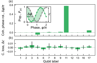
In addition to characterizing the impact of the flux modulation pulse on the computational subspace of the targeted qubit, it is crucial to evaluate its impact on the computational subspace of other qubits. Flux crosstalk may induce frequency deviations of neighboring qubits, leading to coherent phase rotation and/or dephasing. To investigate this effect, we repeat the phase-sensitive measurement described in the main text, but measure the phase of neighboring qubits instead of qubit whose flux is modulated. For each qubit A, we compare the phase with and without applying the flux pulse on qubit A to extract the coherent phase rotation induced by the pulse and the loss of contrast of the Ramsey fringes , see Fig. 11. We apply a flux modulation pulse at the operating point described in the main text with a duration of (i.e. approximately 30 times longer than the duration of the LRU at the operating point ) to amplify the resulting errors.
Our results indicate that for a 1-µs-long modulated flux pulse at the operating point , all measured qubits, except qubit D2, experience a coherent phase rotation of , see Fig. 11(a). This corresponds to , i.e. , for the duration of a single LRU operation. We also find that the contrast loss is close or equal to zero within error bars [Fig. 11(b)] for all measured qubits, indicating that the dephasing of neighboring qubits caused by flux crosstalk is negligible. These findings suggest that the impact of flux crosstalk is generally small.
We attribute the larger phase rotation on qubit D2, for the duration of an LRU operation, to the larger flux crosstalk between qubit A and qubit D2. Indeed, the cross-flux ratio [49] for D2, but is on the order of -3 or smaller for all other qubits. Here, is the sensitivity of the flux generated at the SQUID loop of qubit when varying the voltage applied to the flux line of qubit A, see Ref. [49] for details. When integrating the LRU in surface code experiments, we intend to correct crosstalk-induced coherent phase rotations by utilizing virtual- rotations of equal magnitude and opposite sign. However, we did not employ this approach in the repeated stabilizer measurement presented in the main text since qubit D2 remains in the eigenstate of the -basis throughout the execution of the quantum circuit.
Appendix G State-dependent Readout-induced Leakage
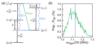
The residual leakage in the stabilizer measurement is higher than the level population of achievable with the LRU in an isolated setting, see Fig. 2(c). We believe the dominant factor limiting the residual population is a readout-induced two-qubit transition from to , where the first and second state labels denote the state of the auxiliary and data qubit, respectively. This transition has been used in prior work [61] to perform two-qubit gates by applying a tone corresponding to the frequency detuning between these two states to the drive line of one of the qubits. However, because the readout resonator is strongly coupled to the qubit, this transition can also be activated by a drive tone applied to the readout line. In our configuration, the readout frequency of qubit A coincides with the ac-Stark shifted transition frequency from to during the readout. Specifically, the readout frequency of qubit A is and the transition frequency during the readout varies between and for qubit A & D1 and and for qubit A & D2 due to the ac-Stark shift. An energy-level diagram of the two-qubit system illustrates the drive of the transition through virtual states [see Fig. 12(a)].
To observe the transition from to in an independent measurement, we prepare the system in , apply the readout tones to both qubits and infer the population after the readout. We reduce the readout amplitude and hence the ac-Stark shift of the auxiliary qubit compared to the other experiments presented in this work so that the ac-Stark shifted transition frequency is above the readout tone of the auxiliary qubit . To maintain high single-shot readout fidelity on the auxiliary qubit, we increase the duration of the readout tone from to . We sweep the transition-frequency of the data qubit during the readout using a flat-top flux pulse, thus sweeping through the readout frequency of the auxiliary qubit. We observe an increased transition probability as becomes resonant with the fixed-frequency readout-tone of the auxiliary qubit [Fig. 12(b)], indicating a drive of the two-qubit transition through the readout-tone and confirming state-dependent leakage induced by the readout tone of the auxiliary qubit.
In the stabilizer measurement, the described transition induces leakage of the auxiliary qubit if the auxiliary and data qubit are in the state before readout. The worst-case scenario occurs when both data qubits are in and the auxiliary qubit is in at the end of the stabilizer cycle because both readout-induced transitions are driven. This results in a residual leakage population of about 0.37(2)% for the auxiliary qubit after a single stabilizer cycle. Conversely, when both data qubits are in the ground state at the end of the cycle, neither of the readout-induced leakage transitions occur. In this case, we measure a leakage population of only about 0.04(5)% for the auxiliary qubit, which is consistent with the value of of shown in Fig. 2(c).
We note that the observed state-dependent readout induced leakage is specific to the frequency configuration of data qubits, auxiliary qubits and readout resonators on our device. Hence, this source of leakage can be avoided in future experiments by adjusting the design frequencies.
References
- Gottesman [2010] D. Gottesman, An introduction to quantum error correction and fault-tolerant quantum computation, in Proceedings of Symposia in Applied Mathematics, edited by S. J. Lomonaco, Jr. (2010).
- Terhal [2015] B. M. Terhal, Quantum error correction for quantum memories, Reviews of Modern Physics 87, 307 (2015).
- Preskill [2018] J. Preskill, Quantum Computing in the NISQ era and beyond, Quantum 2, 79 (2018).
- Knill et al. [1998] E. Knill, R. Laflamme, and W. H. Zurek, Resilient quantum computation: error models and thresholds, Proceedings of the Royal Society of London. Series A: Mathematical, Physical and Engineering Sciences 454, 365 (1998).
- Aharonov and Ben-Or [1999] D. Aharonov and M. Ben-Or, Fault-Tolerant Quantum Computation With Constant Error Rate, arXiv 10.48550/arXiv.quant-ph/9906129 (1999), quant-ph/9906129 .
- McEwen et al. [2021] M. McEwen, D. Kafri, Z. Chen, J. Atalaya, K. J. Satzinger, C. Quintana, P. V. Klimov, D. Sank, C. Gidney, A. G. Fowler, F. Arute, K. Arya, B. Buckley, B. Burkett, N. Bushnell, B. Chiaro, R. Collins, S. Demura, A. Dunsworth, C. Erickson, B. Foxen, M. Giustina, T. Huang, S. Hong, E. Jeffrey, S. Kim, K. Kechedzhi, F. Kostritsa, P. Laptev, A. Megrant, X. Mi, J. Mutus, O. Naaman, M. Neeley, C. Neill, M. Niu, A. Paler, N. Redd, P. Roushan, T. C. White, J. Yao, P. Yeh, A. Zalcman, Y. Chen, V. N. Smelyanskiy, J. M. Martinis, H. Neven, J. Kelly, A. N. Korotkov, A. G. Petukhov, and R. Barends, Removing leakage-induced correlated errors in superconducting quantum error correction, Nature Communications 12, 1 (2021).
- Miao et al. [2022] K. C. Miao, M. McEwen, J. Atalaya, D. Kafri, L. P. Pryadko, A. Bengtsson, A. Opremcak, K. J. Satzinger, Z. Chen, P. V. Klimov, C. Quintana, R. Acharya, K. Anderson, M. Ansmann, F. Arute, K. Arya, A. Asfaw, J. C. Bardin, A. Bourassa, J. Bovaird, L. Brill, B. B. Buckley, D. A. Buell, T. Burger, B. Burkett, N. Bushnell, J. Campero, B. Chiaro, R. Collins, P. Conner, A. L. Crook, B. Curtin, D. M. Debroy, S. Demura, A. Dunsworth, C. Erickson, R. Fatemi, V. S. Ferreira, L. F. Burgos, E. Forati, A. G. Fowler, B. Foxen, G. Garcia, W. Giang, C. Gidney, M. Giustina, R. Gosula, A. G. Dau, J. A. Gross, M. C. Hamilton, S. D. Harrington, P. Heu, J. Hilton, M. R. Hoffmann, S. Hong, T. Huang, A. Huff, J. Iveland, E. Jeffrey, Z. Jiang, C. Jones, J. Kelly, S. Kim, F. Kostritsa, J. M. Kreikebaum, D. Landhuis, P. Laptev, L. Laws, K. Lee, B. J. Lester, A. T. Lill, W. Liu, A. Locharla, E. Lucero, S. Martin, A. Megrant, X. Mi, S. Montazeri, A. Morvan, O. Naaman, M. Neeley, C. Neill, A. Nersisyan, M. Newman, J. H. Ng, A. Nguyen, M. Nguyen, R. Potter, C. Rocque, P. Roushan, K. Sankaragomathi, C. Schuster, M. J. Shearn, A. Shorter, N. Shutty, V. Shvarts, J. Skruzny, W. C. Smith, G. Sterling, M. Szalay, D. Thor, A. Torres, T. White, B. W. K. Woo, Z. J. Yao, P. Yeh, J. Yoo, G. Young, A. Zalcman, N. Zhu, N. Zobrist, H. Neven, V. Smelyanskiy, A. Petukhov, A. N. Korotkov, D. Sank, and Y. Chen, Overcoming leakage in scalable quantum error correction, arxiv 10.48550/ARXIV.2211.04728 (2022).
- Aliferis and Terhal [2007] P. Aliferis and B. M. Terhal, Fault-tolerant quantum computation for local leakage faults, Quantum Info. Comput. 7, 139 (2007).
- Fowler [2013] A. G. Fowler, Coping with qubit leakage in topological codes, Phys. Rev. A 88, 042308 (2013).
- Ghosh and Fowler [2015] J. Ghosh and A. G. Fowler, Leakage-resilient approach to fault-tolerant quantum computing with superconducting elements, Physical Review A 91, 020302 (2015).
- Suchara et al. [2015] M. Suchara, A. W. Cross, and J. M. Gambetta, Quantum Info. Comput. 15, 997 (2015).
- Bultink et al. [2020] C. C. Bultink, T. E. O’Brien, R. Vollmer, N. Muthusubramanian, M. W. Beekman, M. A. Rol, X. Fu, B. Tarasinski, V. Ostroukh, B. Varbanov, A. Bruno, and L. DiCarlo, Protecting quantum entanglement from leakage and qubit errors via repetitive parity measurements, Science Advances 6, eaay3050 (2020).
- Varbanov et al. [2020] B. M. Varbanov, F. Battistel, B. M. Tarasinski, V. P. Ostroukh, T. E. O’Brien, L. DiCarlo, and B. M. Terhal, Leakage detection for a transmon-based surface code, npj Quantum Information 6, 102 (2020).
- Battistel et al. [2021] F. Battistel, B. Varbanov, and B. Terhal, Hardware-efficient leakage-reduction scheme for quantum error correction with superconducting transmon qubits, PRX Quantum 2, 030314 (2021).
- Stricker et al. [2020] R. Stricker, D. Vodola, A. Erhard, L. Postler, M. Meth, M. Ringbauer, P. Schindler, T. Monz, M. Müller, and R. Blatt, Experimental deterministic correction of qubit loss, Nature 585, 207 (2020).
- Hayes et al. [2020] D. Hayes, D. Stack, B. Bjork, A. C. Potter, C. H. Baldwin, and R. P. Stutz, Eliminating Leakage Errors in Hyperfine Qubits, Physical Review Letters 124, 170501 (2020).
- Andrews et al. [2019] R. W. Andrews, C. Jones, M. D. Reed, A. M. Jones, S. D. Ha, M. P. Jura, J. Kerckhoff, M. Levendorf, S. Meenehan, S. T. Merkel, A. Smith, B. Sun, A. J. Weinstein, M. T. Rakher, T. D. Ladd, and M. G. Borselli, Quantifying error and leakage in an encoded si/sige triple-dot qubit, Nature Nanotechnology 14, 747 (2019).
- Wu et al. [2022] C. Wu, S. Kumar, Y. Kan, D. Komisar, Z. Wang, S. I. Bozhevolnyi, and F. Ding, Room-temperature on-chip orbital angular momentum single-photon sources, Science Advances 8, eabk3075 (2022), https://www.science.org/doi/pdf/10.1126/sciadv.abk3075 .
- Motzoi et al. [2009] F. Motzoi, J. M. Gambetta, P. Rebentrost, and F. K. Wilhelm, Simple pulses for elimination of leakage in weakly nonlinear qubits, Phys. Rev. Lett. 103, 110501 (2009).
- Chen et al. [2016] Z. Chen, J. Kelly, C. Quintana, R. Barends, B. Campbell, Y. Chen, B. Chiaro, A. Dunsworth, A. G. Fowler, E. Lucero, E. Jeffrey, A. Megrant, J. Mutus, M. Neeley, C. Neill, P. J. J. O’Malley, P. Roushan, D. Sank, A. Vainsencher, J. Wenner, T. C. White, A. N. Korotkov, and J. M. Martinis, Measuring and suppressing quantum state leakage in a superconducting qubit, Phys. Rev. Lett. 116, 020501 (2016).
- Werninghaus et al. [2021] M. Werninghaus, D. J. Egger, F. Roy, S. Machnes, F. K. Wilhelm, and S. Filipp, Leakage reduction in fast superconducting qubit gates via optimal control, npj Quantum Information 7, 14 (2021).
- Lazăr et al. [2022] S. Lazăr, Q. Ficheux, J. Herrmann, A. Remm, N. Lacroix, C. Hellings, F. Swiadek, D. C. Zanuz, G. J. Norris, M. B. Panah, A. Flasby, M. Kerschbaum, J. Besse, C. Eichler, and A. Wallraff, Calibration of drive non-linearity for arbitrary-angle single-qubit gates using error amplification, arXiv:2212.01077 (2022).
- Barends et al. [2016] R. Barends, A. Shabani, L. Lamata, J. Kelly, A. Mezzacapo, U. L. Heras, R. Babbush, A. G. Fowler, B. Campbell, Y. Chen, Z. Chen, B. Chiaro, A. Dunsworth, E. Jeffrey, E. Lucero, A. Megrant, J. Y. Mutus, M. Neeley, C. Neill, P. J. J. O’Malley, C. Quintana, P. Roushan, D. Sank, A. Vainsencher, J. Wenner, T. C. White, E. Solano, H. Neven, and J. M. Martinis, Digitized adiabatic quantum computing with a superconducting circuit, Nature 534, 222 (2016).
- Rol et al. [2019] M. A. Rol, F. Battistel, F. K. Malinowski, C. C. Bultink, B. M. Tarasinski, R. Vollmer, N. Haider, N. Muthusubramanian, A. Bruno, B. M. Terhal, and L. DiCarlo, Fast, high-fidelity conditional-phase gate exploiting leakage interference in weakly anharmonic superconducting qubits, Phys. Rev. Lett. 123, 120502 (2019).
- Collodo et al. [2020] M. C. Collodo, J. Herrmann, N. Lacroix, C. K. Andersen, A. Remm, S. Lazar, J.-C. Besse, T. Walter, A. Wallraff, and C. Eichler, Implementation of conditional phase gates based on tunable interactions, Phys. Rev. Lett. 125, 240502 (2020).
- Negirneac et al. [2021] V. Negirneac, H. Ali, N. Muthusubramanian, F. Battistel, R. Sagastizabal, M. S. Moreira, J. F. Marques, W. J. Vlothuizen, M. Beekman, C. Zachariadis, N. Haider, A. Bruno, and L. DiCarlo, High-fidelity controlled- gate with maximal intermediate leakage operating at the speed limit in a superconducting quantum processor, Phys. Rev. Lett. 126, 220502 (2021).
- Sank et al. [2016] D. Sank, Z. Chen, M. Khezri, J. Kelly, R. Barends, B. Campbell, Y. Chen, B. Chiaro, A. Dunsworth, A. Fowler, and et al., Measurement-induced state transitions in a superconducting qubit: Beyond the rotating wave approximation, Physical Review Letters 117, 190503 (2016).
- Shillito et al. [2022] R. Shillito, A. Petrescu, J. Cohen, J. Beall, M. Hauru, M. Ganahl, A. G. Lewis, G. Vidal, and A. Blais, Dynamics of transmon ionization, Phys. Rev. Applied 18, 034031 (2022).
- Khezri et al. [2022] M. Khezri, A. Opremcak, Z. Chen, A. Bengtsson, T. White, O. Naaman, R. Acharya, K. Anderson, M. Ansmann, F. Arute, K. Arya, A. Asfaw, J. C. Bardin, A. Bourassa, J. Bovaird, L. Brill, B. B. Buckley, D. A. Buell, T. Burger, B. Burkett, N. Bushnell, J. Campero, B. Chiaro, R. Collins, A. L. Crook, B. Curtin, S. Demura, A. Dunsworth, C. Erickson, R. Fatemi, V. S. Ferreira, L. F. Burgos, E. Forati, B. Foxen, G. Garcia, W. Giang, M. Giustina, R. Gosula, A. G. Dau, M. C. Hamilton, S. D. Harrington, P. Heu, J. Hilton, M. R. Hoffmann, S. Hong, T. Huang, A. Huff, J. Iveland, E. Jeffrey, J. Kelly, S. Kim, P. V. Klimov, F. Kostritsa, J. M. Kreikebaum, D. Landhuis, P. Laptev, L. Laws, K. Lee, B. J. Lester, A. T. Lill, W. Liu, A. Locharla, E. Lucero, S. Martin, M. McEwen, A. Megrant, X. Mi, K. C. Miao, S. Montazeri, A. Morvan, M. Neeley, C. Neill, A. Nersisyan, J. H. Ng, A. Nguyen, M. Nguyen, R. Potter, C. Quintana, C. Rocque, P. Roushan, K. Sankaragomathi, K. J. Satzinger, C. Schuster, M. J. Shearn, A. Shorter, V. Shvarts, J. Skruzny, W. C. Smith, G. Sterling, M. Szalay, D. Thor, A. Torres, B. W. K. Woo, Z. J. Yao, P. Yeh, J. Yoo, G. Young, N. Zhu, N. Zobrist, D. Sank, A. Korotkov, Y. Chen, and V. Smelyanskiy, Measurement-induced state transitions in a superconducting qubit: Within the rotating wave approximation 10.48550/ARXIV.2212.05097 (2022).
- Thorbeck and Abdo [2021] T. Thorbeck and B. Abdo, Electrical circuits for leakage reduction units (2021), US Patent 11183989B1, Holder: International Business Machines.
- Ahonen et al. [2022] O. Ahonen, J. Heinsoo, P. Lähteenmäki, M. Möttönen, J. Rönkkö, J. Salo, J. Santos, and J. Tuorila, Qubit leakage error reductions (2022), US Patent 2022006458A1, Holder: IQM Finland Oy.
- Chen et al. [2021] Z. Chen, K. J. Satzinger, J. Atalaya, A. N. Korotkov, A. Dunsworth, D. Sank, C. Quintana, M. McEwen, R. Barends, P. V. Klimov, S. Hong, C. Jones, A. Petukhov, D. Kafri, S. Demura, B. Burkett, C. Gidney, A. G. Fowler, A. Paler, H. Putterman, I. Aleiner, F. Arute, K. Arya, R. Babbush, J. C. Bardin, A. Bengtsson, A. Bourassa, M. Broughton, B. B. Buckley, D. A. Buell, N. Bushnell, B. Chiaro, R. Collins, W. Courtney, A. R. Derk, D. Eppens, C. Erickson, E. Farhi, B. Foxen, M. Giustina, A. Greene, J. A. Gross, M. P. Harrigan, S. D. Harrington, J. Hilton, A. Ho, T. Huang, W. J. Huggins, L. B. Ioffe, S. V. Isakov, E. Jeffrey, Z. Jiang, K. Kechedzhi, S. Kim, A. Kitaev, F. Kostritsa, D. Landhuis, P. Laptev, E. Lucero, O. Martin, J. R. McClean, T. McCourt, X. Mi, K. C. Miao, M. Mohseni, S. Montazeri, W. Mruczkiewicz, J. Mutus, O. Naaman, M. Neeley, C. Neill, M. Newman, M. Y. Niu, T. E. O’Brien, A. Opremcak, E. Ostby, B. Pató, N. Redd, P. Roushan, N. C. Rubin, V. Shvarts, D. Strain, M. Szalay, M. D. Trevithick, B. Villalonga, T. White, Z. J. Yao, P. Yeh, J. Yoo, A. Zalcman, H. Neven, S. Boixo, V. Smelyanskiy, Y. Chen, A. Megrant, J. Kelly, and A. I. Google Quantum, Exponential suppression of bit or phase errors with cyclic error correction, Nature 595, 383 (2021).
- Magnard et al. [2018] P. Magnard, P. Kurpiers, B. Royer, T. Walter, J.-C. Besse, S. Gasparinetti, M. Pechal, J. Heinsoo, S. Storz, A. Blais, and A. Wallraff, Fast and unconditional all-microwave reset of a superconducting qubit, Phys. Rev. Lett. 121, 060502 (2018).
- Egger et al. [2018] D. Egger, M. Werninghaus, M. Ganzhorn, G. Salis, A. Fuhrer, P. Müller, and S. Filipp, Pulsed reset protocol for fixed-frequency superconducting qubits, Phys. Rev. Applied 10, 044030 (2018).
- Zhou et al. [2021] Y. Zhou, Z. Zhang, Z. Yin, S. Huai, X. Gu, X. Xu, J. Allcock, F. Liu, G. Xi, Q. Yu, H. Zhang, M. Zhang, H. Li, X. Song, Z. Wang, D. Zheng, S. An, Y. Zheng, and S. Zhang, Rapid and unconditional parametric reset protocol for tunable superconducting qubits, Nature Communications 12, 5924 (2021).
- Fowler et al. [2012] A. G. Fowler, M. Mariantoni, J. M. Martinis, and A. N. Cleland, Surface codes: Towards practical large-scale quantum computation, Phys. Rev. A 86, 032324 (2012).
- Marques et al. [2023] J. F. Marques, H. Ali, B. M. Varbanov, M. Finkel, H. M. Veen, S. L. M. van der Meer, S. Valles-Sanclemente, N. Muthusubramanian, M. Beekman, N. Haider, B. M. Terhal, and L. DiCarlo, All-microwave leakage reduction units for quantum error correction with superconducting transmon qubits, Phys. Rev. Lett. 130, 250602 (2023).
- Koch et al. [2007] J. Koch, T. M. Yu, J. Gambetta, A. A. Houck, D. I. Schuster, J. Majer, A. Blais, M. H. Devoret, S. M. Girvin, and R. J. Schoelkopf, Charge-insensitive qubit design derived from the Cooper pair box, Phys. Rev. A 76, 042319 (2007).
- Beaudoin et al. [2012] F. Beaudoin, M. P. da Silva, Z. Dutton, and A. Blais, First-order sidebands in circuit qed using qubit frequency modulation, arXiv:1208.1946v1 (2012).
- Andersen et al. [2020] C. K. Andersen, A. Kamal, N. A. Masluk, I. M. Pop, A. Blais, and M. H. Devoret, Quantum versus classical switching dynamics of driven dissipative kerr resonators, Phys. Rev. Applied 13, 044017 (2020).
- Marques et al. [2021] J. F. Marques, B. M. Varbanov, M. S. Moreira, H. Ali, N. Muthusubramanian, C. Zachariadis, F. Battistel, M. Beekman, N. Haider, W. Vlothuizen, A. Bruno, B. M. Terhal, and L. DiCarlo, Logical-qubit operations in an error-detecting surface code, Nature Physics 10.1038/s41567-021-01423-9 (2021).
- Wu et al. [2021] Y. Wu, W. Bao, S. Cao, F. Chen, M. Chen, X. Chen, T. Chung, H. Deng, Y. Du, D. Fan, M. Gong, C. Guo, C. Guo, S. Guo, L. Han, L. Hong, H. Huang, Y. Huo, L. Li, N. Li, S. Li, Y. Li, F. Liang, C. Lin, J. Lin, H. Qian, D. Qiao, H. Rong, H. Su, L. Sun, L. Wang, S. Wang, D. Wu, Y. Xu, K. Yan, W. Yang, Y. Yang, Y. Ye, J. Yin, C. Ying, J. Yu, C. Zha, C. Zhang, H. Zhang, K. Zhang, Y. Zhang, H. Zhao, Y. Zhao, L. Zhou, Q. Zhu, C. Lu, C. Peng, X. Zhu, and J. Pan, Strong quantum computational advantage using a superconducting quantum processor, Physical Review Letters (2021).
- Cohen et al. [2023] J. Cohen, A. Petrescu, R. Shillito, and A. Blais, Reminiscence of classical chaos in driven transmons, PRX Quantum 4, 020312 (2023).
- Swiadek et al. [2023] F. Swiadek, R. Shillito, P. Magnard, A. Remm, C. Hellings, N. Lacroix, Q. Ficheux, D. C. Zanuz, G. J. Norris, A. Blais, S. Krinner, and A. Wallraff, Enhancing dispersive readout of superconducting qubits through dynamic control of the dispersive shift: Experiment and theory, arXiv:2307.07765 (2023).
- Strand et al. [2013] J. D. Strand, M. Ware, F. Beaudoin, T. A. Ohki, B. R. Johnson, A. Blais, and B. L. T. Plourde, First-order sideband transitions with flux-driven asymmetric transmon qubits, Phys. Rev. B 87, 220505 (2013).
- Caldwell et al. [2018] S. A. Caldwell, N. Didier, C. A. Ryan, E. A. Sete, A. Hudson, P. Karalekas, R. Manenti, M. P. da Silva, R. Sinclair, E. Acala, N. Alidoust, J. Angeles, A. Bestwick, M. Block, B. Bloom, A. Bradley, C. Bui, L. Capelluto, R. Chilcott, J. Cordova, G. Crossman, M. Curtis, S. Deshpande, T. E. Bouayadi, D. Girshovich, S. Hong, K. Kuang, M. Lenihan, T. Manning, A. Marchenkov, J. Marshall, R. Maydra, Y. Mohan, W. O’Brien, C. Osborn, J. Otterbach, A. Papageorge, J.-P. Paquette, M. Pelstring, A. Polloreno, G. Prawiroatmodjo, V. Rawat, M. Reagor, R. Renzas, N. Rubin, D. Russell, M. Rust, D. Scarabelli, M. Scheer, M. Selvanayagam, R. Smith, A. Staley, M. Suska, N. Tezak, D. C. Thompson, T.-W. To, M. Vahidpour, N. Vodrahalli, T. Whyland, K. Yadav, W. Zeng, and C. Rigetti, Parametrically activated entangling gates using transmon qubits, Phys. Rev. Applied 10, 034050 (2018).
- Watson [1995] G. N. Watson, A Treatise on the Theory of Bessel Functions (Cambridge University Press, Cambridge, England, UK, 1995).
- Heinsoo et al. [2018] J. Heinsoo, C. K. Andersen, A. Remm, S. Krinner, T. Walter, Y. Salathé, S. Gasparinetti, J.-C. Besse, A. Potočnik, A. Wallraff, and C. Eichler, Rapid high-fidelity multiplexed readout of superconducting qubits, Phys. Rev. Appl. 10, 034040 (2018).
- Krinner et al. [2022] S. Krinner, N. Lacroix, A. Remm, A. D. Paolo, E. Genois, C. Leroux, C. Hellings, S. Lazar, F. Swiadek, J. Herrmann, G. J. Norris, C. K. Andersen, M. Müller, A. Blais, C. Eichler, and A. Wallraff, Realizing repeated quantum error correction in a distance-three surface code, Nature 605, 669 (2022).
- Sundaresan et al. [2023] N. Sundaresan, T. J. Yoder, Y. Kim, M. Li, E. H. Chen, G. Harper, T. Thorbeck, A. W. Cross, A. D. Córcoles, and M. Takita, Demonstrating multi-round subsystem quantum error correction using matching and maximum likelihood decoders, Nature Communications 14, 1 (2023).
- Klimov et al. [2018] P. V. Klimov, J. Kelly, Z. Chen, M. Neeley, A. Megrant, B. Burkett, R. Barends, K. Arya, B. Chiaro, Y. Chen, A. Dunsworth, A. Fowler, B. Foxen, C. Gidney, M. Giustina, R. Graff, T. Huang, E. Jeffrey, E. Lucero, J. Y. Mutus, O. Naaman, C. Neill, C. Quintana, P. Roushan, D. Sank, A. Vainsencher, J. Wenner, T. C. White, S. Boixo, R. Babbush, V. N. Smelyanskiy, H. Neven, and J. M. Martinis, Fluctuations of energy-relaxation times in superconducting qubits, Phys. Rev. Lett. 121, 090502 (2018).
- Lisenfeld et al. [2019] J. Lisenfeld, A. Bilmes, A. Megrant, R. Barends, J. Kelly, P. Klimov, G. Weiss, J. M. Martinis, and A. V. Ustinov, Electric field spectroscopy of material defects in transmon qubits, npj Quantum Information 5, 10.1038/s41534-019-0224-1 (2019).
- Magesan et al. [2012] E. Magesan, J. M. Gambetta, B. R. Johnson, C. A. Ryan, J. M. Chow, S. T. Merkel, M. P. da Silva, G. A. Keefe, M. B. Rothwell, T. A. Ohki, M. B. Ketchen, and M. Steffen, Efficient measurement of quantum gate error by interleaved randomized benchmarking, Phys. Rev. Lett. 109, 080505 (2012).
- Assad et al. [2016] S. M. Assad, O. Thearle, and P. K. Lam, Maximizing device-independent randomness from a bell experiment by optimizing the measurement settings, Phys. Rev. A 94, 012304 (2016).
- Kelly et al. [2015] J. Kelly, R. Barends, A. G. Fowler, A. Megrant, E. Jeffrey, T. C. White, D. Sank, J. Y. Mutus, B. Campbell, Y. Chen, Z. Chen, B. Chiaro, A. Dunsworth, I.-C. Hoi, C. Neill, P. J. J. O’Malley, C. Quintana, P. Roushan, A. Vainsencher, J. Wenner, A. N. Cleland, and J. M. Martinis, State preservation by repetitive error detection in a superconducting quantum circuit, Nature 519, 66 (2015).
- Google Quantum AI [2023] Google Quantum AI, Suppressing quantum errors by scaling a surface code logical qubit, Nature 614, 676 (2023).
- Krinner et al. [2019] S. Krinner, S. Storz, P. Kurpiers, P. Magnard, J. Heinsoo, R. Keller, J. Lütolf, C. Eichler, and A. Wallraff, Engineering cryogenic setups for 100-qubit scale superconducting circuit systems, EPJ Quantum Technology 6, 2 (2019).
- Macklin et al. [2015] C. Macklin, K. O’Brien, D. Hover, M. E. Schwartz, V. Bolkhovsky, X. Zhang, W. D. Oliver, and I. Siddiqi, A near-quantum-limited Josephson traveling-wave parametric amplifier, Science 350, 307 (2015).
- Hellings et al. [2023] C. Hellings et al., Manuscript in preparation, (2023).
- Blais et al. [2021] A. Blais, A. L. Grimsmo, S. M. Girvin, and A. Wallraff, Circuit quantum electrodynamics, Rev. Mod. Phys. 93, 025005 (2021).
- Krinner et al. [2020] S. Krinner, P. Kurpiers, B. Royer, P. Magnard, I. Tsitsilin, J.-C. Besse, A. Remm, A. Blais, and A. Wallraff, Demonstration of an all-microwave controlled-phase gate between far-detuned qubits, Phys. Rev. Appl. 14, 044039 (2020).