On the sign of the linear magnetoelectric coefficient in Cr2O3
Abstract
We establish the sign of the linear magnetoelectric coefficient, , in chromia, Cr2O3. Cr2O3 is the prototypical linear magnetoelectric material, in which an electric (magnetic) field induces a linearly proportional magnetization (polarization), and a single magnetic domain can be selected by annealing in combined magnetic () and electric () fields. Opposite antiferromagnetic domains have opposite magnetoelectric responses, and which antiferromagnetic domain corresponds to which sign of response has previously been unclear. We use density functional theory (DFT) to calculate the magnetic response of a single antiferromagnetic domain of Cr2O3 to an applied in-plane electric field at zero kelvin. We find that the domain with nearest neighbor magnetic moments oriented away from (towards) each other has a negative (positive) in-plane magnetoelectric coefficient, , at zero kelvin. We show that this sign is consistent with all other DFT calculations in the literature that specified the domain orientation, independent of the choice of DFT code or functional, the method used to apply the field, and whether the direct (magnetic field) or inverse (electric field) magnetoelectric response was calculated. Next, we reanalyze our previously published spherical neutron polarimetry data to determine the antiferromagnetic domain produced by annealing in combined and fields oriented along the crystallographic symmetry axis at room temperature. We find that the antiferromagnetic domain with nearest-neighbor magnetic moments oriented away from (towards) each other is produced by annealing in (anti-)parallel and fields, corresponding to a positive (negative) axial magnetoelectric coefficient, , at room temperature. Since at zero kelvin and at room temperature are known to be of opposite sign, our computational and experimental results are consistent.
I Introduction
Materials in which both time-reversal and space-inversion symmetries are broken, while the product symmetry is preserved, have a term in their free energy of the form
| (1) |
where / are electric / magnetic fields, is the nine-component magnetoelectric tensor (SI units ) and is the unit cell volume. This term reveals two distinctive and related material properties. First, there is a preferred magnetic domain orientation, determined by the sign and form of , in simultaneous magnetic and electric fields, so that annealing in such a combination of fields, called magnetoelectric annealing, can be used to select for a specific magnetic domain. Second, by differentiating Eq. 1 with respect to electric (magnetic) field to obtain the polarization (magnetization), we see that
| (2) |
and
| (3) |
where is the vacuum permeability. Eqs. 2 and 3 reveal a linear proportionality between an applied electric (magnetic) field and an induced magnetization (polarization ), with the response tensor.
Materials with non-zero therefore show a linear magnetoelectric (ME) effect and are promising for spintronic applications since they enable voltage-control of magnetism Borisov2008 .

Corundum-structure chromia, , is the prototypical linear magnetoelectric, and the first material in which the linear ME effect was predicted Dzyaloshinskii:1960 and measured Astrov:1960 ; Astrov1961 . In addition to its historical relevance, has a high Néel temperature compared to other ME materials, and continues to be the primary material of focus in theoretical, experimental and technological studies of the ME effect. We show the primitive rhombohedral unit cell of in Fig. 1(a). Below its Néel temperature = 307 K Brockhouse1953 , adopts a superexchange-mediated easy-axis antiferromagnetic (AFM) “up-down-up-down” ordering of the magnetic dipole moments on the ions along the rhombohedral direction Dudko1971 ; Tobia2010 . The magnetic space group breaks both and while preserving , thus allowing a linear ME response Fechner2018 . In Fig. 1 (b) we show the primitive unit cell of the opposite AFM domain, with “down-up-down-up” magnetic dipole ordering. While (a) and (b) are energetically degenerate in the absence of external fields, they correspond to opposite ME domains. As a result, the signs of their linear ME responses are opposite, and they are obtained by ME annealing in opposite combinations of and fields. In Fig. 1(c), we show the unit cell of in the hexagonal setting conventionally used in neutron diffraction, in which the hexagonal axis is parallel to the rhombohedral axis.
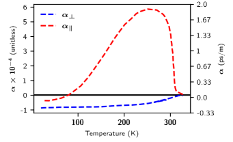
The symmetry of the magnetic space group allows for a diagonal response tensor , described by two independent components which we denote as and Dzyaloshinskii:1960 :
| (4) |
describes the magnetization (polarization) induced when () is applied along the rhombohedral axis, and refers to the perpendicular ME response when the field and induced property lie in the basal plane. Fig. 2 shows the measured temperature dependence of and , extracted from the original experimental report Astrov1961 . While , which results from the -field induced canting of the magnetic dipole moments away from the easy axis Iniguez:2008 ; blMalashevich2012 , follows the usual order-parameter onset below , has a peak in magnitude just below before decreasing and switching sign at low temperature. This is understood in terms of the response of spin fluctuations at high temperature Mostovoy_et_al:2010 , with the orbital magnetization response blMalashevich2012 dominating at low temperature. Importantly, at =0 K, relevant to first-principles calculations, and have the same sign, whereas at room temperature, relevant to many experimental setups, and have opposite signs.
While the relative signs of and were established unambiguously in Ref. Astrov:1960 , it was not possible at the time to determine which set of values correspond to the out-pointing or in-pointing magnetic domains of Figs. 1 a) and b). Instead, Ref. Astrov:1960 showed that reversal of the AFM domain reverses the signs of as required by symmetry, and that the measured magnitudes in multi-domain or poly-crystalline samples are substantially reduced due to cancellation effects.
The experimental determination of the specific bulk AFM domain corresponding to a particular ME response is highly non-trivial and requires a generalized form of polarized neutron scattering called spherical neutron polarimetry; to our knowledge only four such experiment has been performed for Cr2O3 Brown/Forsyth/Tasset:1998 ; Brown/Forsyth/Tasset:1999 ; Brown_et_al:2002 . While in principle first-principles calculations based on density functional theory (DFT) yield this information directly, the AFM domain modeled is often not reported in the literature, and the sensitivity of the magnetic anisotropy to the details of the DFT parameters render an independent experimental determination desirable. To compound confusion, in both the theoretical and experimental literature the terms “magnetic moments” and “spins” have sometimes been used interchangeably, in spite of their being opposite in sign.
The purpose of this paper is to establish unambiguously the signs of the ME effect corresponding to each of the two opposite AFM domains in Cr2O3. We achieve this goal by reviewing and reanalyzing the relevant computational and experimental literature, as well as presenting the results of our own new DFT calculations. In Sec. II, we begin by reviewing the DFT-based results for the zero-kelvin values of and , computed both by us and by others in earlier publications. We then perform a comprehensive cross-check of the domain-dependent sign of using four different codes, three different methods for applying the external fields, and different choices of DFT parameters.
We find that the ab-initio results give consistent signs for across authors, DFT parameters, and codes used.
In Sec. III, we reanalyze the seminal neutron polarimetry experiments which provided the first experimental indicator for the sign of Forsyth_1988 ; Brown/Forsyth/Tasset:1998 ; Brown/Forsyth/Tasset:1999 ; Brown_et_al:2002 . While the stated conclusion of the original polarimetry papers contradicts the DFT findings, we show that this is actually due to the assumed sample orientation with respect to the instrument axes during analysis in Refs. Forsyth_1988 ; Brown/Forsyth/Tasset:1999 ; Brown_et_al:2002 . When we account for and correct these inconsistencies, the raw polarimetry data indicate a room-temperature sign of for a given AFM domain consistent with all DFT calculations (taking into account the experimental temperature dependence of found by Astrov in Fig. 2). We hope that this paper clears up long-standing ambiguities and confusions in the literature, and facilitates future interpretations of theoretical and experimental data related to the ME effect in and other ME materials.
II Computational studies
Several ab initio studies of the magnitude and sign of the ME effect in Cr2O3 have been performed previously blMalashevich2012 ; Iniguez:2008 ; Ye/Vanderbilt:2014 ; Bousquet/Spaldin/Delaney:2011 ; Mostovoy_et_al:2010 . Three main techniques have been employed: Explicit inclusion of i) a static magnetic field or ii) a static electric field within the DFT Hamiltonian, and iii) the so-called “lattice-mediated” method, in which a polar displacement of the ions simulates the application of an electric field. Both spin and orbital contributions to the response have been calculated, and has been resolved into so-called clamped-ion (the electronic response to an electric field with fixed ions) and lattice-mediated (in which the ions are displaced by the electric field) components. Since most DFT codes (in particular abinit Gonze:2020 ; Romero:2020 , elk ELK , quantum espresso Gianozzi_et_al:2009 ; Giannozzi_et_al:2017 and vasp Kresse/Furthmueller_CMS:1996 ; Kresse/Furthmueller_PRB:1996 ) output magnetic moments rather than spins, we adopt this convention here.
| Source | Code | PP | XC | U (eV) | SOC | Unit cell | Contributions | Method | ps/m | g.u. | ps/m | g.u. |
| to | () | () | ||||||||||
| Ref. blMalashevich2012 | QE | NC | PBE | no U | yes | PBE | LM+CI, S+O | electric field | ||||
| Ref. Iniguez:2008 | VASP | PAW | LDA | U | yes | expt. | LM, S | lattice-mediated | ||||
| Ref. Ye/Vanderbilt:2014 | QE | NC | PBE | no U | yes | PBE | LM, S+O | lattice-mediated | ||||
| Ref. Bousquet/Spaldin/Delaney:2011 | VASP | PAW | LDA | U | yes | expt. | LM+CI,S | Zeeman field | ||||
| Ref. Mostovoy_et_al:2010 ∗ | VASP | PAW | LDA | U | no | expt. | LM+CI, S | magnetic | ||||
| exchange | ||||||||||||
| This work | ELK | AE | LDA | U = 4.0 | yes | LDA | LM, S | lattice-mediated | ||||
| J = 0.5 | ||||||||||||
| This work | VASP | PAW | LDA | U = 4.0 | yes | LDA | LM, S | lattice-mediated | ||||
| J = 0.5 | ||||||||||||
| This work | QE | US | PBE | no U | yes | PBE | LM, S | lattice-mediated | ||||
| This work | Abinit | NC | LDA | no U | yes | expt. | LM+CI, S | Zeeman field | ||||
| This work | Abinit | NC | LDA | no U | yes | expt. | LM+CI, S | electric field | ||||
∗ Results obtained at K.
First, we summarize the results of the various literature studies that report both the AFM domain studied and the sign of the calculated . The technical details for each calculation are summarized in Table 1. First, Malashevich et al. blMalashevich2012 found and to have the same positive sign at 0 K for a domain with in-pointing moments. [as in Fig. 1(b)]. They used the finite electric-field method so that both spin and orbital contributions and the full lattice-mediated and electronic responses were included. For the same domain, Íñiguez Iniguez:2008 used the ’lattice-mediated’ method and obtained a positive 0 K lattice-mediated spin ME response ; since Ref. Iniguez:2008 did not include orbital contributions, was zero. Also using the lattice-mediated approach but including the orbital contributions, Ye and Vanderbilt Ye/Vanderbilt:2014 found positive and for the domain with in-pointing moments at 0 K. Bousquet et al. Bousquet/Spaldin/Delaney:2011 , using an explicitly applied magnetic Zeeman field, including both the lattice-mediated and clamped-ion spin contributions, find a positive 0 K for the in-pointing domain as well PriComm_delayney_2023 . Finally, Mostovoy et al. Mostovoy_et_al:2010 considered the opposite domain (note that Fig. 1 of Ref. Mostovoy_et_al:2010 shows spins) and calculated the finite-temperature spin contribution to , using Monte-Carlo simulations of a DFT-derived model Hamiltonian containing Heisenberg exchanges and a magnetic moment - polarization coupling. They found a positive in the temperature range of = 60-400 K, consistent with a negative at = 0 K [Fig. 2]. Since their calculations modeled the out-pointing domain, these results are consistent with the other computational studies discussed earlier.
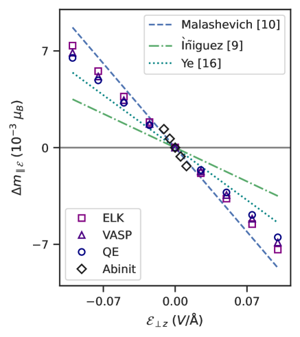
To supplement the literature results, we perform a comprehensive cross-check of the domain-dependent sign of using four different codes and three different methods. First, we calculate the lattice-mediated spin contribution to using the lattice-mediated method, as described in Ref. Iniguez:2008 , using the elk ELK , vasp Kresse/Furthmueller_CMS:1996 ; Kresse/Furthmueller_PRB:1996 , and quantum espresso Gianozzi_et_al:2009 ; Giannozzi_et_al:2017 codes, with the parameters listed in Table 1. In all cases we find for the out-pointing domain at 0 K, consistent with the literature findings summarized above. In addition, we use the abinit code Gonze:2020 ; Romero:2020 to calculate the spin contribution to the ME effect by both explicitly applying an electric field as in Ref. blMalashevich2012 , and a magnetic Zeeman field method as in Ref. Bousquet/Spaldin/Delaney:2011 . Both methods give the same positive value of for the in-pointing domain at 0 K. Computational details for the calculations in elk, vasp, quantum espresso, and abinit can be found in Appendices A-D. We list our calculated values in Table 1, and in Fig. 3, we plot the induced in-plane magnetizations as a function of in-plane electric fields calculated here and from the literature. Although there is complete agreement on the sign of , it is clear that there is some spread in the magnitude of calculated values. This distribution cannot be explained only by the different contributions to that were taken into account, and is most likely also the result of the different choices in electronic structure code, electronic exchange parameters and convergence criteria. Considering these differences, the agreement on the magnitude of is remarkable.
In summary, the calculated signs of are consistent across DFT codes and methodologies, with the 0 K and positive for the in-pointing domain, the 0 K negative for the out-pointing domain, and the room temperature positive for the out-pointing domain. We summarize this result in Tab. 2 with the addition values at 0 K and room T extrapolated.
| 0 K | |||
| out-pointing domain | |||
| in-pointing domain | |||
| RT | |||
| out-pointing domain | |||
| in-pointing domain |
III Experimental studies
To our knowledge, there exist four sets of data in which the magnetic structure of Cr2O3 was measured using spherical neutron polarimetry (SNP), the generalized form of polarized neutron scattering Forsyth_1988 ; Brown/Forsyth/Tasset:1998 ; Brown/Forsyth/Tasset:1999 ; Brown_et_al:2002 . This technique allows for both the detection of the domain imbalance between the two different magnetic structures shown in Fig. 1, and for the determination of the magnetic moment configuration of the predominant domain Brown/Forsyth/Tasset:1998 . This is possible because with SNP, the polarization vectors of both the incident and scattered neutron beams are determined; in comparison, in conventional (uniaxial) polarized neutron scattering, the scattered neutron polarization information is only analyzed along the direction of the incident beam polarization LelievreBerna:2007tm . Therefore, SNP is an ideal method for elucidating which spin configuration shown in Fig. 1 is stabilized by the parallel or anti-parallel combination of electric and magnetic fields.
The SNP measurements reported in Refs. Forsyth_1988 ; Brown/Forsyth/Tasset:1998 ; Brown/Forsyth/Tasset:1999 ; Brown_et_al:2002 were performed at the IN20 and D3 beamlines at the Institut Laue Langevin (ILL, Grenoble), using the CRYOgenic Polarization Analysis Device (Cyopad). The Cryopad consists of a zero-magnetic field sample chamber surrounded by magnetic fields manipulating the incident (Pi) and scattered (Pf) beam polarizations Tasset:1999wp ; LelievreBerna:2005vj . The field regions are decoupled with a pair of concentric superconducting Meissner shields combined with µ-metal yokes and screens. The incident neutron beam polarization was controlled using a combination of a nutator and precession coil, and was oriented along one of three orthogonal experimental co-ordinates which were defined as , which is along the direction of the scattering vector Q, , which is perpendicular to the horizontal scattering plane, and , which completes the right-handed co-ordinate set. The polarization of the scattered neutron beam was also analyzed along these three principal axes using another set of precession and nutator coils.
In each of the four studies, the Cr2O3 sample was aligned so that the crystal -axis was perpendicular to the horizontal scattering plane, which allowed access to the reflections (importantly, this introduces an ambiguity between and , which we will discuss in more detail in the following section). Here, the Miller indices correspond to the hexagonal setting of the rhombohedral () unit cell of Cr2O3 adopted in Refs. Forsyth_1988 ; Brown/Forsyth/Tasset:1998 ; Brown/Forsyth/Tasset:1999 ; Brown_et_al:2002 . In the three most recent studies, prior to installing the sample in the Cryopad for the SNP measurements, the Cr2O3 sample was cooled through the Néel temperature (310 K) in a combination of electric and magnetic fields oriented along the crystallographic axis to achieve an imbalance of 180∘ domain population Brown/Forsyth/Tasset:1998 ; Brown/Forsyth/Tasset:1999 ; Brown_et_al:2002 . Brown et al. reported that this annealing process stabilized a single AFM domain Brown/Forsyth/Tasset:1998 ; Brown/Forsyth/Tasset:1999 ; Brown_et_al:2002 , and that the type of AFM domain (Fig. 1) could be chosen based on the relative orientation of the external magnetic (H) and electric fields (E). The experimental determination of which magnetic domain is favoured then boils down to the determination and interpretation of the sign of the polarization matrix element .
Experimentally, is determined by measuring two quantities, namely and , which are the number of scattered neutrons with the polarization parallel and antiparallel to for the incident neutron polarization along . The experimental matrix element is in turn obtained by taking the ratio,
| (5) |
for a given Bragg reflection Q = . As such, the quantity is bounded between -1 and 1.
In order to determine which AFM domain is favoured, the authors in Refs. Brown/Forsyth/Tasset:1999 ; Brown_et_al:2002 ; Brown/Forsyth/Tasset:1998 ; Forsyth_1988 expressed in terms of three dimensionless quantities,
| (6) |
The term defines the population imbalance between the two magnetic domains, and is given by = , where and are the volumes of the two magnetic domains. Hence, the value of is bounded between 1 and -1. If the two magnetic domains are equally populated, the factor becomes 0. The term is determined by the orientation of the crystal with respect to the experimental set up, with the sign of depending on whether the crystallographic axis is along the or direction of the experimental geometry; for example is +1 (-1) if the magnetic interaction vector is parallel (anti-parallel) to the axis of the experimental geometry. Hence, it is crucial to determine whether is along the or direction. Finally, the term is associated with the magnetic structure, with the sign of being positive (negative) for the out-pointing (in-pointing) magnetic domain.
Based on this discussion, we identify three inconsistencies across the four Refs. Forsyth_1988 ; Brown/Forsyth/Tasset:1998 ; Brown/Forsyth/Tasset:1999 ; Brown_et_al:2002 , which we clarify here. (Note that the measurements in Refs. Forsyth_1988 ; Brown/Forsyth/Tasset:1998 ; Brown/Forsyth/Tasset:1999 ; Brown_et_al:2002 were made with the same crystal by the same group of coauthors so we expect the underlying physics to be consistent).
III.1 Spin vs magnetic moment
The first discrepancy is between Ref. Brown_et_al:2002 and Ref. Brown/Forsyth/Tasset:1998 , regarding the definition of spin and magnetic moments. In Ref. Brown_et_al:2002 , the authors propose that the antiparallel E and H fields favor the ‘out-pointing’ arrows [Fig. 1(a)] and designate the arrows as spin directions. On the other hand in Ref. Brown/Forsyth/Tasset:1998 , the authors present ‘in-pointing’ arrows [Fig. 1(b)], which they designate as magnetic moments, and state that this magnetic structure is stabilized by parallel E and H fields. Since the Cr spin direction and magnetic moment direction are anti-parallel, these two statements are incompatible.
In the neutron scattering community, however, the terms spin and magnetic moment are often used interchangeably to mean magnetic moment direction. We should therefore assume that the arrows in Ref. Brown_et_al:2002 actually indicate magnetic moments, rather than spins as stated. This resolves the apparent discrepancy between Ref. Brown/Forsyth/Tasset:1998 and Ref. Brown_et_al:2002 .
III.2 Orientation of the crystal b axis
Second, the labelling of the Miller indices across the four reports is inconsistent. In the first report Forsyth_1988 , the two reported reflections, namely and , are in fact forbidden by the space group in the hexagonal setting of Cr2O3. In the subsequent study, the two reported reflections, and are both allowed by . In the following two reports Brown/Forsyth/Tasset:1999 ; Brown_et_al:2002 , where forty reflections were reported in total, thirty-two are in fact forbidden by the space group of Cr2O3. The and Miller indices of the remaining eight reflections are both multiples of 3, e.g. and , and are hence allowed.
| Parallel H and E | ||||||||||||||||
| Crystal | Axis | Axis | Axis | out pointing | in pointing | |||||||||||
| I | 0.00 | 0.00 | 0.88 | 0.83 | 0.06 | 0.08 | 0.88 | 0.00 | 0.00 | -0.88 | 0.00 | 0.00 | ||||
| 0.00 | 0.00 | 0.72 | -0.69 | 0.06 | -0.06 | -0.72 | 0.00 | 0.00 | 0.72 | 0.00 | 0.00 | |||||
| 0.00 | 0.00 | 0.72 | -0.70 | 0.05 | -0.05 | -0.72 | 0.00 | 0.00 | 0.72 | 0.00 | 0.00 | |||||
| II | 0.88 | 0.00 | 0.00 | -0.10 | 0.00 | 0.86 | 0.00 | 0.00 | 0.88 | 0.00 | 0.00 | -0.88 | ||||
| 0.00 | 0.88 | 0.00 | 0.06 | 0.88 | 0.03 | 0.00 | 0.88 | 0.00 | 0.00 | 0.88 | 0.00 | |||||
| 0.00 | 0.00 | 0.88 | -0.87 | 0.03 | 0.02 | -0.88 | 0.00 | 0.00 | 0.88 | 0.00 | 0.00 | |||||
| Anti-parallel H and E | ||||||||||||||||
| Crystal | Axis | Axis | Axis | out pointing | in pointing | |||||||||||
| I | 0.00 | 0.00 | 0.72 | 0.71 | 0.12 | 0.02 | -0.72 | 0.00 | 0.00 | 0.72 | 0.00 | 0.00 | ||||
| 0.00 | 0.00 | 0.72 | 0.70 | 0.16 | 0.05 | -0.72 | 0.00 | 0.00 | 0.72 | 0.00 | 0.00 | |||||
| II | 0.88 | 0.00 | 0.00 | 0.12 | 0.00 | -0.85 | 0.00 | 0.00 | 0.88 | 0.00 | 0.00 | -0.88 | ||||
| 0.00 | 0.88 | 0.00 | 0.00 | 0.88 | -0.05 | 0.00 | 0.88 | 0.00 | 0.00 | 0.88 | 0.00 | |||||
| 0.00 | 0.00 | 0.88 | 0.86 | 0.12 | 0.14 | -0.88 | 0.00 | 0.00 | 0.88 | 0.00 | 0.00 | |||||
| II | 0.88 | 0.00 | 0.00 | 0.10 | 0.06 | -0.86 | 0.00 | 0.00 | 0.88 | 0.00 | 0.00 | -0.88 | ||||
| 0.00 | 0.88 | 0.00 | -0.09 | 0.88 | 0.02 | 0.00 | 0.88 | 0.00 | 0.00 | 0.88 | 0.00 | |||||
| 0.00 | 0.00 | 0.88 | 0.87 | 0.03 | 0.08 | -0.88 | 0.00 | 0.00 | 0.88 | 0.00 | 0.00 | |||||
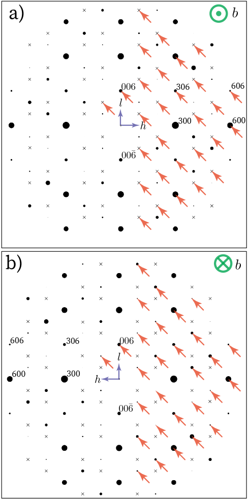
Given that the magnetic propagation vector of Cr2O3 is =, the magnetic scattering intensity occurs at the same reciprocal space location as the structural Bragg peaks of Cr2O3. As such, the Miller index of the magnetic/nuclear reflections should follow the general condition of the space group, where =. Since the four reports were concerned with reflections in the plane, the observed reflections should obey the rule =, given that =0. In figure 4(a) we plot the calculated reciprocal space maps for Cr2O3 in the scattering plane, assuming that the crystal axis is along the direction as stated in the original papers. Here, the allowed reflections, such as and , are denoted by the black filled circles, and the reciprocal space location of the forbidden reflections that do not obey = are shown by the crosses ().
The observed reflections in Refs. Forsyth_1988 ; Brown/Forsyth/Tasset:1999 ; Brown_et_al:2002 are denoted by the arrows in the reciprocal space map. Indeed, many of the observed reflections, including and , are in fact forbidden by the space group.
If instead, we assume that the crystal axis was oriented along the direction (rather than ), then the reciprocal space location of all forty-two observed reflections reported in Forsyth_1988 ; Brown/Forsyth/Tasset:1999 ; Brown_et_al:2002 , is fully compatible with the space group. This scenario is very plausible, due to a possible mix up between the and crystal axes, which are in-equivalent in Cr2O3. As shown in Fig. 4(b), where we plot the calculated reciprocal space maps for Cr2O3 in the scattering plane, assuming that the crystal axis is along the direction, the reciprocal space location of the observed reflections denoted by all of the arrows can now be accounted for.
Changing the direction of the axis has two main consequences for the interpretation of the results in Refs Forsyth_1988 ; Brown/Forsyth/Tasset:1999 ; Brown_et_al:2002 . First it swaps the Miller index of the reflections, such that the observed peaks which were designated as should be assigned as instead. This would allow the thirty-four reflection which are originally forbidden now be compatible with , i.e. to obey the = condition. The remaining eight reflections which have the and Miller indices both being multiples of 3, still obey this condition. The second is that in Ref Brown/Forsyth/Tasset:1998 the sign of changes, which means that the interpretation of which magnetic domain is favoured also changes.
Therefore, we conclude that the conjugate field with E and H parallel favours the ‘out-pointing’ domain, as shown in Fig. 1(a). By the same token, the antiparallel E and H field favours the ‘in-pointing’ domain. This is opposite to the interpretation in Ref. Brown_et_al:2002 .
III.3 Sign of
Finally, the third inconsistency is between Refs. Brown/Forsyth/Tasset:1999 and Brown_et_al:2002 . In these studies, the term was obtained by measuring the polarization component of various reflections. Ref. Brown/Forsyth/Tasset:1999 reports, in Table 3, the values for twelve reflections obtained on the IN20 instrument with thermal neutrons (=1.532 Å). On the other hand, Ref. Brown_et_al:2002 reports the measurements of for a further fifteen reflections acquired on the D3 instrument with hot neutrons. Table 2 of Ref. Brown_et_al:2002 lists the data acquired from the D3 instrument along with those measured on the IN20 instrument, which were reported in Brown/Forsyth/Tasset:1999 .
The discrepancy lies in the sign of of the data collected on the IN20 instrument, which are reported both in Table 2 of Ref. Brown_et_al:2002 and also in Table 3 of Ref. Brown/Forsyth/Tasset:1999 . Although the Miller indices of the twelve reflections and their corresponding magnitude of are the same, the signs are different. Since the sign of is used to interpret whether the magnetic domain is ‘out-pointing’ or ‘in-pointing’, this discrepancy calls into question which sign of was measured.
To resolve the ambiguity, here we use the Mag2Pol software Mag2pol to re-analyze the measured spherical neutron polarimetry data presented in Table 2 of Ref. Brown/Forsyth/Tasset:1998 . We choose this data set because the Miller indices are allowed by the space group, and the raw data are presented explicitly. Moreover, these measurements were performed on cooling the Cr2O3 sample with a conjugate field of parallel or anti-parallel E and H fields through to =290 K, where the measurements were performed. Tables 3 and 4 tabulate the measured polarization matrices for the case where E and H are parallel and anti-parallel, respectively, along with the results of our new analysis for the two cases where the magnetic domain is ‘out-pointing’ or ‘in-pointing’.
Our analysis assuming an ‘out-pointing’ domain is consistent with the measured scattered neutron polarization for the case where E and H are parallel, contrary to the conclusions in Refs. Forsyth_1988 ; Brown_et_al:2002 ; Brown/Forsyth/Tasset:1998 ; Brown/Forsyth/Tasset:1999 . Similarly, for the case where E and H are anti-parallel, we find that the measured polarization matrices are consistent with an ‘in-pointing’ domain.
IV Conclusion
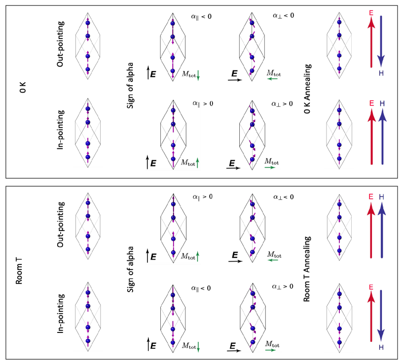
We have combined a literature review, new ab-initio results, and a careful reanalysis of spherical neutron polarimetry data in an effort to resolve long-standing confusion regarding the domain-dependent sign of the ME coefficient in . We have shown that all ab-initio results to date are in agreement in the assignments of negative and positive low-temperature to the out-pointing and in-pointing domains depicted in Fig. 1. These conclusions are remarkably consistent across multiple codes and methods. Gratifyingly, the room-temperature spherical neutron polarimetry data are consistent with the low-temperature ab-initio findings given that the room-temperature sign of is opposite to its low-temperature sign. The opposite interpretation in some of our literature experimental papers stems from a sign error due to subtle inconsistencies in the analysis which we discussed in Sec. III. The confusion and deceptive inconsistency have also been compounded in the past by ambiguous terminology from numerous authors related to the usage of “spin” versus “magnetic” moment. We summarize the relationship between the domains and the sign of , as well as the necessary alignment of the and fields during magnetoelectric annealing, in Fig. 5.
We mention here an important consequence of our work for a related feature of ; the magnitude and sign of the uncompensated magnetization on the surface for a given bulk domain He_et_al:2010 ; Borisov2016 . At the - limit in the absence of thermal fluctuations, the direction of the surface magnetization is unambiguously determined by the bulk domain which is selected in the ME annealing process. For example, with the in-pointing domain depicted for the hexagonal cell in Fig. 1(c), the surface magnetization from the dangling at the surface points outwards (positive). However, for any experimental characterizations performed at room-temperature, the relation between the bulk domain and the sign of surface magnetization is much less clear. Indeed, recent DFT-Monte Carlo calculations performed by some of the authors Weber2023 indicate that the surface magnetic moments of are essentially paramagnetic at room temperature due to weak coupling to the bulk order parameter. Thus, it is likely that for a fixed domain, the surface magnetization is substantially reduced, or even switches sign, with respect to its value. Now that we have definitively determined which domain is selected by a given ME annealing at room temperature, it will be very interesting to re-examine, and perform new, experimental measurements of surface magnetization to determine its sign for an unambiguous selection of bulk domain.
We hope that our work convincingly demonstrates the previously questioned consistency of computational and experimental findings on the sign of the ME coefficient in , and that it may motivate new, updated polarimetry measurements to test and confirm existing experimental and theoretical results. We also hope that this paper will assist in the correct interpretation of future studies of , as well as providing a cautionary tale for similar investigations of other ME materials.
V Acknowledgements
JRS, NAS, AU, XHV, and SFW were supported by the ERC under the European Union’s Horizon 2020 research and innovation programme grant No. 810451 and by the ETH Zürich. Computational resources for the elk and vasp calculations were provided by ETH Zürich’s Euler cluster, and by SISSA through its Linux Cluster and ITCS for the Quantum ESPRESSO calculations. EB acknowledges the FNRS for support and the computational resources provided by the Consortium des Équipements de Calcul Intensif (CÉCI, FNRS grant No. 2.5020.11) and the Tier-1 supercomputer of the Fédération Wallonie-Bruxelles funded by the Walloon Region (Grant No. 1117545). The authors thank Kris Delaney for providing us with the original input files for Ref. Bousquet/Spaldin/Delaney:2011 so that we could extract the magnetic domain used for the applied Zeeman field calculations. ELB and NQ would like to pay tribute to their friend F. Tasset, inventor of the Cryopad, who passed away earlier this year.
VI Data availability statement
All data that support the findings of this study are included within the article (and any supplementary files).
VII Author Contributions
XHV performed the calculations in elk and vasp, AU performed those in Quantum ESPRESSO and EB those in abinit. JRS, NQ and ELB performed the re-analysis of the SNP data. NAS conceived of and coordinated the project. All authors co-wrote the manuscript.
VIII Conflict of interest
The authors declare that there is no conflict of interest.
Appendix A Computational details ELK
Our DFT calculations in the augmented-plane wave (APW) code elk were performed with spin-orbit interaction included, using the non-collinear local spin density approximation (LSDA) Perdew/Zunger:1981 . Correlation effects were taken into account by applying a rotationally invariant Hubbard U correction Liechtenstein_U on the Cr states, with U eV and J eV, which well describe the physics of Cr2O3 shi:2009 ; mu:2014 ; Fechner2018 . Muffin-tin spheres were used to describe the Cr and O core states, with radii of 1.0716 Å and 0.80435 Å. These radii are reduced by 4% with respect to the standard setting to prevent overlap of the muffin-tin spheres. The APW functions and the potential were expanded in a spherical harmonics basis, with cut-offs . A -centered k-point mesh was used to sample the Brillouin Zone (BZ) Monkhorst/Pack:1976 . We obtained the spin contributions to the lattice-mediated ME response in the xy-plane using the lattice-mediated method of Ref. Iniguez:2008 , in which the response is constructed from a superposition of the magnetic moments induced by freezing in those eigenmodes of the force constant matrix that give a net polarization, in this case those with symmetry. We used LSDA + U relaxed lattice parameters and atomic positions obtained from vasp calculations (see the description below). Force constant matrix eigenmodes and their energies were obtained from vasp interfaced with phonopy phonopy ; phonopy-phono3py-JPSJ . Born effective charges, used to calculate the polarization, were taken from vasp calculations as well.
Appendix B Computational details VASP
In the plane-wave code vasp, we performed density functional theory calculations with the LSDA+U method, spin-orbit coupling included, and a Hubbard U correction on the Cr states, with U (J) = () eV, as in the elk calculations. The ionic cores of Cr and O were described with projector-augmented wave pseudopotentials Bloechl:1994 . We used the following settings for the valence electrons: Cr 3p63d54s1 and O 2s22p4, corresponding to the datasets Cr_sv and O. We used a kinetic energy cut-off of 800 eV for the wavefunctions and performed the BZ integrations using a uniform -centered k-point mesh. Structural and electronic relaxations performed with these parameters yielded a band gap and magnetic moment close to known experimental values and lattice parameters of , the length of the rhombohedral unit cell vectors and , the angle between the unit cell vectors. These values are 0.78% and 0.26% smaller than experiment Hill:2010 . As for the elk calculations, we used the method of Ref. Iniguez:2008 to construct the lattice-mediated spin response to an applied electric field, from the net spin magnetic moment induced by freezing in appropriate eigenmodes of the force constant matrix. The eigenmodes and corresponding energies were calculated by interfacing vasp with phonopy. The polarizations of each of the eigenmodes were obtained from the product of the atomic displacements of the mode and the Born effective charges . We computed the by displacing each atom in the unit cell along each Cartesian direction and determining the ionic polarization using the modern theory of polarization, as implemented in vasp in the LCALCPOL routine. These calculations were performed for four displacements of different magnitudes, allowing us to assess the linear response regime. The final were obtained from the average of the for different atoms of the same species and different displacements within the linear regime.
Appendix C Computational details Quantum Espresso
First-principles calculations in Quantum ESPRESSO Gianozzi_et_al:2009 ; Giannozzi_et_al:2017 and thermo_pw thermo_pw were performed in non-collinear DFT using the generalized gradient approximation, with the Perdew-Burke-Ernzerhof parametrization of the exchange-correlation energy Perdew/Burke/Ernzerhof:1996 . Ions were described by fully relativistic ultrasoft pseudopotentials (PPs) US_Vanderbilt , with 3, 3, 4, and 4 valence electrons for Cr (PP Cr.rel-pbe-spn-rrkjus_psl.0.2.3.UPF from pslibrary 1.0.0 pslibrary ; pslibrary_2 ) and with 2 and 2 valence electrons for O (PP O.rel-pbe-n-rrkjus_psl.0.1.UPF from pslibrary 0.1). The pseudo wavefunctions (charge density) were expanded in a plane-wave basis set with kinetic energy cut-off of 140 (560) Ry. BZ integrations were performed using a shifted k-points mesh of points. The lattice-mediated spin contribution to the ME response was computed following the approach of Ref. Iniguez:2008 : specifically, Born effective charges and phonon frequencies at were computed using density functional perturbation theory DFPT_review_Baroni .
Appendix D Computational details Abinit
The ABINIT calculations (version 8.8) were done with the norm-conserving pseudo-potentials coming from the PseudoDojo project pseudodojo (v0.3) and within the LDA approximation for the exchange correlation functional without Hubbard U correction. We used a kinetic energy cut-off of 40 Ha (1088 eV) for the plane-wave expansion and integrated the BZ using a Monkhorst-Pack -points mesh of points, shifted by (0.5, 0.5, 0,5). Spin-orbit coupling was included in all the calculations for both applied Zeeman field and applied electric field calculations. The cell parameters and shape were fixed to the experimental ones ( 5.37 Å and ). The forces were relaxed up to a tolerance of eV/Å and the SCF cycles to a tolerance of eV/Å on the force residual.
References
- [1] Borisov P, Hochstrat A, Shvartsman V V, Kleemann W, and Hauck P M. Magnetoelectric Cr2O3 for spintronic applications. Integr. Ferroelectr., 99:69–76, 2008.
- [2] Dzyaloshinskii I E. On the magneto-electrical effect in antiferromagnets. Sov. Phys. JETP, 10:628–629, 1960.
- [3] Astrov D N. The magnetoelectric effect in antiferromagnetics. Sov. Phys. JETP, 11:708–709, 1960.
- [4] Astrov D N. Magnetoelectric effect in chromium oxide. Sov. Phys. JETP, 13:729, 1961.
- [5] Brockhouse B N. Antiferromagnetic structure in Cr2O3. J. Chem. Phys., 21:961–962, 1953.
- [6] Dudko K L, Eremenko V V, and Semenenko L M. Magnetostriction of antiferromagnetic cr2o3 in strong magnetic fields. Phys. Status Solidi B, 43:471–477, 1971.
- [7] Tobia D, De Biasi E, Granada M, Troiani H E, Zampieri G, Winkler E, and Zysler R D. Evolution of the magnetic anisotropy with particle size in antiferromagnetic Cr2O3 nanoparticles. J. Appl. Phys, 108:104303, 11 2010.
- [8] Fechner M, Sukhov A, Chotorlishvili L, Kenel C, Berakdar J, and Spaldin N A. Magnetophononics: Ultrafast spin control through the lattice. Phys. Rev. Mater., 2:064401, 6 2018.
- [9] Iniguez J. First-Principles Approach to Lattice-Mediated Magnetoelectric Effects. Phys. Rev. Lett., 101(11):117201, 2008.
- [10] Malashevich A, Coh S, I Souza, and Vanderbilt D. Full magnetoelectric response of Cr2O3 from first principles. Phys. Rev. B Condens., 86, 9 2012.
- [11] Mostovoy M, Scaramucci A, Spaldin N A, and Delaney K T. Temperature-dependent magnetoelectric effect from first principles. Phys. Rev. Lett., 105:087202, 2010.
- [12] Brown P J, Forsyth J B, and Tasset F. A study of magnetoelectric domain formation in Cr2O3. J. Phys.: Condens. Matter, 10:663–672, 1998.
- [13] Brown P J, Forsyth J B, and Tasset F. Precision determination of antiferromagnetic form factors. Phys. B: Condens., 237:215–220, 1999.
- [14] Brown P J, Forsyth J B, Lelièvre-Berna E, and Tasset F. Determination of the magnetization distribution in Cr2O3 using spherical neutron polarimetry. J. Phys.: Condens. Matter, 14:1957–1966, 2002.
- [15] Tasset F, Brown P J, and Forsyth J B. Determination of the absolute magnetic moment direction in cr2o3 using generalized polarization analysis. J. Appl. Phys., 63(8):3606–3608, 1988.
- [16] Ye M and Vanderbilt D. Dynamical magnetic charges and linear magnetoelectricity. Phys. Rev. B, 89(6):064301, 2014.
- [17] Bousquet E, Spaldin N A, and Delaney K T. Unexpectedly large electronic contribution to linear magnetoelectricity. Phys. Rev. Lett., 106:107202, 2011.
- [18] Gonze X, Amadon B, Antonius G, Arnardi F, Baguet L, Beuken J-M, Bieder J, Bottin F, Bouchet J, Bousquet E, Brouwer N, Bruneval F, Brunin G, Cavignac T, Charraud J-B, Chen W, Côté M, Cottenier S, Denier J, Geneste G, Ghosez P, Giantomassi M, Gillet Y, Gingras O, Hamann D R, Hautier G, He X, Helbig N, Holzwarth N, Jia Y, Jollet F, Lafargue-Dit-Hauret W, Lejaeghere K, Marques M A L, Martin A, Martins C, Miranda H P C, Naccarato F, Persson K, Petretto G, Planes V, Pouillon Y, Prokhorenko S, Ricci F, Rignanese G-M, Romero A H, Schmitt M M, Torrent M, van Setten M J, Van Troeye B, Verstraete M J, Zérah G, and J W Zwanziger. The Abinit project: Impact, environment and recent developments. Comput. Phys. Commun., 248:107042, 2020.
- [19] Romero A H, Allan D C, Amadon B, Antonius G, Applencourt T, Baguet L, Bieder J, Bottin F, Bouchet J, Bousquet E, Bruneval F, Brunin G, Caliste D, Côté M, Denier J, Dreyer C, Ghosez P, Giantomassi M, Gillet Y, Gingras O, Hamann D R, Hautier G, Jollet F, Jomard G, Martin A, Miranda H P C, Naccarato F, Petretto G, Pike N A, Planes V, Prokhorenko S, Rangel T, Ricci F, G-M Rignanese, Royo M, Stengel M, Torrent M, van Setten M J, Van Troeye B, Verstraete M J, Wiktor J, Zwanziger J W, and Gonze X. ABINIT: Overview, and focus on selected capabilities. J. Chem. Phys., 152:124102, 2020.
- [20] The Elk code : An all-electron full-potential linearised augmented-plane wave (LAPW) code. https://elk.sourceforge.io/, 2020.
- [21] Giannozzi P, Baroni S, Bonini N, Calandra M, Car R, Cavazzoni C, Ceresoli D, Chiarotti G L, Cococcioni M, Dabo I, Dal Corso A, de Gironcoli S, Fabris S, Fratesi G, Gebauer R, Gerstmann U, Gougoussis C, Kokalj A, Lazzeri M, Martin-Samos L, Marzari N, Mauri F, Mazzarello R, Paolini S, Pasquarello A, Paulatto L, Sbraccia C, Scandolo S, Sclauzero G, Seitsonen A P, Smogunov A, Umari P, and Wentzcovitch R M. QUANTUM ESPRESSO: a modular and open-source software project for quantum simulations of materials. J. Phys. Condens. Matter, 21:395502, 2009.
- [22] Giannozzi P, Andreussi O, Brumme T, Bunau O, Buongiorno Nardelli M, Calandra M, Car R, Cavazzoni C, Ceresoli D, Cococcioni M, Colonna N, Carnimeo I, Dal Corso A, de Gironcoli S, Delugas P, DiStasio R A, Ferretti A, Floris A, Fratesi G, Fugallo G, Gebauer R, Gerstmann U, Giustino F, Gorni T, Jia J, Kawamura M, Ko H-Y, Kokalj A, Küçükbenli E, Lazzeri M, Marsili M, Marzari N, Mauri F, Nguyen N L, Nguyen H-V, Otero de-la Roza A, Paulatto L, Poncé S, Rocca D, Sabatini R, Santra B, Schlipf M, Seitsonen A P, Smogunov A, Timrov I, Thonhauser T, Umari P, Vast N, Wu X, and Baroni S. Advanced capabilities for materials modelling with Quantum ESPRESSO. J. Phys.:Condens. Matter, 29(46):465901, oct 2017.
- [23] Kresse G and Furthmüller J. Efficiency of ab-initio total energy calculations for metals and semiconductors using a plane-wave basis set. Comput. Mater. Sci., 6:15–50, 1996.
- [24] Kresse G and Furthmüller J. Efficient iterative schemes for ab initio total-energy calculations using a plane-wave basis set. Phys. Rev. B, 54:11169–11186, 1996.
- [25] Blöchl P E. Projector augmented-wave method. Phys. Rev. B, 50:17953–17979, 1994.
- [26] Private communication, 2023.
- [27] Lelièvre-Berna E, Brown P J, Tasset F, Kakurai K, Takeda M, and Regnault LP. Precision manipulation of the neutron polarisation vector. Phys. B: Condens. Matter, 397(1-2):120–124, July 2007.
- [28] Tasset F, Brown P J, E Lelièvre-Berna, Roberts T W, Pujol S., Allibon J, and Bourgeat-Lami E. Spherical neutron polarimetry with Cryopad-II. Phys. B: Condens., 267-268:69–74, 1999.
- [29] Lelièvre-Berna E, Bourgeat-Lami E, Fouilloux P, Geffray B, Gibert Y, Kakurai K, Kernavanois N, Longuet B, Mantegazza F, Nakamura M, Pujol S, Regnault LP, Tasset F, Takeda M, Thomas M, and Tonon X. Advances in spherical neutron polarimetry with Cryopad. Phys. B: Condens. Matter, 356(1-4):131–135, February 2005.
- [30] Qureshi N. Mag2Pol: a program for the analysis of spherical neutron polarimetry, flipping ratio and integrated intensity data. J. Appl. Crystallogr., 52(1):175–185, Feb 2019.
- [31] He X, Wang Y, Wu N, Caruso A N, Vescovo E, Belashchenko K D, Dowben P A, and Binek C. Robust isothermal electric control of exchange bias at room temperature. Nat. Mater., 9:579–585, 2010.
- [32] Borisov P, Ashida T, Nozaki T, Sahashi M, and Lederman D. Magnetoelectric properties of 500-nm cr2o3 films. Phys. Rev. B, 93:174415, 5 2016.
- [33] Weber S F and Spaldin N A. Characterizing and overcoming surface paramagnetism in magnetoelectric antiferromagnets. Phys. Rev. Lett., 130:146701, 4 2023.
- [34] Perdew J A and Zunger A. Self-interaction correction to density-functional approximations for many-electron systems. Phys. Rev. B, 23:5048–5079, 1981.
- [35] Liechtenstein A I, Anisimov V I, and Zaanen J. Density-functional theory and strong interactions: Orbital ordering in Mott-Hubbard insulators. Phys. Rev. B, 52(8):R5467, 1995.
- [36] Shi S, Wysocki A L, and Belashchenko K D. Magnetism of chromia from first-principles calculations. Phys. Rev. B, 79(10):104404, March 2009.
- [37] Mu S, Wysocki A L, and Belashchenko K D. First-principles microscopic model of exchange-driven magnetoelectric response with application to Cr2O3. Phys. Rev. B, 89(17):174413, May 2014.
- [38] Monkhorst H J and Pack J D. Special points for brillouin-zone integrations. Phys. Rev. B, 13:5188–5192, 1976.
- [39] Togo A and Tanaka I. First principles phonon calculations in materials science. Scr. Mater., 108:1–5, Nov 2015.
- [40] Togo A. First-principles phonon calculations with phonopy and phono3py. J. Phys. Soc. Jpn., 92(1):012001, 2023.
- [41] Hill A H, Harrison A, Dickinson C, W Zhou, and Kockelmann W. Crystallographic and magnetic studies of mesoporous eskolaite, Cr2O3. Microporous and Mesoporous Materials, 130(1):280–286, 2010.
- [42] thermo_pw is an extension of the Quantum ESPRESSO (QE) package which provides an alternative organization of the QE workflow for the most common tasks. For more information see https://dalcorso.github.io/thermo_pw/.
- [43] Perdew J P, Burke K, and Ernzerhof M. Generalized gradient approximation made simple. Phys. Rev. Lett., 77(18):3865–3868, Oct 1996.
- [44] Vanderbilt D. Soft self-consistent pseudopotentials in a generalized eigenvalue formalism. Phys. Rev. B, 41(11):7892, 1990.
- [45] Dal Corso A. Pseudopotentials periodic table: From H to Pu. Comp. Mater. Sci., 95:337, 2014.
- [46] See https://dalcorso.github.io/pslibrary/.
- [47] Baroni S, de Gironcoli S, Dal Corso A, and Giannozzi P. Phonons and related crystal properties from density-functional perturbation theory. Rev. Mod. Phys., 73:515–562, Jul 2001.
- [48] Van Setten MJ, Giantomassi M, Bousquet E, Verstraete M J, Hamann D R, Gonze X, and Rignanese G-M. The pseudodojo: Training and grading a 85 element optimized norm-conserving pseudopotential table. Comput. Phys. Commun., 226:39, 2018.