Generalization of the Thistlethwaite–Tsvietkova Method
Abstract.
In [TTmethod], an alternative method for solving for the hyperbolic structure of the complement of a link in is developed. We generalize this method to other classes of links, in particular links in the thickened torus and fully augmented links.
Key words and phrases:
Augmented link, Circle packing, Hyperbolic knot theory, Geometric triangulation, Thurston’s gluing equations, Thurston’s completeness equations2020 Mathematics Subject Classification:
Primary 57K32; Secondary 57M50, 57K10, 52C261. Introduction
In [TTmethod], Thistlethwaite and Tsvietkova describe an alternative method for calculating the hyperbolic structure on a classical link complement. They produce a set of equations based on the link diagram without resorting to a triangulation of the link complement; the unknowns in these equations are meant to capture and quantify parallel transport in the complete hyperbolic structure. We refer to solutions to these equations as algebraic solutions; there is a unique algebraic solution which corresponds to the complete hyperbolic geometry on the link complement, and we refer to it as the geometric solution.
In general, it is difficult to know which of the algebraic solutions is the geometric solution. In instances when there is only one solution to those equations, one knows that the solution corresponds to the complete hyperbolic structure.
In this paper, we generalize the method of [TTmethod], which we refer to as the TT method, to 3-manifolds with toric ends. This generalization naturally lends itself to other types of links, in particular to links in the thickened torus and a class of links called fully augmented links (in and ).
One of the main contributions of this paper is to show that for a certain class of links, namely for fully augmented links, there are purely algebraic necessary and sufficient criteria to determine if an algebraic solution is the geometric solution (Corollary 4.14).
1.1. Overview
We provide some background in Section 2, and in particular, we recall the original TT method in Section 2.1. Next, in Section 3, we generalize the TT method to 3-manifolds with toric cusps; this serves as a unifying principle of the several modifications of the TT methods, in particular, for links in the thickened torus and fully augmented links. Then in Section 4, we relate the TT method to geometry. The first half, Section 4.1, of this section concerns 3-manifolds in general. Given a triangulation and an algebraic solution, we obtain shape parameters on the tetrahedra of the triangulation. Theorem 4.9 provides a sufficient condition for algebraic solution to be geometric, namely, that all the shape parameters must agree with the orientation of the 3-manifold. In the second half, Section 4.2, we focus on fully augmented links. We describe a correspondence between algebraic solutions and circle packings associated with fully augmented link diagrams - this is encapsulated in Theorem 4.13, where we also show that additional properties on circle packings translate to additional properties on the algebraic solution. From this we can infer that some necessary criteria for an algebraic solution to be geometric are in fact sufficient (see Corollary 4.14). Finally, in Section 5, we show some examples.
2. Background
2.1. Recap of the TT method
Let us briefly recall the methods in [TTmethod], with some minor differences in conventions. Just as Thurston’s gluing/completeness equations can be set up for any triangulation of a 3-manifold, the TT method can be set up for any link regardless of hyperbolicity. We will first describe the setup for an arbitrary link .
Fix such that the projection to the first two coordinates is an immersion and gives a link diagram . At each crossing , let be the straight line segment between the over- and underpass of . We call the crossing arc at .
Pick a small and consider the -neighborhood of , and let ’s be the boundaries of each component. We refer to these ’s as the peripheral tori of .
Each intersects two peripheral tori (possibly the same peripheral torus), at points (overpass) and (underpass). We refer to these points as the peripheral endpoints of the crossing arc .
Consider an edge of the link diagram between two crossings . Let be a region of that has in its boundary. Let be the peripheral torus around (viewed as a segment of the link). Let be the peripheral endpoints of respectively that are on . There is a unique (up to homotopy) curve on that has endpoints and whose projection to the link diagram is contained in - denote this curve by ; we call this a peripheral edge.
Note that if , as a segment of , is the overpass at both (or underpass at both), then is homotopic to , where is the other region containing in its boundary. If is overpass at and underpass at (or vice versa), then differ by a meridian.
In general, crossing arcs, typically denoted by , live in the link complement and have endpoints on the link (or a cusp), and peripheral edges, typically denoted by , live on the peripheral torus of a link component (or a cusp), and have endpoints on ’s (specifically at their peripheral endpoints), so we may say something along the lines of “ is the peripheral edge (on peripheral torus ) between and ”.
Now we bring in hyperbolic geometry. We think of in terms of the upper half space model, and often identify it with , with .
Suppose the link we have been considering is hyperbolic; we keep the picture of but keeping in mind that the complement has a complete hyperbolic structure.
Definition 2.1.
A diagram of a hyperbolic link is taut if each associated checkerboard surface is incompressible and boundary incompressible in the link complement, and moreover does not contain any simple closed curve representing an accidental parabolic.
Suppose the link diagram is taut.
Perform isotopies on the peripheral tori and crossing arcs such that no new intersections between peripheral tori and crossing arcs are created, and such that at the end of the isotopy:
-
•
the meridians of have length 1,
-
•
lift to horospheres,
-
•
are geodesics,
-
•
and we also straighten out the peripheral edges into straight segments (in the Euclidean ).
Then by [adamswaist], these peripheral tori are pairwise disjoint (except when is the figure-eight knot; see Remark 2.2.)
Next, we put coordinates on the peripheral tori, or more precisely, the horospheres that cover them. Orient the link arbitrarily, and orient the meridians of each by the right-hand rule. 111With the right hand, thumb points along the link’s orientation, other fingers points in the meridian’s orientation. We identify these horospheres with (as an affine -line) such that the meridians of the peripheral tori lift to , and such that the orientation from agrees with the orientations on the peripheral tori induced from the link complement; in particular, if such a horosphere were centered at , i.e., a horizontal plane, then the projection onto is a -affine map. 222This is one place where our conventions differ from [TTmethod]; there, they identify the horospheres with such that viewing the horosphere from the bulk looks like . (See Remark 2.2 on different way to identify with .)
Now we define the geometric crossing labels and geometric edge labels, which captures some geometric information. In general, when we solve the equations of the TT method, we will obtain several algebraic solutions, i.e., collections of crossing and edge labels, and we need to perform further study in order to determine which of the algebraic solutions is the geometric one.
The geometric crossing labels (or , or for brevity) is defined as follows: its magnitude is , where is the distance between and along , and its argument is the argument of , where is the parallel transport of the meridian at along to (and measured in the horosphere at ). 333This is another place where our conventions differ from [TTmethod]; there, they would take as the label.
The geometric edge label (or ) is assigned to each edge and region of the link diagram such that has in its boundary, and is defined as follows. Fix an arbitrary orientation on ; typically we restrict the link orientation to , and make this choice here. Suppose is oriented from crossing to crossing . Let be the peripheral endpoints of respectively that are closer to . The lift of to defines endpoints whose difference is well-defined; we define .
These labels satisfy some equations that come from the hyperbolic geometry. One set of equations arise from edges, relating and , where and are the regions to the left and right of , respectively. As mentioned before, the peripheral edges are either homotopic or differ by a meridian, so the concatenation is homotopic to , where , depending on ’s relations to the crossings (over- or underpass) at either end of , and ’s relation to the meridian; as a result, we have the edge equation at :
| (2.1) |
Another set of equations arises out of a “periodic” condition around regions; these equations are written in terms of shape parameters, as defined in the following, which can in turn be expressed in terms of the labels. Let be a region of the link diagram, and let the edges and crossings around it be, in counterclockwise order, . One of the checkerboard surfaces of has a face corresponding to , which has boundary 444 Convention for concatenation of paths: From left to right (writing for brevity). Lifting to the universal cover, is bounded by geodesics , and the ideal vertex between and corresponds to .
The shape parameter , assigned to the crossing and a region that has in its boundary, is the shape parameter associated to the edge in the tetrahedron defined by , that is, . Note that if has positive imaginary part, then the tetrahedron, oriented by , has the opposite orientation relative to the ambient .
Intuitively, the shape parameter should be related to the geometric edge and crossing labels. Indeed, the shape parameter measures how much and are bent with respect to each other, with in between acting as the “axis” for comparison; the geometric edge labels measure how much respectively deviate from , measured with respect to the meridians, while measures the difference between meridians. More precisely, by [TTmethod]*Prop 4.1, 555Note the lack of complex conjugation and difference in due to our conventions.
| (2.2) |
where is a sign that depends on whether both edges point away from (), both point towards (), or point in different directions ().
The shape parameters for crossings around a region satisfy some equations, which in turn give the region equations from .
By triple transitivity, we may assume that are at , so that (). The isometry sends to . Thus, applying its inverse would send to . Applying the inverse of then sends to , and so on, until we are back to having at . Thus, we have the following equality (up to scalar factor):
| (2.3) |
From the bottom left entry, we get a relation , where is a polynomial in the ’s, which can be constructed recursively by: 666 Our ’s differ from [TTmethod] by a sign .
| (2.4) |
By a simple induction, one can show that
| (2.5) |
Note that and do not show up in . Let (resp. ) be the polynomials obtained from by increasing (resp. decreasing) the indices of ’s by 1. By shifting indices up and down by 1, we get two more polynomial equations; since is linear in each variable, it is clear that the three equations are algebraically independent.
Finally, the region equations on the geometric crossing and edge labels are simply the equations
| (2.6) |
but with the shape parameters substituted by geometric crossing and edge labels as in (2.2).
So far, we have described how the hyperbolic geometry on the link, complement can be encoded in these labels (which actually determines the hyperbolic geometry; see next section), and that these labels satisfy some equations.
The TT method is simply the system of edge and region equations above. More precisely, one starts with unknown variables associated with crossing arcs and peripheral edges , and looks for solutions satisfying the edge and region equations; we refer to such a solution as an algebraic solution to the TT method. One then checks each algebraic solution whether they give a complete hyperbolic structure on the link complement. We refer to the algebraic solution that corresponds to the complete hyperbolic structure on the link complement as the geometric solution, i.e., it is the algebraic solution which has the geometric labels as values.
Currently, there are no easy general criteria for verifying whether an algebraic solution comes from the hyperbolic structure; one can attempt to obtain a hyperbolic geometry on the link complement from an algebraic solution (see Section 2.1.1), but the geometry may end up being highly degenerate.
In Section 4.2.1, we give necessary and sufficient criteria for an algebraic solution to be hyperbolic when the link is fully augmented. (See Theorem 4.13.)
2.1.1. Note on Geometric Content of Labels
As we can see from (2.2), the geometric crossing and edge labels contain geometric information. The difference between these labels and those shape parameters is that the geometric information in the shape parameters is designed to be intrinsic, independent of any choice of reference, whereas the labels depend on some choices.
The values of the crossing and edge labels depend heavily on the value of the meridian under the identification of the universal cover of peripheral tori with . (See Remark 2.2.)
However, we may interpret the labels as giving geometric information directly when the universal cover is viewed the right way. To wit, given a point on a peripheral torus, we say that we are in -centered view, or the view is centered at , if the identification of the universal cover of the link complement with is such that is a lift of , the peripheral torus at lifts to the horizontal plane at height 1, and the meridian based at lifts to the segment ending at .
Suppose we hop around the link, visiting peripheral endpoints by traversing crossing arcs (’s) or peripheral edges (’s). Place in -centered view. Each time we traverse a crossing arc or peripheral edge from to , we perform the isometry on that takes us from -centered view to -centered view. Then the crossing or edge label directly specifies this isometry as follows:
-
•
If are connected by a peripheral edge , say oriented from to , then the isometry of that turns -centered view into -centered view is a horizontal translation by .
-
•
If are connected by a crossing arc , then the isometry of that turns -centered view into -centered view is an inversion followed by scaling by , that is, (at the sphere at infinity,) . This is because, in the -centered view, is at , and the meridian at is parallel to ; after the inversion, is at , and the meridian at is parallel to , and after the scaling by , clearly we are in -centered view.
In terms of matrices in ,
| (2.7) |
The content of this section is implicit in [TTmethod], in particular when they discuss how the labels give rise to a representation of the fundamental group of the link complement into ([TTmethod]*Section 5), and also when they give a version of the region equations that directly involves the labels without a detour through shape parameters ([TTmethod]*Prop 4.2).
Remark 2.2.
We may consider peripheral tori such that the meridian is of different length, in particular, we may take peripheral tori that are small enough so that they are pairwise disjoint, thus avoiding invoking [adamswaist]. However, this comes at the cost of changing some of the equations.
Say the meridian of peripheral torus around a link component has length . We identify horospheres covering with such that corresponds to a vector of length 1; then the meridian is sent to for some angle .
We may define the geometric crossing and edge labels in the same way, except that for the geometric crossing labels, we parallel transport and measure the vector corresponding to 1 instead of the meridian.
What is the relation between these labels and the geometric labels from the original method? The peripheral edges still relate to the meridians in the same way, so the labels should be scaled by , i.e., for peripheral edges on . Note that they satisfy modified edge equations , with being equal to 1 in the original method.
In order to keep the shape parameters unchanged (which must be unchanged since they are intrinsic quantities), we should scale the crossing label for crossing arc between peripheral tori by , i.e., . We can also show this directly: the distance between the new and old peripheral tori is , so the distance factor leads to an extra factor of , and it is also clear that the arguments also factors into .
Thus, the only modification to the TT method is to modify the edge equations as above, and we can recover algebraic solutions to the original TT method by appropriately scaling the algebraic solutions to the modified equations that we have considered here.
The notion of -centered view (Section 2.1.1) is the same, except that (instead of the meridian) should be at .
2.2. Fully Augmented Links
We briefly review fully augmented links, or FALs for short, and the decomposition/triangulation of their complements, to which we apply the generalized TT method. We refer to [purcell] for a comprehensive introduction to FALs in , and to [kwon2020] for FALs in , where denotes the thickened torus .
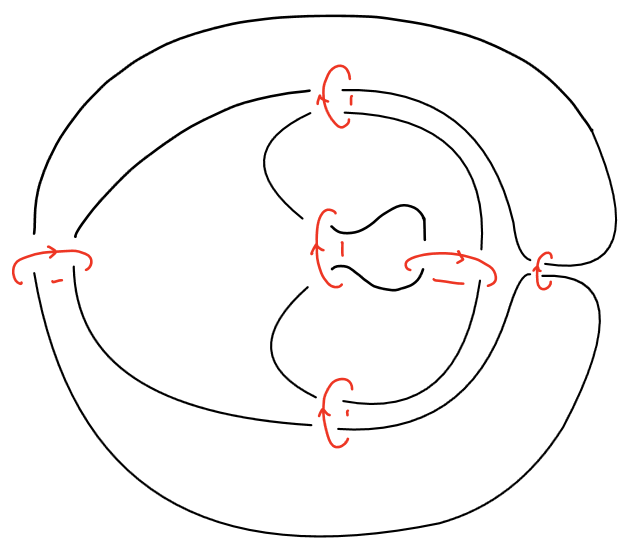
A FAL in or is obtained from the diagram of a link as follows. Let be a link with diagram . We encircle each twist region (a maximal string of bigons) of with a single unknotted component called a crossing circle. The complement of the resulting link is homeomorphic to the link obtained by removing all full-twists i.e., pairs of crossings from each twist region. Therefore, a diagram of the fully augmented link contains a finite number of crossing circles, each encircling two strands of the link. These crossing circles are perpendicular to the projection plane and the other link components are embedded on the projection plane, except possibly for a finite number of single crossings, called half-twists which are adjacent to the crossing circles. See Figure 1.
Lackenby’s cut-slice-flatten method [lackenby] for fully augmented links in produces a decomposition of the link complement into two isometric hyperbolic polyhedra. In [kwon2020] the first author of this paper describes the analog of the cut-slice-flatten method for fully augmented links in .
Definition 2.3.
A fully augmented link diagram in or is a link diagram that is obtained from a twist-reduced diagram of a link in or as follows:
-
(1)
augment every twist region with an augmentation circle
-
(2)
remove all full twists.
See Figure 1.
A fully augmented link in or is a link that has a fully augmented link diagram in or .

Definition 2.4.
A torihedron is a cone on the torus, i.e., , together with a cellular graph on . The graph is called the graph of the torihedron. We refer to the edges (resp. faces) of as the edges (resp. faces) of the torihedron.
An ideal torihedron is a torihedron with the vertices of and the vertex removed; the removed vertices are referred to as its ideal vertices.
The following is a rephrasing of the “base-angled pyramids” from [kwontham]:
Definition 2.5.
Let be a torihedron, with graph . The conical polyhedral decomposition of is the polyhedral decomposition obtained by coning over the cone point, i.e., it has a 3-cell for each face of , a 2-cell for each edge of (in addition to the faces of ), and a 1-cell for each vertex of (in addition to the edges of ).
Definition 2.6.
Let be a torihedron, with graph . Let be a triangulation of obtained from by adding only edges, and let be the torihedron with graph . The conical triangulation of (based on ) is the conical polyhedral decomposition of .
We may say a triangulation is a conical triangulation of if we do not need to be specific about the choice of .
Remark 2.7.
For the polyhedral decomposition of FALs in , one can also obtain a triangulation that refines it by coning over a point, but there is no canonical choice of such a point; we simply make a choice of a vertex of the bow-tie graph, which corresponds to an ideal vertex in each polyhedron.
Remark 2.8.
Let us describe the polyhedral/torihedral decomposition and triangulation of a FAL complement in and that one obtains by the cut-slice-flatten method and some further refinement. Let be a FAL. We first assume that has no half-twists.
Definition 2.9.
Let be a FAL in with no half-twists. For an augmentation circle , denote by the spanning (twice-punctured) disk bounded by ; the projection plane cuts along three arcs, denoted , into two half-disks which we denote by and refer to as the spanning faces.
The arcs separate the projection plane into 2-cells, one for each region of the link diagram of , which we denote by ; we refer to these 2-cells as regional faces.
For in , Lackenby’s ideal polyhedral decomposition of consists of the arcs as 1-cells, the faces as 2-cells, and two 3-cells which are the connected components of minus the 1- and 2-cells.
Definition 2.10.
Let be a FAL in with no half-twists. The definitions of arcs and faces in Definition 2.9 apply to .
Kwon’s ideal torihedral decomposition of [kwon2020] consists of the arcs as 1-cells, the faces as 2-cells, and two ideal torihedra which are the connected components of minus the 1- and 2-cells.
In each torihedron, the conical polyhedral decomposition adds one 1-cell for each augmentation circle , denoted by and one 1-cell for each segment of demarcated by spanning disks, denoted by , connecting them to the cusp of the torihedron, which we refer to as vertical crossing arcs, and one 2-cell for each pair of an augmentation circle and segment that are adjacent, which we denote by and refer to as a vertical face, whose boundary edges are , and (with meaning either or ). 777The notation is ambiguous as it could refer to vertical crossing arcs of the top or bottom torihedron; this should not be a problem as we usually only work with the top torihedron, with the same arguments applying to the bottom torihedron by symmetry.
We thus get a polyhedral decomposition of with the above 1- and 2-cells in addition to those in Definition 2.9, and two 3-cells for each regional face.
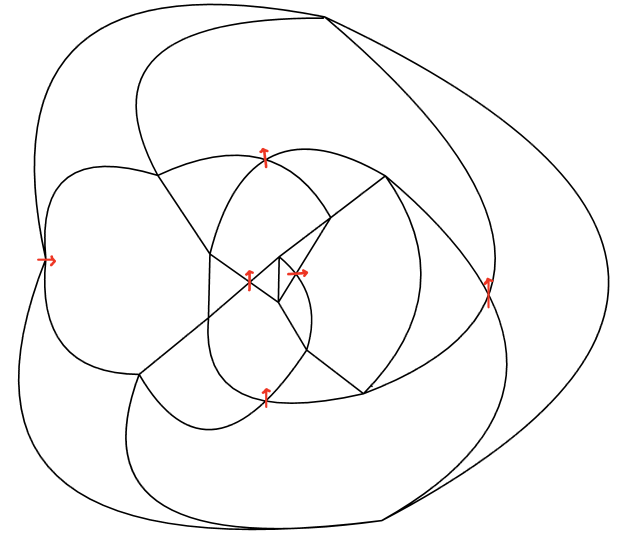
The graph on the boundary of the polyhedra/torihedra is the bow-tie graph of , as described below:
Definition 2.11.
The bow-tie graph of a FAL in or is obtained by removing all half-twists, replacing each augmentation circle by a pair of triangles, “bow-tie”, and shrink each segment of the link to a vertex. See Figure 3.
Next, we describe the same decompositions for FALs with half-twists. The definitions below technically subsume Definitions 2.9, 2.10, but it is easier to describe the no half-twist case first.
Definition 2.12.
Let be a FAL in or , possibly with half-twists. Let be the FAL obtained from by removing all half-twists. The construction of the polyhedral decomposition of is the same as for except for regional faces, which we describe below.
For a region , let be the regional face of . As an ideal polygon, its boundary edges are of two types: for some augmentation circle , or a pair of edges, both or both . Near an edge of the former type, is obtained from by a half-twist, just following the half-twist; near edges of the latter type, is constructed as in Figure 2.
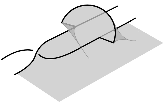
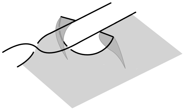
Remark 2.13.
In the case of in , all the vertical arcs and faces are constructed the same as a FAL without half-twists, but may not be as obvious to visualize.
Remark 2.14.
When a FAL has no half-twists, its complement has an obvious symmetry that swaps the top and bottom polyhedra/torihedra, which, in particular, preserves the 1- and 2-cells in the projection plane and swaps the two 3-cells associated with each region.
Suppose has half-twists. Let be the link obtained from by applying this top-bottom symmetry (i.e., flip the crossing at the half-twists). Then the polyhedral decomposition of Definition 2.12 for and are related in two ways:
-
•
by the top-bottom symmetry;
-
•
by performing a Dehn-twist at each augmentation circle that harbors a half-twist.
Thus, the composition of the top-bottom symmetry and then the Dehn-twists is a symmetry on the complement of that preserves the 1- and 2-cells in the projection plane and swaps the two 3-cells associated with each region.
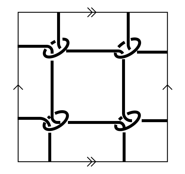 |
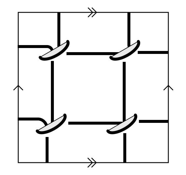 |
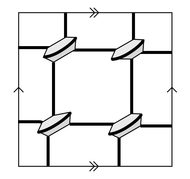 |
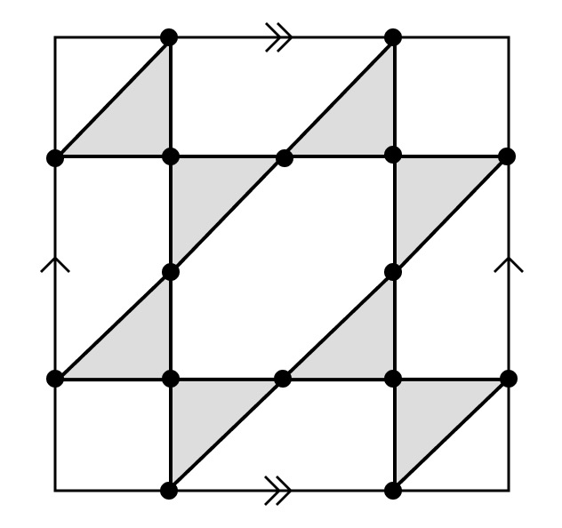 |
| (a) | (b) | (c) | (d) |
2.2.1. Circle Packings and FALs
We briefly recall circle packings and their relation to FALs. In short, the complete hyperbolic geometry on the complement of a FAL is determined by a circle packing, with one circle corresponding to each region of the link. We refer to [purcell] and [kwon2020] for more details.
Definition 2.15.
Let be a surface which is or , and let be a simple graph (typically a triangulation) embedded in . A circle packing realizing in is a collection of circles in , , indexed by the vertices of , such that are tangent if are adjacent vertices in .
(Note that our definition of a circle packing slightly differs from the standard one, in that the interiors of circles are considered as additional data; see e.g. [BandS] for more on circle packings/packings.)
Definition 2.16.
Let be the torus given as a quotient of by a group of translations, and let be a graph embedded in . A circle packing realizing in is a circle packing realizing in that is invariant under , where is the preimage of in .
We allow “accidental” intersections or tangencies of circles, that is, not adjacent in does not imply that are not tangent. We also allow the circles to have interiors that intersect (see Definition 2.19).
Note that in the case, the existence of a circle packing on may impose a constraint on .
In the following definitions, may be one of the surfaces above, and is an embedded simple graph as above.
Definition 2.17.
An interior filling of a circle packing is a choice, for each circle , of a connected component of ; the chosen component is called the interior (region).
Equivalently, it is a choice of orientation of each (the corresponding interior filling begins defined by the region to the left as the interior). Of course, for , a circle packing has a unique interior filling.
The following are some adjectives for interior fillings:
Definition 2.18.
An interior filling is locally order-preserving if the cyclic order on points of tangencies on from the orientation on (i.e., induced by the interior) agrees with the counterclockwise cyclic order on the vertices adjacent to in (imposed by its embedding in ).
Definition 2.19.
An interior filling is locally univalent if the interiors of are disjoint for adjacent vertices of ; if disjointness holds for all pairs of vertices, then we say the interior filling is (globally) univalent. (See [Stephenson].)
Note that if a locally univalent interior filling exists, it is unique, so we may describe a circle packing as locally univalent.
Univalence implies the resulting graph of tangencies (vertices are the circles, edges are tangencies) is isotopic to (or the image of under a diffeomorphism of ). In fact, in our use case, it is a local condition:
Lemma 2.20.
Let be a circle packing of a triangulation of or , with a choice of interior filling. Then univalence is a local condition in the following sense: if the interior filling is locally order-preserving and locally univalent, then the interior filling is univalent.
Note that there is no finiteness condition on .
Proof.
First, observe that if a vertex of has degree 2, then since is a triangulation, the only possibility is that , and consists of three vertices, all connected to each other, so there is nothing to prove. Hence let us assume that the degree of every vertex of is at least 3.
Let be the dual graph to , which has a natural “transverse to ” embedding in (uniquely defined up to isotopy). Let be the region of corresponding to vertex of . We show that there is a map from to itself that sends and its interior into for each vertex , which would immediately imply univalence.
Consider a triangular region of between vertices . The interiors of are pairwise disjoint. Let the points of tangencies among the ’s be , with between and .
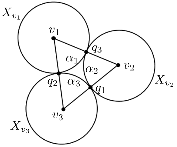
There are two arcs of between and ; by locally order-preserving-ness, and , exactly one of these arcs has no other points of tangencies. Let be this arc. Similarly define . These three arcs enclose a region that is exactly one of the connected components of the complement of the union of and their interiors. Pick a point in this region, and draw curves from each to within this enclosed region.
It is easy to see that these points and the curves we draw to the points of tangencies make an embedded graph that is isomorphic to ; the self-diffeomorphism of sending this graph to would send and its interior into , hence we are done. ∎
Definition 2.21.
Let be a FAL in (resp. ) with bow-tie graph in (resp. ). The region graph, denoted by , is the embedded graph consisting of a vertex in each non-bow-tie region of , and an edge for each vertex of (which connects the two non-bow-tie regions adjacent to it). The faces of correspond bijectively with bow-tie faces, hence is a triangulation of (resp. ).
A univalent circle packing on determines geometries on the polyhedra in the (conical) polyhedral decomposition of the link complement, which follows from the observation that the graph on ( or ) with vertices given by the points of tangencies of the circle packing and edges connecting neighboring points of tangencies on a circle is precisely the bow-tie graph . In fact, this is the complete hyperbolic geometry on the link complement:
Lemma 2.22.
Let be a FAL in (resp. ) and let be its region graph in (resp. ). A univalent circle packing on is unique up to conformal maps, and determines the geometry of the polyhedra in the polyhedral (resp. conical polyhedral) decomposition of the link complement that makes it complete hyperbolic; that is, the complete hyperbolic metric on the link complement determines a realization of each polyhedron as an ideal hyperbolic polyhedron, whose ideal vertices are the points of tangencies of the circle packing.
Proof.
For uniqueness, see [koebe] and [BandS]. For circle packing to geometry, see [lackenby] and [kwon2020]. ∎
3. Extensions of the TT method
We consider an extension of the TT method to links in the thickened torus, which basically amounts to adding more crossing arcs between the link and the cusps of . We also consider modifications of the TT method that are adapted to FALs in and , which, in particular, avoids some redundancies.
While it is quite easy to find the right extensions/modifications, we proceed in a more systematic manner, namely by generalizing the TT method to 3-manifolds with toric boundaries together with a polyhedral decomposition. Then we realize these extensions/modifications of the TT method as applications of the generalized method to the link complements together with some natural polyhedral decomposition.
3.1. Generalization to 3-Manifolds with Toric Boundary
Consider a compact 3-manifold with toric boundaries , with at least one boundary component. For each boundary component , choose a simple closed curve .
Let be an ideal polyhedral decomposition of ; its truncation, , is a polyhedral decomposition of a truncated , which is naturally identified with . Each vertex of lies on the boundary, and is incident to exactly one interior 1-cell. The internal 1-cells of are in bijection with the 1-cells of ; the boundary 1-cells of are in bijection with corners of 2-cells of , that is, a boundary 1-cell comes from the truncation of a 2-cell at one of its corners. The boundary of each internal 2-cell of consists of 1-cells that alternate between boundary 1-cells and internal 1-cells.
Associate to each internal 1-cell a crossing label , and to each boundary (oriented) 1-cell an edge label .
A collection of labels is an algebraic solution if it satisfies:
-
•
Normalization: For each boundary component , if is a sequence of 1-cells in such that their concatenation is homotopic to , then ;
-
•
Region equations: For each oriented internal 2-cell , with boundary 1-cells in that order, their labels satisfy
(3.1) in ;
-
•
Edge equations: For each oriented boundary 2-cell , the sum of edge labels in its boundary is 0, i.e., ; equivalently, we may write this in an analogous form as above:
(3.2)
If has a complete hyperbolic geometry, we can construct geometric labels just as in Section 2.1, that is, for each boundary component, take the horosphere such that the chosen closed curve has length 1, and identify the lifts of in the universal cover of with so that the lifts of are identified with ; then the definition of geometric crossing and edge labels follows exactly as in Section 2.1. The geometric solution is easily seen to be an algebraic solution (see Section 2.1.1).
Remark 3.1.
The original TT method, as laid out in Section 2.1, is obtained from taking the Menasco decomposition. As suggested by the names of the labels, the internal 1-cells correspond to the crossing arcs, the boundary 1-cells correspond to the peripheral edges, the vertices correspond to peripheral endpoints.
Remark 3.2.
The (generalized) TT method may be thought of as equations defining a flat connection in a lattice gauge theory on the 1-skeleton of under a certain choice of gauge. A connection is an assignment of a matrix to each oriented edge of , and flatness of the connection means the product of these matrices along the boundary of a 2-cell of is 1.
An algebraic solution defines a connection as follows: to the edges of of type , we assign matrices as in (2.7) (using labels from , not the geometric labels), and to an edge of corresponding to a meridian, we assign the upper-triangular matrix . The region/edge equations (3.1,3.2) ensure that this connection is flat.
As we saw in Remark 2.2, the act of changing the choice of peripheral torus and the identification of its lift with transforms the labels by some scalings; this can be seen as a particular type of gauge transform, namely with the gauge group element , where indexes peripheral tori, and are of the form
3.2. Extension to Links in the Thickened Torus
We apply the generalized TT method above to a polyhedral decomposition of , closely related to the torihedral decomposition (see Definition 2.4), which we describe below. Note that one could identify with the complement of the Hopf link in , then apply the original TT method directly to , but this feels somewhat unnatural.
Let be a link in with a cellular link diagram . Let denote the top and bottom cusps of , i.e., , . Choose simple closed curves , e.g. we may take the curves that correspond to the meridians of the Hopf link (in the identification ).
For each crossing of , let be the crossing arc at . For a region of , with boundary consisting of edges and vertices , let be an ideal polygon embedded in with sides and ideal vertices at segments of ; the interior of should project homeomorphically onto under the link projection. We call a regional face.
The union of all the ’s separates into two pieces. Denote the piece connected to by respectively.
An overpass segment refers to a maximal segment of the link (or equivalently, a maximal contiguous sequence of edges of ) that lies between two underpasses, and similarly for an underpass segment. We say an overpass segment runs over if goes over a crossing which is an endpoint of ; we say are adjacent if one runs over the other.
For each overpass segment , let be a crossing arc 888 We refer to these arcs as crossing arcs even though they are not indexed by crossings, because they play a similar role to ’s, and can in fact be thought of as crossing arcs when is considered as a link in the complement of the Hopf link, . that travels from a point of to . Likewise, for each underpass segment , let be a crossing arc that travels from a point of to . For each pair of adjacent overpass segments , with running over at the crossing , let be the ideal triangle in with sides and ideal vertices at . Similarly construct for adjacent underpass segments meetings at crossing . We call and vertical faces.
For each region of , the union of vertical faces for adjacent to , together with , cuts out a volume above ; since is cellular, is a disk, so is a ball. Similarly, we get a volume below (connected to ).
We thus have an ideal polyhedral decomposition of , where the 3-cells are the volumes , the 2-cells are regional faces and vertical faces ,, the 1-cells are crossing arcs .
The truncation introduces more notation. Instead of cutting off the ends of , we describe the boundary vertices/1-cells/2-cells on peripheral tori as in Section 2.1. For crossing arcs corresponding to crossings, we again refer to their peripheral endpoints by . For crossing arcs corresponding to an overpass segment , we have one peripheral endpoint at and another one near . Likewise, for underpass segment , has peripheral endpoint at and another one near .
As in Section 2.1, we have peripheral edges which comes from the intersection of regional faces with the peripheral tori. The vertical face gives rise to three new types of peripheral edges:
-
•
connecting to when ends at ,
-
•
connecting to when runs over ,
-
•
connecting to at .
The peripheral endpoints and peripheral edges on the peripheral torus at make up a graph, which we refer to as the overpass graph; likewise, the underpass graph is the graph consisting of vertices and edges at . The regions of these graphs are in bijection with the regions of .
The overpass graph can be obtained from the link diagram of by essentially a quotient operation, as follows (similar to the underpass graph). Start with . For each overpass segment that does not go over any crossings, we add a vertex to the middle of , the edge of which naturally corresponds to, splitting into two edges. For each overpass segment that goes over at least one crossing, we collapse those crossings that goes over (and the edges between themselves) into one vertex. The resulting graph has vertices in bijection with overpass segments, and the degree of a vertex is , where is the number of crossing that runs over. It is straightforward to check that the resulting graph is isomorphic to the graph on the peripheral torus of .
Note that if is alternating, then the overpass and underpass graphs are isomorphic to the link diagram of .
3.2.1. Equations for Thickened Torus Case
We consider the equations imposed on labels that form an algebraic solution.
The region equations (2.6) and edge equations (2.1) must be satisfied by all the “old” edge and crossing labels, i.e., labels on the crossing arcs for crossings and peripheral edges from regional faces. They must satisfy additional equations, as follows.
The two peripheral edges between and for an overpass segment that goes over a crossing , differ by exactly a meridian, so by the normalization condition on an algebraic solution, we have the following equation, which we also call an edge equation:
| (3.3) |
where is to the left of the segment , and on the right, and we orient both peripheral edges from to .
There is also a region equation arising from each vertical face . Let overpass segment run over at a crossing . The truncated has edges (here the superscript stands for or , whichever is relevant to this triangle). The consequence of (2.3) is the following vertical region equation:
| (3.4) |
Intuitively, the “shape parameters” as in (2.2) must be 1.
Remark 3.3.
Suppose we’ve solved for the old edge and crossing labels. One can get quite far from just knowing for some arc and for some adjacent crossing. Say is an endpoint of . It is clear that (3.4) determines the other three labels, in particular and . Say is ; then is determined. Then we can consider the next arc that is next to (at ). Again it is clear that (3.4) determines and . Let be the next crossing (other endpoint of ). Then from the old edge labels, we can get the difference , which is equal to , and thus we get . We can continue in this manner until we return to .
3.3. FALs in
We apply the generalized TT method of Section 3.1 to the polyhedral decomposition of the complement of FALs in described in Definitions 2.9, 2.12.
As in Section 3.2, we would need to consider the truncated version of this polyhedral decomposition. In the following, we spell these out in detail, in terms of crossing arcs, peripheral edges, and equations on the labels; this will be similar to the modified TT method described in [rochyTT].
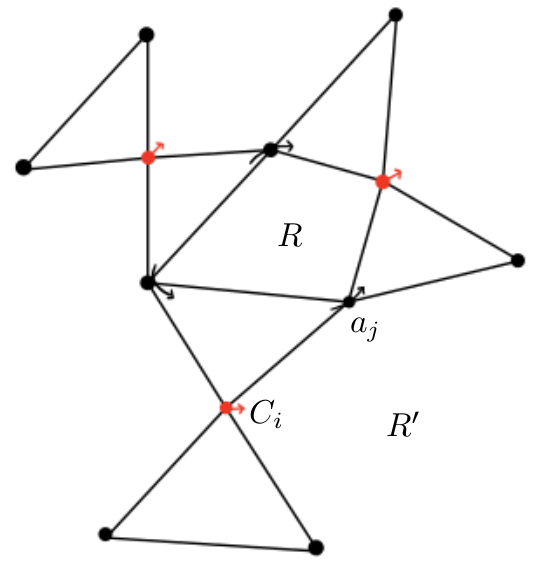
Let be the link diagram of after removing full twists. Let be the bow-tie graph for . Let be the collection of augmentation circles of . Let be the collection of segments of demarcated by spanning disks. See Figure 5.
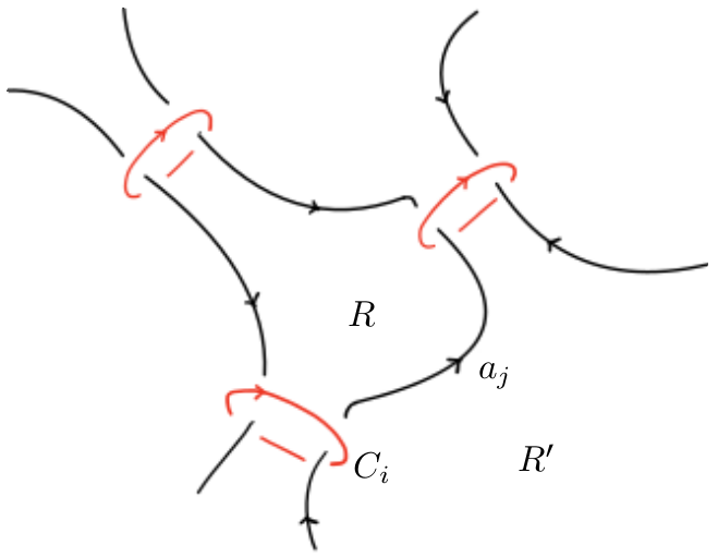
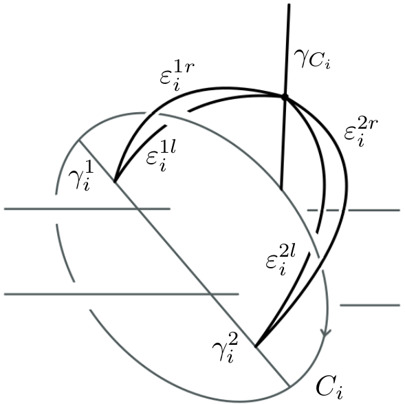
The truncation of the spanning face has six sides, with three peripheral edges denoted opposite the three crossing arcs . The circle intersects two regions, giving two peripheral edges denoted , with the top of oriented from to . See Figure 6 for orientation conventions.
Each segment meets two regions, giving peripheral edges denoted , with from the region to the left of . See Figure 7 for orientation conventions.
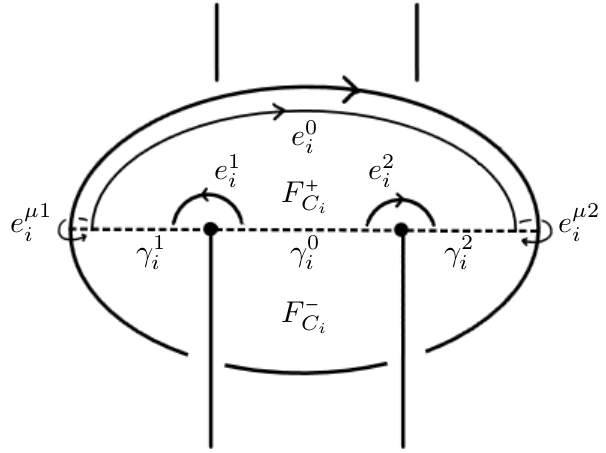
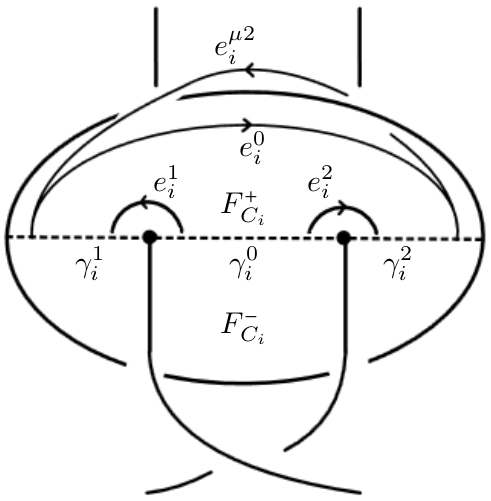
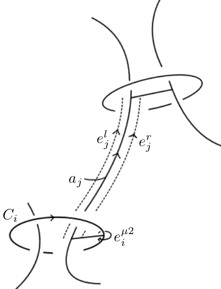
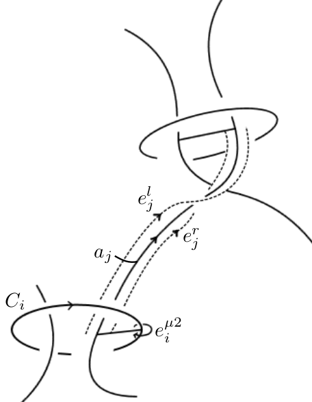
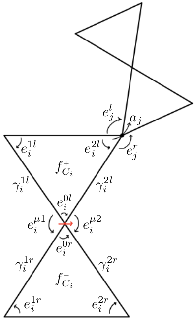
Recall that there is one 2-cell , the regional face, for each region of , and two 2-cells, the spanning faces, , for each augmentation circle , which have boundary consisting of . Writing for , is made into two copies in , making up the two triangles in the bow-tie corresponding to , which we label and . The crossing arcs and peripheral edges in the boundary of (the truncated) likewise split into two copies in .
The edges of correspond to crossing arcs; the peripheral edges are recorded in as tiny arcs near vertices.
As usual, one considers the equations that would make labels on these crossing arcs and peripheral edges an algebraic solution, for example, the edge equation from a segment is simply
Remark 3.4.
The polyhedral decomposition respects the -symmetry of reflecting the link in the plane of the diagram, which naturally leads to constraints on the geometric labels. These constraints and some other “positivity” constraints turn out to be sufficient to prove that an algebraic solution satisfying these constraints is indeed geometric. This discussion will be elaborated on in Section 4.2.
3.4. FALs in
We repeat Section 3.3 but for FALs in , namely, we apply the generalized TT method of Section 3.1 to the polyhedral decomposition of the complement of FALs in described in Definitions 2.9, 2.12.
The same discussion involving spanning and regional faces can be repeated verbatim. The vertical faces introduce new peripheral edges. We consider only the top torihedron, the bottom being identical.
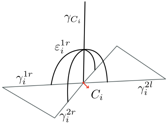
Each vertical arc is adjacent to four vertical faces, one for each segment meeting the spanning disk of . These peripheral edges are denoted by ; here the 1 or 2 in the superscript indicates which of or is an endpoint, and the or indicates on which side of it is, similar to Figure 8; see Figure 9.
Each vertical arc is adjacent to four vertical faces, one for each crossing arc meeting ; if travels from augmentation circle to , then these crossing arcs are . These peripheral edges are denoted by .
For the region equations on the algebraic solution, we leave it as an exercise for the reader to recover them (see Section 3.2.1, Section 5).
Remark 3.5.
Given a geometric solution to the TT method, it is easy to obtain the cusp shapes of the peripheral tori. For a peripheral torus , which has a chosen meridian, consider a sequence of peripheral edges whose concatenation forms a closed loop that is homotopic to a longitude of the peripheral torus. Then the sum is the cusp shape of .
4. From Algebraic Solutions to Geometry
4.1. Sufficient Criterion on Algebraic Solutions to be Geometric
We present a sufficient criterion on an algebraic solution to the generalized TT method on a compact 3-manifold with toric boundary components (as in Section 3.1) that implies that is the geometric solution. We describe a procedure to assign shape parameters to an each tetrahedron of a triangulation . The sufficient criterion is simply that the shape parameters assigned have negative imaginary part; we find that the Thurston gluing/completeness equations are then automatically satisfied. (See Theorem 4.9.)
Practically speaking, this sufficient criterion is only useful if is a geometric triangulation, which is a fact that is often not easy to know or verify. The description of the procedures to get the shape parameters and the developing map (see Section 4.1.2) may be of independent interest; for example, the developing map must be surjective if the algebraic solution is geometric, a fact which one can use as a necessary criterion of geometric-ness.
We fix an 3-manifold with a polyhedral decomposition , and we fix an algebraic solution to the generalized TT method (which is, importantly, not necessarily geometric). We denote by , and the corresponding ideal polyhedral decomposition. As usual, we may identify the truncation of with itself, and accordingly identify with the truncation of .
4.1.1. Assigning labels to arbitrary arcs and peripheral edges
Let be an arc between cusps of which is not homotopic to a curve contained in some neighborhood of an ideal vertex (e.g. is an edge in the triangulation). For such an arc, denote by the portion between peripheral endpoints, i.e., .
If we understood the hyperbolic geometry of , we may assign a crossing label to as in Section 2.1, having absolute value and argument given by comparing meridians at the endpoints of . However, we want to obtain in terms of the given .
The following procedure produces some crossing label that would be consistent with the hyperbolic geometry if the algebraic solution was indeed the geometric one.
Let the peripheral endpoints of (intersection with peripheral tori) be and ; orient from to (end result is independent of choice of orientation). It is possible to homotope into a concatenation of curves , such that are 1-edges of , and are peripheral edges which are in for , while are new peripheral edges connecting to endpoints of respectively. Note that here we orient in accordance with , which may disagree with the orientations that may be imposed by convention, e.g. in the original TT method.
We define to be solutions to the following equation ():
| (4.1) |
where means equality in , i.e., up to nonzero scalar. Rearranging, we have
| (4.2) |
from which can be easily obtained. Well-definedness of is shown in Proposition 4.3 below.
The definition above is motivated by considering the situation where we know that the algebraic solution given is the geometric solution. Place so that we are in -centered view (see Section 2.1.1). As we successively traverse the curves, hopping from peripheral endpoint to peripheral endpoint, we perform the isometry on that takes us to the view centered on the next peripheral endpoint. The composition of these isometries must be equal to the isometry by traversing directly. This results in (4.1).
Next we consider peripheral edges not in . Given two arcs as above that emanate from the same cusp, we can consider a peripheral edge from to , where are the peripheral endpoints of at the common peripheral torus, respectively. Let , , as in the construction above. Let be the endpoints of (which are not ) respectively. Let be some concatenation of peripheral edges in homotopic (in the peripheral torus) to . We define
| (4.3) |
Again, well-definedness of is shown in Proposition 4.3 below.
In the following, we will abuse notation by dropping the overline from , as it should be clear which we are referring to.
Before we proceed, let us introduce some notation:
Definition 4.1.
For a curve that is a peripheral edge or crossing arc in , we define to be the matrix given by (2.7) (using labels from , not the geometric labels), which represents the isometry used to traverse . More generally, for a concatenation of such curves, we define to be the composition .
Note that is contravariant with respect to composition, i.e., , which is natural in terms of order of operation, since the ’s, as matrices and isometries of , act to the right.
Lemma 4.2.
For any two homotopic curves that are concatenations of peripheral edges or crossing arcs in , we have .
Proof.
Proposition 4.3.
Proof.
Suppose is homotopic to a concatenation of crossing arcs and peripheral edges in two ways as in the construction above, say and . We want to show that the crossing labels for that the construction above yields using these two presentations of are equal.
Let be a concatenation of peripheral edges in that is homotopic (in the relevant peripheral torus) to ; similarly, let be a concatenation of peripheral edges in that is homotopic (in the relevant peripheral torus) to .
Let , , . By definition, and are homotopic (to ), so by Lemma 4.2, .
Thus we have
Since and lie in a peripheral torus, and must be strict upper triangular, hence by some basic algebraic argument, the above equality implies that they must both be identity. This immediately implies , and , . The well-definedness for labels associated to peripheral edges between arbitrary crossing arcs follows easily from this as well. ∎
A similar argument shows that we have the analog of Lemma 4.2 for an arbitrary collection of crossing arcs, peripheral edges (not just those from ):
Lemma 4.4.
For any two homotopic curves that are concatenations of arbitrary peripheral edges or crossing arcs, we have .
4.1.2. Algebraic solution to piecewise geometry
Let be an ideal triangulation of . Each ideal tetrahedron inherits an orientation from the 3-manifold.
Definition 4.5.
A piecewise geometry on is a collection of surjective maps , where is an ideal hyperbolic tetrahedron considered up to isometries of , and is considered up to homotopy fixing the vertices of ; equivalently, it suffices to record as a function on the set of vertices of , valued in , considered up to linear fractional transformations. can be degenerate, and may be orientation reversing.
We denote by the shape parameter of along , or in terms of the vertices, , where the are the locations of the vertices of corresponding to the vertices of , ordered so that and is the orientation of (see the definition of from Section 2.1).
Note that we place no restriction on , in particular, the imaginary part of can be 0 ( is flat) or positive ( induces a homeomorphism that is orientation-reversing). This is useful for interpreting algebraic solutions to the TT method as describing “geometries” on .
Definition 4.6.
Let be a triangulation with a piecewise geometry. Let be an edge of . Let be the tetrahedra encountered as one traverses around .
We say that weakly satisfies the Thurston gluing equation at if .
We say that strongly satisfies the Thurston gluing equation at if , , and , where is the lift of with argument in .
The latter is the usual definition of Thurston gluing equations [thurston].
We describe a developing map for based on , which in particular defines a piecewise geometry on . Let be a universal cover of Let be the lift along of the polyhedral decomposition of to , and likewise let be the lift of along . The algebraic solution lifts to a collection of labels by pullback, i.e., for any crossing arc and peripheral edge in , we define . 999 is essentially an algebraic solution on , but technically we have not generalized the TT method to such manifolds, though it is quite easy to see how to do it. We denote by the matrices based on the labels as in Definition 4.1.
Choose a polyhedron , a vertex of , and an edge meeting . Let and let be the horizontal plane at height 1, with the identification with by projection. This will serve as our reference point for the developing map.
We first describe where vertices of go. Let be a vertex of . There is a unique up to homotopy arc from to , and let be the peripheral edge between and near (if then is the constant path).
We assign to the point and horosphere which are obtained from and by applying the isometry defined by ; comes with an identification with given by precomposing that of with .
Suppose we chose a different starting point and edge , which yields assignments ; these are related to by a global an isometry, as follows: Let , where is the crossing arc between and are peripheral edges from to (if , we take to be the peripheral edge between ). Write . Then by definition, sends to ; more generally, for any vertex of , if is the path used to define , and for , that is, , , then since , we have . (The identification of the with with that of , as we can already see for , but the difference is only a translation, which ultimately does not affect any results.)
An immediate consequence of the above observation is that the assignments are covariant with deck transformations of .
It is clear from the “-centered view” perspective (Section 2.1.1) and invariance/well-definedness of labels (Section 4.1.1) that the geometric labels attained from the construction of horospheres above agrees with - more precisely, for any arc in between vertices , the construction above gives points and horospheres centered about them with some identifications with , such that the geometric crossing label associated to the geodesic between is , and likewise for peripheral edges in .
In particular, for a tetrahedron , we obtain an ideal tetrahedron with vertices , where are the vertices of , such that the labels of the edges of agree with the geometric labels of the edges of ; maps can be chosen such that they agree with neighboring tetrahedra on their faces.
The developing map is simply the union of the maps on .
By covariance with deck transformations, the ’s and ’s descends to a piecewise geometry on , which we refer to as the piecewise geometry induced by .
Proposition 4.7.
Let be the piecewise geometry on a triangulation induced by an algebraic (not necessarily geometric) solution to the TT method. Then weakly satisfies Thurston gluing equations at every edge.
Proof.
Let be an edge of , and let be one of its vertices. Let be the peripheral torus at . Let (possibly with repetitions) be the tetrahedra of that meet . They intersect in triangles ; let these be arranged in counterclockwise (as viewed from ) order around . Let , oriented away from . Then by definition, . Clearly these multiply to 1. ∎
4.1.3. Sufficient criteria on to be geometric
Before we come to the main result, we state a lemma that will be applied to the peripheral tori to show that under “all positive orientation” condition, the Thurston gluing equations are strongly satisfied at edges:
Lemma 4.8.
Let be an oriented torus with a cellular decomposition (in particular, a triangulation). For each 2-cell of , assign a Euclidean similarity structure compatible with the orientation on - concretely, a Euclidean similarity structure is a simple (i.e., non-self-intersecting) polygon in considered up to Euclidean similarity transforms.
Suppose for each vertex , the Euclidean similarity structures of the 2-cells around it are “weakly Euclidean”, in the sense that there is a well-defined map from the star of to obtained by “unfolding” the 2-cells with the similarity structure; more precisely, if are the 2-cells around in counterclockwise order, with being the edge between and , then an “unfolding” is a choice of representatives of the similarity structures for such that adjoins along the edge corresponding to , and we require that (exactly, not up to similarity transform).
Let the local degree of at be the number of times the “unfolding” map above winds around , or more concretely, it is the sum of angles at in from to , divided by .
Then weakly Euclidean implies that the local degree at is 1 for every vertex, i.e., the Euclidean similarity structure extends over all of .
Proof.
The Euclidean similarity structures define a developing map ; under the developing map, loops in avoiding the vertices of get a well-defined turning number. The boundary of a fundamental domain of must have turning number 1. By invariance of turning number under regular homotopy, and studying how turning number changes under connect sums, we can conclude that there cannot be singularities. ∎
Theorem 4.9.
Let be a triangulation of a 3-manifold with toric ends. Let be an algebraic solution to the generalized TT method, and let be the induced geometry on . If has negative imaginary part for all , then is the geometric solution.
Proof.
By Proposition 4.7, the induced geometry weakly satisfies Thurston gluing equations at every edge. We want to show that it also satisfies it strongly.
Let be an edge of , and one of its endpoints. Consider the peripheral torus of ; it has a triangulation obtained by intersection with . The induced geometry on tetrahedra of induces a Euclidean similarity structure on each of the triangles in . By Lemma 4.8, the local degrees of at vertices of is 1, which implies, in particular, that the induced geometry on is strongly Thurston at .
It remains to check that the induced geometry is complete at ideal vertices. Observe that the edge labels give more than Euclidean similarity structures on the triangles of - they actually give a triangle in up to translations. Thus, in the developing map of a peripheral torus, the -action consists of only translations, and hence the induced geometry is indeed complete at ideal vertices. ∎
4.2. FALs: Necessary and Sufficient Criteria on Algebraic Solutions to be Geometric
4.2.1. Necessary Criteria
We present criteria on an algebraic solution to the TT method for a FAL that are necessary for it to be the geometric solution:
Lemma 4.10.
Let be a FAL in or . Recall the notation for crossing arcs and peripheral edges from Sections 3.3, 3.4. Let be an algebraic solution to the TT method. If is geometric, then the labels satisfy the following criteria: (with indexing augmentation circles and indexing segments ):
-
•
,
-
•
, ,
-
•
,
-
•
,
-
•
,
-
•
.
(The signs on the second line depend on whether the peripheral edge agrees in orientation with the meridian of the segment.)
Proof.
The first item is true by definition, and the rest are simple consequences of the top-bottom symmetry by reflection (see Remark 2.14 for FALs with half-twists); e.g. the symmetry fixes peripheral edges , but performs an anti--linear automorphism on the peripheral torus of which flips the meridian to , hence must be pure imaginary. ∎
Lemma 4.11.
With the same setup as Lemma 4.10, if is geometric, then satisfies:
-
•
;
-
•
.
Proof.
Follows from Remark 2.8. ∎
Lemma 4.12.
Let be as in Lemma 4.10. Let be a non-bow-tie region of the bow-tie graph of . Let be an edge of , and let be any pair of non-intersecting diagonals of that share vertices with ; these ’s correspond to crossing arcs in the link complement.
Let be the shape parameter at as given by (2.2), i.e., , where are the peripheral edges from to respectively.
If is the geometric solution, then satisfies the following criteria: is real and .
Proof.
If are also edges of , then the fact that must be real follows directly from Lemma 4.10; this means that every four consecutive vertices of must lie on a common circle, hence is circumscribed, and it follows that is real for any as well.
We may also prove real-ness by the following more geometric argument, which leads more naturally into the rest of the proof. From the top-bottom reflection symmetry, it follows that can be isotoped to lie in a geodesic plane, and in particular, that the vertices of lie on a circle in the sphere at infinity. This implies that the shape parameters are real.
Moreover, the polygon formed by must be a convex polygon. Thus, if the path traverses the vertices , and are placed that , then is placed at the shape parameter , and then convexity of the polygon formed by implies that . ∎
4.2.2. Sufficiency of Criteria of Section 4.2.1
Theorem 4.13.
Let be a link obtained from fully augmenting a link in (resp. ) with bow-tie graph in (resp. ). Let be the region graph of (see Definition 2.21).
Then an algebraic solution to the TT method that satisfies the criteria in Lemma 4.10 determines a unique circle packing realizing up to orientation-preserving conformal transformations of ; moreover, if in addition it satisfies the criteria in Lemma 4.11 and Lemma 4.12, then the circle packing is univalent.
Proof.
We first work with the case where the link is in ; we deal with the case later, which only needs some minor modifications.
Consider the developing map from Section 4.1.2. Let be the polyhedron (3-cell) in the polyhedral decomposition of that lies above the projection plane (see Definition 2.9). The developing map sends the vertices of to . We need to show that if satisfies the criteria of Lemma 4.10, then these vertices are the points of tangencies for a circle packing on , the region graph of .
As noted in the proof of Lemma 4.12, the criteria of Lemma 4.10 implies the real-ness of some shape parameters, which means the vertices of lie on a circle; we denote this circle by .
Let be an edge of the region graph connecting vertices of ; in terms of the bow-tie graph , is a vertex of that meets regions and . If corresponds to an augmentation circle of , then the first of the criteria, , implies that and are tangent, while if corresponds to a segment of , then the second item of the criteria, , , implies that the circles are tangent. (These are easiest to understand by placing at , so that become straight lines, and these criteria imply that the lines are parallel.) Thus, is a circle packing for .
Now suppose also satisfies the criteria of Lemma 4.11 and Lemma 4.12. The criterion of Lemma 4.12 implies that the vertices of appear in order along , i.e., we can orient so that is locally order-preserving. Then it is easy to see that the criteria , imply that the circle packing is locally univalent. Hence, by Lemma 2.20, is univalent.
Next we prove the converse. Let be a circle packing realizing .
We need to choose horospheres for each vertex of , and identifications with . Place at . Suppose corresponds to an augmentation circle of . Let be the edges of meeting , as in Figure 8, and let be their endpoints besides . Let be the region that meets , let be the region that meets , and let be the regions adjacent to respectively (in Figure 8, the red arrow in the middle of the bow-tie sits at and is pointing from to ; are the (non-bow-tie) regions above and below respectively).
Since is at , the circles are parallel lines, and are circles tangent to both lines. The vertices etc. are the points of tangencies among these circles, more specifically, ; hence, they form a rectangle. Thus, it is possible to choose so that ; we can choose to be the horizontal plane at a height such that the intersection points of with are distance 1 apart in , and choose the identification with so that the peripheral edge , which runs from , is identified with 1. It also follows immediately that .
Suppose corresponds to a segment of Then a similar procedure and analysis shows that we can choose so that for the peripheral edge (as in Figure 8; in general of the form ), we have (here the sign is iff agrees in orientation with the meridian of ). Thus, we can guarantee the second item , , of Lemma 4.10. The third item also follows immediately because peripheral edges form a rectangle as before. Then the fact that the vertices of are on a circle means that shape parameters are real, hence implying the remaining items and .
Now suppose is univalent. Being local order-preserving means that any such from Lemma 4.12 forms a convex quadrilateral, hence the shape parameter is between 0 and 1. Local univalence implies the criteria of Lemma 4.11, i.e., , . To see this, consider a point of tangency that corresponds to an augmentation circle . Keeping with the notation above, suppose we arrange the parallel lines to run vertically, with on the left of . Then and point vertically upwards. By local univalence, neighboring circles must lie between them, so the interior region of must lie to its left, and the interior region of must lie to its right. The edge runs horizontally from to , so by comparing with , we see that . The case of corresponding to a segment is dealt with similarly.
Finally, we address some modifications to the argument for FAL in . A circle packing realizing is equivalent to a circle packing in realizing its universal cover that is invariant under a lattice group of translations of the plane. Instead of a polyhedron , we consider the top torihedron , and consider a copy of its universal cover in . The developing map sends vertices of to , which should serve as the points of tangencies of a circle packing realizing . All the arguments essentially hold verbatim, one just has to ensure the constructions are co-/invariant with respect to the group of translations. We note that in the arguments above, we often send some point to , but this is merely for convenience/intuition, so the arguments still hold even though we are working with circle packings in rather than in . ∎
Corollary 4.14.
Let be as in Theorem 4.13.
5. Examples
The following example is the TT method on the standard Square Weave in the thickened torus.
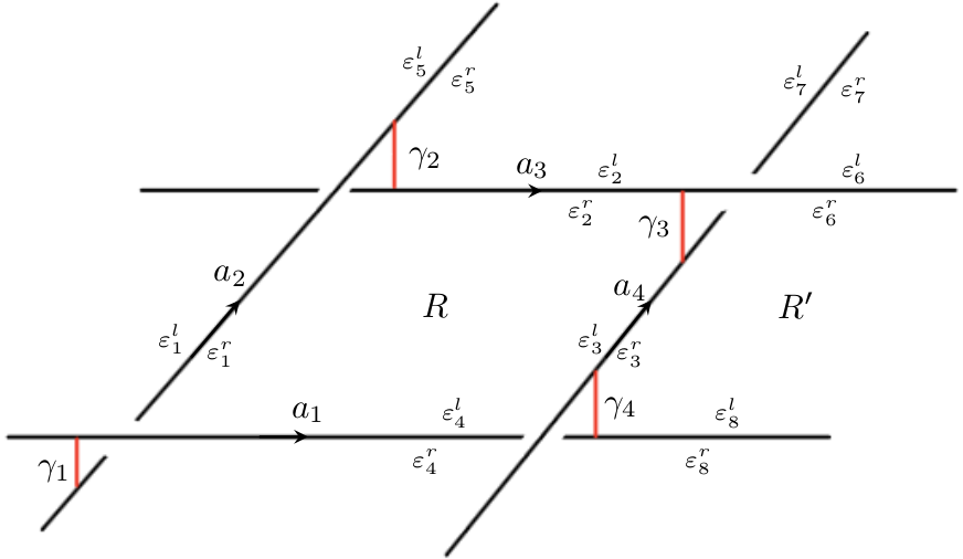
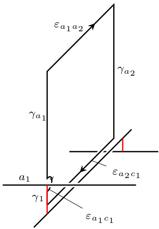
We first deal with labels from the old TT method. The edge equations of the TT method give us the following set of equations.
| (5.1) |
Under a symmetry of the left diagram in Figure 10, namely the clockwise rotation by preserving , the peripheral edges and crossing arcs get sent to each other:
| (5.2) |
Note that the meridians also get sent to meridians, but with sign changes: If refers to the meridian on the overpass segment , then
| (5.3) |
Thus, we have:
| (5.4) |
We get the following shape parameters for the region :
| (5.5) |
As one would expect from the rotation symmetry, the shape parameters above are all equal.
The shape parameters satisfy the following relations (from in (2.4)):
| (5.6) |
Since , each of the above relations reduce to .
By applying the same process to , we have , and , where . But we also have, by edge equations (5.1), that . So we have .
Thus we have , from which we obtain and
Observe that reflection of the link diagram across a link component, say , is a symmetry of the link diagram, which induces an orientation-reversing homeomorphism of the link complement that also fixes each link component, thus acts on each peripheral torus by an anti--linear automorphism. For example, this symmetry sends to and thus acts as ; since it sends to , we have , which is consistent with .
Next, we solve the equations involving new crossing labels and edge labels, i.e., those involving (the Hopf link components).
The vertical region in Figure 10 gives rise to a vertical region equation as in (3.4). It is a truncated ideal triangle bounded by crossing arcs and peripheral edges , and we have:
| (5.7) |
The symmetry of reflecting across preserves the vertical region in Figure 10, so . Symmetry across gives .
Note that depends on the choice of meridian on ; we choose the meridian to be homotopic to , so that .
Then from (5.7),
| (5.8) |
The clockwise -rotation about of the diagram sends to , so we must have, and indeed we do, . The rotation sends the meridian at to , and further careful consideration shows that we must have , and thus we pick out a sign for of (5.4):
| (5.9) |
Note that choosing the other sign would give the algebraic solution for the same link complement but with reversed orientation (since the rotation would send the meridian at to ).
All other labels are obtained by symmetry (e.g. rotating by about a crossing). The algebraic solution is unique, and hence is also the geometric solution.
Example 5.1.
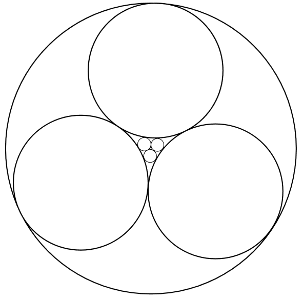
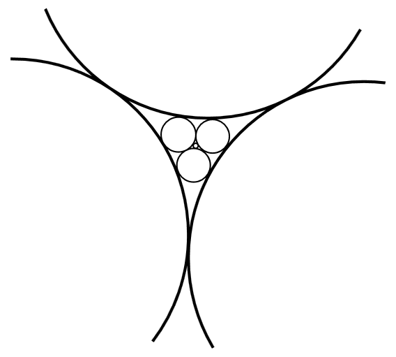
In Figure 11, we present an example of a FAL in with more than one algebraic solution to the TT method. By the correspondence between algebraic solutions and circle packings discussed in Theorem 4.13, we describe two such solutions, one geometric and the other not geometric, by presenting their corresponding circle packings.
