Droplet jumping by modulated electrowetting
Abstract
We investigate jumping of sessile droplets from a solid surface in ambient oil using modulated electrowetting actuation. We focus on the case in which the electrowetting effect is activated to cause droplet spreading and then deactivated exactly at the moment the droplet reaches its maximum deformation. By systematically varying the control parameters such as the droplet radius, liquid viscosity, and applied voltage, we provide detailed characterisation of the resulting behaviours including a comprehensive phase diagram separating detachment from non-detachment behaviours, as well as how the detach velocity and detach time, i.e, duration leading to detachment, depend on the control parameters. We then construct a theoretical model predicting the detachment condition using energy conservation principles. We finally validate our theoretical analysis by experimental data obtained in the explored ranges of the control parameters.
keywords:
Authors should not enter keywords on the manuscript, as these must be chosen by the author during the online submission process and will then be added during the typesetting process (see http://journals.cambridge.org/data/relatedlink/jfm-keywords.pdf for the full list)1 Introduction
A sessile droplet on a flat dielectric-coated electrode wets the substrate more when a voltage is applied between the droplet and the electrode. The so-called electrowetting-on-dielectric (EWOD) phenomenon has been rapidly explored in recent years in both fundamental research and industrial applications. Spreading of droplets can be well controlled using the EWOD effect, making it an ideal tool to study contact-line dynamics including wetting, dewetting (Hong et al., 2014; Vo & Tran, 2018), contact angle hysteresis (Nelson et al., 2011; Sawane et al., 2015), droplet and soft-surfaces interactions (Dey et al., 2019), as well as coalescence-induced jumping droplets (Vahabi et al., 2018; Boreyko & Chen, 2009; Farokhirad et al., 2015). Moreover, EWOD has been emerging as a powerful technique in various industrial applications such as droplet manipulation (Fair et al., 2001; Fair, 2007; Pollack et al., 2000), optical imaging systems (Berge & Peseux, 2000; Hao et al., 2014; Kuiper & Hendriks, 2004; Lee et al., 2019), liquid deposition (Baret & Brinkmann, 2006; Leïchlé et al., 2007), and energy harvesting systems (Moon et al., 2013; Xu et al., 2020). Understanding of droplet-substrate interactions under electrowetting effect also helps design and optimisation of advanced surfaces such as anti-icing (Mishchenko et al., 2010) and self-cleaning surfaces (Blossey, 2003).
Among applications utilising the electrowetting effect, induction of droplet detachment from a solid surface (Vo & Tran, 2019; Lee et al., 2014; Wang et al., 2020; Weng et al., 2021; Xiao & Wu, 2021) is not only a topic of fundamental interests, but also a versatile tool in enabling manipulation of droplets in three-dimensional settings (He et al., 2021; Hong et al., 2015). The principle of this technique relies on conversion of electrical energy to droplet surface energy by overstretching the droplet when the electrowetting effect is activated. Subsequently, when the electrowetting effect is deactivated, the excess surface energy of the overstretched droplet converts to kinetic energy inducing droplet retraction and detachment (Vo & Tran, 2019). The critical condition of droplet detachment using electrowetting actuation is that the excess surface energy of the overstretched droplet overcomes the sum of viscous dissipation and elastic energy of the contact line during droplet retraction (Vo & Tran, 2019).
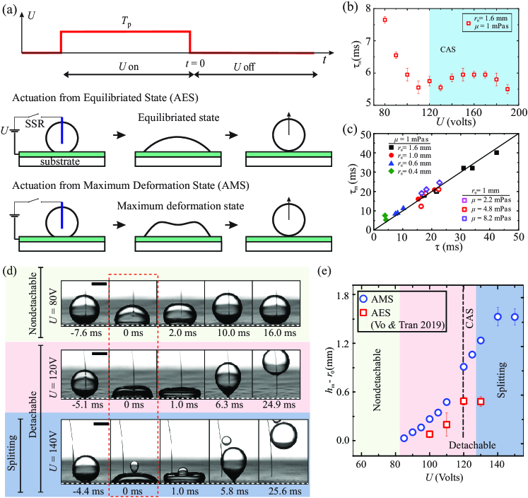
In practice, beside the applied voltage used to control the strength of the electrowetting effect, the activating duration of the voltage (see Fig. 1a, top panel) is also an important parameter determining jumping behaviours of the actuated droplets. Two major approaches to modulate to induce droplet jumping by electrowetting are actuation from equilibriated state (AES) and actuation from maximum deformation state (AMS). In the AES approach (Fig. 1a, middle panel), the activating duration is held until the droplet reaches its new equilibrium. In other words, is set , where is the time required for droplet to reach the new equilibrium after the electrowetting effect is activated (Cavalli et al., 2016; Vo & Tran, 2019; Wang et al., 2020). As is well-defined using system’s parameters (Vo et al., 2018), AES approach is simple and well-controlled. However, the ability to induce droplet jumping using the AES method is limited by contact angle saturation, i.e., the electrowetting effect saturates at high applied voltage (Mugele & Baret, 2005) resulting in a saturation of the excess surface energy supporting droplet detachment. In contrast, in the AMS approach (Fig. 1a, bottom panel), is set equal to , i.e., the time for droplet to reach maximum deformation state after the electrowetting effect is activated (Lee et al., 2012, 2014). As the excess surface energy at the maximum deformation state is higher than that at the equilibriated state, AMS is a more effective approach compared to AES. For instance, for the same actuating system, the critical voltage for droplet detachment to occur from AMS is lower than that from AES (Lee et al., 2014; Wang et al., 2017). As a result, AMS is a more favourable method in practical applications (Hong et al., 2015; Hong & Lee, 2015). Nevertheless, there is yet a parametric study on the dynamical behaviours of droplet detachment using AMS. Moreover, the critical conditions for droplet detachment using AMS is not yet established. This tremendously limits the applicability of the AMS method.
In this paper, we systematically investigate detachment behaviours of droplets under electrowetting actuation using AMS method by varying three control parameters: applied voltage , droplet’s viscosity , and droplet radius . We first confirm that AMS is a more effective approach to induce droplet detachment compared to AES shown by both lower critical detachment voltage and higher maximum jumping height. We then construct a comprehensive phase diagram separating detachable and nondetachable behaviours of droplets under AMS varying all the three control parameters. The dependence of detach velocity and detach time on the control parameters are also examined in details. Finally, we theoretically develop and experimentally verify a model describing the critical condition for droplet detachment using AMS approach.
2 Experimental method
2.1 Experimental setup and Materials
To induce the electrowetting effect, we use a substrate made from an indium-tin-oxide (ITO) glass slide spin-coated with a layer of fluoropolymer (Teflon-1601, DuPont) (Vo & Tran, 2021a). We set the thickness of the Teflon layer at to ensure electrical insulation for the ITO electrode. To apply a voltage between a droplet deposited on the substrate and the ITO electrode, we use an m diameter tungsten wire dipped into the droplet bulk and connect it to the positive terminal of a direct-current (DC) power supply via a normally open solid state relay (SSR) (see Fig. 1a). The negative terminal of the power supply is connected to the ITO electrode. We use a function generator to close the SSR, thereby applying a voltage in the range between the electrodes for a controlled duration (Fig. 1a) to induce the electrowetting effect and droplet jumping. For our electrowetting substrates, the voltage causing contact angle saturation is V (Tab. 1).
| %wt glycerol | (mPas) | () | () | (V) |
|---|---|---|---|---|
| 0 | 1.0 | 1000 | ||
| 20 | 2.2 | 1053 | ||
| 41.5 | 4.8 | 1106 | ||
| 55 | 8.2 | 1141 | ||
| 67 | 17.6 | 1174 | ||
| 74 | 32.7 | 1192 | ||
| 80 | 68.7 | 1210 |
We use aqueous glycerin solutions consisting of glycerol, DI water, and 0.125 M sodium chloride to generate droplets. The electrical conductivity of the working liquid is measure experimentally at . In our analysis and similar to other studies of electrowetting (Mugele & Baret, 2005; Baret & Brinkmann, 2006), we consider liquid droplets perfectly conductive and neglect the minute effect of varying liquid permittivity. The viscosity of glycerin solutions is varied from to by adjusting the glycerol concentration (Tab. 1). The droplet radius is also varied between and . We immerse the substrate in a pool of silicone oil; the oil’s temperature is kept at to maintain consistent experimental conditions. The use of silicone oil as the outer phase in our experiment is not only to reduce contact angle hysteresis but also to increase initial contact angle of liquid droplets on the substrates (Baret & Brinkmann, 2006; Hong & Lee, 2015). The contact angle of glycerin solution droplets deposited on the substrate in the silicone oils is in the absence of the electrowetting effect. For simplicity, the viscosity of the oil is kept fixed at . Other properties of the working liquids, including density and interfacial tension , are measured experimentally and given in Tab. 1.
To capture the behaviours of droplets under electrowetting actuation, we use a high speed camera (Photron, SAX2), typically running at 5000 frames per second (FPS). The recorded images are processed using MATLAB to extract the contact radius and dynamic contact angle during actuation, as well as the jumping height of droplets after actuation. The measurements of and , as well as the uncertainty analysis, follow the same experimental procedure described in our previous study (Vo & Tran, 2019). The uncertainty of contact angle measurements is estimated within . For each set of the control parameters (, , ), the experiment is repeated three times.
2.2 Electrowetting actuation
To induce jumping of droplets using electrowetting actuation, we note that the activating duration plays a crucial role. Experimental studies have pointed to the time to reach maximum deformation as the most optimal time duration for jumping droplets, i.e., causing highest jumping (Wang et al., 2017). We also note that the dynamics of droplets actuated by the electrowetting effect is either underdamped or overdamped, i.e., the electrowetting-induced driving force is opposed dominantly by either the droplet inertia or contact-line friction, respectively (Vo et al., 2018). Each one of these behaviours are characterised by a distinct spreading timescales. As it was shown that electrowetting-induced droplet detachment from solid substrates is only possible for spreading in the underdamped regime, we set the activating duration equal to the underdamped characteristic spreading time (Vo et al., 2018; Wang et al., 2020; Xiao & Wu, 2021):
| (1) |
where the electrowetting number , also known as the electrical capillary number (Hassan et al., 2023; Fallah & Fattahi, 2022), is defined as for and for . Here, and respectively are the dielectric constant and thickness of the Teflon coating, the permittivity of free space, the droplet density, the droplet-oil interfacial tension, and V the threshold voltage above which contact angle saturation (CAS) occurs. The threshold voltage is determined experimentally by examining the dependence of equilibrated contact angle on the applied voltage (Vo & Tran, 2021b). Slight fluctuation of is within V and occurs when varying the liquid’s viscosity (see Tab. 1). We note that Eq. 1 implies that also saturates when due to the contact angle saturation effect, consistent with the experimental data shown in Fig. 1b. In Fig. 1c, we show an excellent agreement between the measured values of the time to reach maximum deformation and the characteristic spreading time of droplets actuation in the underdamped regime. This strongly suggests that can be used to describe the time to reach maximum deformation of droplets under electrowetting actuation. As a result, the activating duration in our experiment is determined by Eq. 1, i.e., dependent only on the experimental parameters and free of uncertainty from the experimental values of .
3 Results and Discussions
3.1 Droplet jumping by EWOD actuation from maximum deformation state
In Fig. 1d, we show several series of snapshots of actuated droplets to illustrate their spreading and jumping dynamics. From the top panel to the bottom one, the applied voltage is increased from V to V, while the droplet radius and viscosity are fixed at mm, mPa s, respectively. Generally, we observe that as soon as the electrowetting effect is activated on a droplet, it causes droplet spreading with an initial contact-line velocity and generates on the droplet’s surface capillary waves propagating from the contact line toward the apex. At the end of the activating duration (), the droplet immediately recoils and subsequently jumps off from the substrate if the applied voltage is sufficiently high. For instance, in the experiment shown in Fig. 1d, droplet detachment from the solid substrate occurs for V. We also observe that at high applied voltages, e.g., V (Fig. 1d, last panel), a small satellite droplet is ejected from the actuated droplet. This is due to the effect of the strong capillary waves on the droplet’s surface generated by the electrowetting effect (Vo & Tran, 2021b).
In the cases that an actuated droplet detaches from the substrate, the detach time , measured from the time reference to the moment the droplet detaches, reduces with the applied voltage. For instance, drops from ms to ms when increases from 120 V to 140 V (Fig. 1d). Moreover, the maximum jumping height defined as the maximum height of the droplet’s center of mass increases with . For instance, significantly increases from mm to mm when increases from 100 V to 140 V (Fig. 1d). Comparing the maximum jumping height obtained in our experiment with the one obtained in the case jumping is induced by AES (Fig. 1e), we observe that for the same voltage, obtained from AMS (blue circles) is consistently higher than that from AES (red squares). Moreover, the maximum jumping height obtained from AMS is not limited by contact angle saturation, in contrast to that from AES.
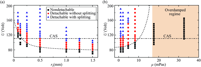
In Fig. 2, we show the phase diagrams of droplet behaviours obtained by varying three the control parameters , , and . These observed behaviours, which are illustrated in Fig. 1d, include nondetachable, detachable without splitting, and detachable with splitting. The critical voltage at the transition for detachment is higher for smaller droplet size (Fig. 2a) or higher viscosity (Fig. 2b). We also observe that the detachment of droplet is limited for as the transition from the underdamped regime to overdamped regime occurs at (Fig. 2b) (Vo et al., 2018). We highlight that AMS method works for as small as , a limit that was not possible using AES for the same substrate (Vo & Tran, 2019).
3.2 Detach velocity and detach time
In the case that a droplet detaches from the solid substrate, the detach velocity , defined as the droplet’s center-of-mass velocity at the moment it completely separates from the substrate, and the detach time , i.e., the duration from the reference time to the separating moment, are the most critical parameters representing the detaching dynamics. Understanding of these characteristic parameters help optimise design and operations of droplet-actuating systems using electrowetting effect. In this section, we discuss the dependences of and on the applied voltage , viscosity , and droplet radius .
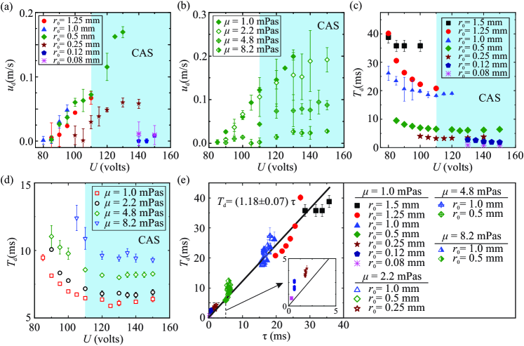
We first focus on the detach velocity . In Fig. 3a, we show the dependence of on the applied voltage for varying from 0.08 mm to 1.25 mm and fixed at . Generally, we observe that increases with as a result of higher electrical energy applied to the system. However, the dependence of on becomes more irregular at high applied voltage, i.e., V. For example, for mm, varies little between V and V. We attribute such irregular dependence of on to hydrodynamical and electrical instabilities of the system at high voltage. When the applied voltage increases, the electrical force applied to the contact line becomes larger, causing more abrupt and forceful deformation to the droplet, e.g., stronger capillary waves and even splitting of the droplet (Fig. 1d). Such violent behaviours induce nonlinear effects that reduce the energy transfer efficiency, from electrical to kinetic energy of the detached droplet. Moreover, electrical leakage may be possible through the dielectric layer at high applied voltage without breaking it down during the experiment (Moon et al., 2002). This also reduces the efficiency of the EWOD effect in generating higher for jumping droplets. Therefore, reducing irregularities at high voltage may require increasing viscosities of the liquids or using insulators with higher dielectric strength. Next, in Fig. 3b, we plot the dependence of on for varying from to and fixed at mm. We observe that for V, linearly increases with , whereas for V, approaches a plateau. The increasing rate of with also reduces with higher due to larger viscous dissipation.
We now examine the detach time . In Fig. 3c and d, we respectively show vs. for various droplet radii and droplet viscosities. We note that for mm and mm, the voltage is limited at 110 V and 100 V, respectively, due to frequent electrical breakdowns of the dielectric layer separating the electrode and the liquids. Here, electrical breakdowns increase with the actuation time, as well as the contact area between the droplet and the substrate during actuation. Both factors increase with larger droplet radius.
Typically, decreases with increasing as long as the voltage is within the contact angle saturation (CAS) limit, i.e., 110 V in our case. The detach time eventually reaches a plateau when the applied voltage exceeds . Here, we note that for AMS is defined the same way as the droplet’s retracting time, i.e., from the moment the electrowetting effect is turned off at the droplet’s maximum deformation to the moment the droplet detaches from the surface. In addition, the retracting time of the droplet only depends on its maximum spreading diameter, which is limited by CAS. As a result, we infer that also saturates when , consistent with our experimental results shown in Fig. 3c and d.
The detach time , which is measured from the moment the voltage is released to the detaching moment, is defined the same way as the retracting time of the droplets from maximum deformation. As a result, we hypothesise that is closely related to the timescale characterising the spreading (or retracting) dynamics of droplets. As the spreading droplets in our study are underdamped, we examine the relation between and the underdamped characteristic spreading timescale and show a plot of vs in Fig. 3e. The plot consists of data obtained by varying , , and in their explored ranges. We observe that the dependence of on can be approximately described using a linear relation , where , suggesting that is reasonably characterised by in the explored ranges of the control parameters. Furthermore, for each dataset obtained using fixed and , we note that Fig. 3c and Fig. 3d indicate that decreases with for and plateaus for . This implies smaller data deviation from the linear fit in Fig. 3e at higher voltages. In other words, the linear fit better describes the relation between and in the high-voltage regime.
3.3 Critical conditions for jumping droplets by EWOD actuation from maximum deformation state
We now seek for the critical condition for droplet detachment by AMS. We first note that the droplet actuation dynamics in our study is kept in the underdamped regime, as it is the requirement to enable detachment (Vo & Tran, 2019). This requirement also ensures that the excess surface energy at the maximum deformation state is not entirely dissipated by the viscous effect during retraction. Subsequently, we follow the energy balance approach used to determine the jumping conditions for droplets actuated by AES (Vo & Tran, 2019) to formulate the critical condition for droplets to detach from the solid substrate by AMS as
| (2) |
where is the difference between the surface energy at maximum deformation and the surface energy at the detach moment ; is the viscous dissipation and contact line elasticity energy during retraction. We note that the kinetic energy of a droplet vanishes at its maximum deformation state. The gravitational potential energy is negligible compared to the surface energy as the Bond number is small (). Here, is the density of silicone oil and is the gravitational acceleration.
We first focus on the surface energy difference and note that it can be written as , where is the surface energy at equilibriated state after applying the electrowetting effect without turning it off. On one hand, we note that the surface energy difference between the equilibrated state and detachment was already formulated (Vo & Tran, 2019): , where , are respectively the contact angle and contact radius of the droplet at the equilibriated state; is the contact angle of the droplet at the initial state. Moreover, we argue that the surface energy difference comes from the capillary wave generated at the beginning of droplet actuation; this wave would not occur if the voltage were to ramp up slowly to keep the spreading quasi-static. As a result, the surface energy difference is calculated by the energy carried by the capillary wave , where is the wave amplitude at time ; is the angular frequency of the wave; is the wavelength; is the decaying ratio of the capillary waves; is the contact line friction coefficient; is the area of a hypothetical spherical cap having contact angle and base radius ; and is the contact line Weber number, defined to directly relate to the applied voltage by the relation . Here, is the critical voltage for capillary wave generation on the droplet’s surface (Vo & Tran, 2021b). In our experiment, varies from V to V depending on the viscosity and radius of the actuated droplet. We therefore obtain the expression of the surface energy difference:
| (3) |
We note that the damping ratio is essentially similar to the Ohnesorge number Oh in which the contact line friction coefficient is used instead of the liquid’s viscosity to represent dissipation. In our analysis, is obtained empirically using the relation , where is a fitting parameter (Vo et al., 2018; Vo & Tran, 2019). By using instead of Oh, the dissipation in the liquid bulk is effectively neglected (Vo & Tran, 2019; Carlson et al., 2012a, b). Indeed, the ratio , calculated for all of our experiments, varies from to , strongly suggesting that the dissipation at the contact line is dominant. As a result, we ignore bulk dissipation in our estimation of to arrive at Eq. 3. Also, by only considering dissipation at the contact line, we obtain an expression for (Vo & Tran, 2019):
| (4) |
The contact line elasticity energy is the surface energy accumulation due to pinning and subsequent stretching of the liquid-oil interface at the vicinity of the contact line (Joanny & de Gennes, 1984; Vo & Tran, 2019) and is determined by a similar approach with Vo & Tran (2019):
| (5) |
Here, , where is the receding contact angle, and is the defect’s size. In our experiment, which was conducted using the same setup and materials with Vo & Tran (2019), and the average defect’s size is nm. The parameter only changes minutely within the explored droplet radius: for .
Subtituting Eqs. 3, 4, 5 into Eq. 2, the condition at the transition between nondetachable and detachable behaviours is
| (6) |
As shown in the previous sections, both the activation time and the detach time are well approximated by the underdamped characteristic spreading time . We therefore simplify Eq. 6 as
| (7) |
where , , and . We note that depends on the electrowetting number following the Young-Lippmann’s equation (Mugele & Baret, 2005).
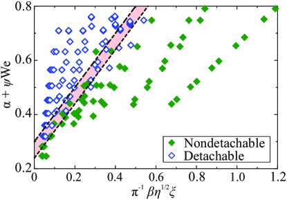
In Fig. 4, we show a plot of versus of all the data obtained for the nondetachable and detachable behaviours shown in Fig. 2. Here, the composite terms and respectively represent the driving energy and the energy cost for detachment. The shaded area indicates the transitional extent caused by variation in () resulted from variations in both the defect’s size and the radius . We note that all the terms in Eq. 7 are calculated using the system parameters except the contact line friction coefficient, which is determined empirically using with (Vo et al., 2018; Vo & Tran, 2019), and the receding contact angle determined independently from our previous work (Vo & Tran, 2019). The excellent agreement between the experimental data and the formulated jumping condition (Eq. 7) thus highlights our analysis as a predictive tool for utilizing modulated electrowetting in droplet actuation and detachment from surfaces.
4 Conclusions
We aim to systematically investigate droplet detachment induced by EWOD using actuation from maximum deformation state (AMS). By varying droplet radius, viscosity, and applied voltage, we demonstrate a significant expansion of the detachable regime for droplets actuated by using the electrowetting effect with AMS and provide a comprehensive phase diagram of the detachment behaviours. The applied voltage for AMS, no longer bounded by contact angle saturation limit, enables detachment of droplets as small as 80 m in radius. This introduces a powerful tool for applications requiring actuation and detachment of droplets from solid surfaces, in particular those dealing with small droplets or highly viscous liquids. We then provide a detailed characterisation of detach velocity and detach time of actuated droplets. Finally, we developed a theoretical prediction for the critical condition causing droplet detachment. The theoretical prediction is consistent with our experimental data for liquid viscosity ranging from 1 mPa to 68.7 mPa, droplet size from 0.08 mm to 1.5 mm, and applied voltage from 60 V to 200 V.
We note that our study is limited within the droplet-in-oil setting and further studies may be required to explore the limit of our analysis in the droplet-in-air setting, which is typically known for stronger hysteresis effect and electrical instability at the three-phase contact line. Nevertheless, our study may serve as a strong basis for wider use of electrowetting in applications requiring precise actuation of droplets such as tissue engineering, digital microfluidics, and 3D printing. Our results also provide key insights to mechanistic understanding of related phenomena such as coalescence-induced jumping of droplets (Boreyko & Chen, 2009; Farokhirad et al., 2015; Liu et al., 2014) or droplet bouncing on solid substrates (Sanjay et al., 2023).
Acknowledgments
This study is supported by Nanyang Technological University, the Republic of Singapore’s Ministry of Education (MOE, grant number MOE2018-T2-2-113), and the RIE2020 Industry Alignment Fund – Industry Collaboration Projects (IAF–ICP) Funding Initiative, as well as cash and in-kind contribution from the industry partner, HP Inc.
Declaration of Interests
The authors report no conflict of interest.
References
- Baret & Brinkmann (2006) Baret, Jean-Christophe & Brinkmann, Martin 2006 Wettability Control of Droplet Deposition and Detachment. Physical Review Letters 96 (14), 146106.
- Berge & Peseux (2000) Berge, B & Peseux, J 2000 Variable focal lens controlled by an external voltage: An application of electrowetting. The European Physical Journal E 3 (3), 159–163.
- Blossey (2003) Blossey, Ralf 2003 Self-cleaning surfaces — virtual realities. Nature Materials 2 (5), 301–306.
- Boreyko & Chen (2009) Boreyko, Jonathan B. & Chen, Chuan Hua 2009 Self-propelled dropwise condensate on superhydrophobic surfaces. Physical Review Letters 103 (18), 2–5.
- Carlson et al. (2012a) Carlson, A., Bellani, G. & Amberg, G. 2012a Contact line dissipation in short-time dynamic wetting. EPL (Europhysics Letters) 97 (4), 44004.
- Carlson et al. (2012b) Carlson, Andreas, Bellani, Gabriele & Amberg, Gustav 2012b Universality in dynamic wetting dominated by contact-line friction. Physical Review E 85 (4), 045302, arXiv: 1111.1214.
- Cavalli et al. (2016) Cavalli, Andrea, Preston, Daniel J., Tio, Evelyn, Martin, David W., Miljkovic, Nenad, Wang, Evelyn N., Blanchette, Francois & Bush, John W M 2016 Electrically induced drop detachment and ejection. Physics of Fluids 28 (2), 022101.
- Dey et al. (2019) Dey, Ranabir, Van Gorcum, Mathijs, Mugele, Frieder & Snoeijer, Jacco H. 2019 Soft electrowetting. Soft Matter 15 (32), 6469–6475.
- Fair et al. (2001) Fair, R.B., Pollack, M.G., Woo, R, Pamula, V.K., Hong, R, Zhang, T & Venkatraman, J 2001 A micro-watt metal-insulator-solution-transport (MIST) device for scalable digital bio-microfluidic systems. International Electron Devices Meeting. Technical Digest, , 00 (C), 16.4.1–16.4.4.
- Fair (2007) Fair, R. B. 2007 Digital microfluidics: is a true lab-on-a-chip possible? Microfluidics and Nanofluidics 3 (3), 245–281.
- Fallah & Fattahi (2022) Fallah, Keivan & Fattahi, Ehsan 2022 Splitting of droplet with different sizes inside a symmetric T-junction microchannel using an electric field. Scientific Reports 12 (1), 1–12.
- Farokhirad et al. (2015) Farokhirad, Samaneh, Morris, Jeffrey F. & Lee, Taehun 2015 Coalescence-induced jumping of droplet: Inertia and viscosity effects. Physics of Fluids 27 (10), 102102.
- Hao et al. (2014) Hao, Chonglei, Liu, Yahua, Chen, Xuemei, He, Yuncheng, Li, Qiusheng, Li, K Y & Wang, Zuankai 2014 Electrowetting on liquid-infused film (EWOLF): complete reversibility and controlled droplet oscillation suppression for fast optical imaging. Scientific Reports 4 (1), 6846.
- Hassan et al. (2023) Hassan, Rizwan Ul, Khalil, Shaheer Mohiuddin, Khan, Saeed Ahmed, Moon, Joonkyeong, Cho, Dae Hyun & Byun, Doyoung 2023 Electric field and viscous fluid polarity effects on capillary-driven flow dynamics between parallel plates. Heliyon 9 (6), e16395.
- He et al. (2021) He, Xiaodong, Zhang, Jianfeng, Yang, Bo, Zhang, Xiaoping & Deng, Youquan 2021 Droplet three-dimension manipulation in parallel liquid-infused membrane plates configuration. Sensors and Actuators, B: Chemical 330, 129344.
- Hong et al. (2014) Hong, Jiwoo, Kim, Young Kwon, Kang, Kwan Hyoung, Kim, Joonwon & Lee, Sang Joon 2014 Spreading dynamics and oil film entrapment of sessile drops submerged in oil driven by DC electrowetting. Sensors and Actuators, B: Chemical 196, 292–297.
- Hong et al. (2015) Hong, Jiwoo, Kim, Young Kwon, Won, Dong-Joon, Kim, Joonwon & Lee, Sang Joon 2015 Three-dimensional digital microfluidic manipulation of droplets in oil medium. Scientific Reports 5 (1), 10685.
- Hong & Lee (2015) Hong, Jiwoo & Lee, Sang Joon 2015 Detaching droplets in immiscible fluids from a solid substrate with the help of electrowetting. Lab on a chip 15 (3), 900–907.
- Joanny & de Gennes (1984) Joanny, J. F. & de Gennes, P. G. 1984 A model for contact angle hysteresis. The Journal of Chemical Physics 81 (1), 552–562.
- Lee et al. (2012) Lee, Seung Jun, Lee, Sanghyun & Kang, Kwan Hyoung 2012 Droplet jumping by electrowetting and its application to the three-dimensional digital microfluidics. Applied Physics Letters 100 (8), 081604.
- Kuiper & Hendriks (2004) Kuiper, S. & Hendriks, B. H W 2004 Variable-focus liquid lens for miniature cameras. Applied Physics Letters 85 (7), 1128–1130.
- Lee et al. (2019) Lee, Jeongmin, Park, Yuna & Chung, Sang Kug 2019 Multifunctional liquid lens for variable focus and aperture. Sensors and Actuators, A: Physical 287, 177–184.
- Lee et al. (2014) Lee, Seung Jun, Hong, Jiwoo, Kang, Kwan Hyoung, Kang, In Seok & Lee, Sang Joon 2014 Electrowetting-induced droplet detachment from hydrophobic surfaces. Langmuir 30 (7), 1805–1811.
- Leïchlé et al. (2007) Leïchlé, T., Tanguy, L. & Nicu, L. 2007 Electrowetting-assisted drop deposition for controlled spotting. Applied Physics Letters 91 (22), 224102.
- Liu et al. (2014) Liu, Fangjie, Ghigliotti, Giovanni, Feng, James J. & Chen, Chuan Hua 2014 Numerical simulations of self-propelled jumping upon drop coalescence on non-wetting surfaces. Journal of Fluid Mechanics 752, 39–65.
- Mishchenko et al. (2010) Mishchenko, Lidiya, Hatton, Benjamin, Bahadur, Vaibhav, Taylor, J. Ashley, Krupenkin, Tom & Aizenberg, Joanna 2010 Design of Ice-free Nanostructured Surfaces Based on Repulsion of Impacting Water Droplets. ACS Nano 4 (12), 7699–7707.
- Moon et al. (2002) Moon, Hyejin, Cho, Sung Kwon, Garrell, Robin L & Kim, Chang-Jin “CJ” 2002 Low voltage electrowetting-on-dielectric. Journal of Applied Physics 92 (7), 4080–4087.
- Moon et al. (2013) Moon, Jong Kyun, Jeong, Jaeki, Lee, Dongyun & Pak, Hyuk Kyu 2013 Electrical power generation by mechanically modulating electrical double layers. Nature Communications 4 (1), 1486–1487.
- Mugele & Baret (2005) Mugele, Frieder & Baret, Jean-Christophe 2005 Electrowetting: from basics to applications. Journal of Physics: Condensed Matter 17 (28), R705–R774.
- Nelson et al. (2011) Nelson, Wyatt C., Sen, Prosenjit & Kim, Chang Jin C.J. 2011 Dynamic contact angles and hysteresis under electrowetting-on-dielectric. Langmuir 27 (16), 10319–10326.
- Pollack et al. (2000) Pollack, Michael G., Fair, Richard B. & Shenderov, Alexander D. 2000 Electrowetting-based actuation of liquid droplets for microfluidic applications. Applied Physics Letters 77 (11), 1725–1726.
- Sanjay et al. (2023) Sanjay, Vatsal, Chantelot, Pierre & Lohse, Detlef 2023 When does an impacting drop stop bouncing? Journal of Fluid Mechanics 958, 1–20.
- Sawane et al. (2015) Sawane, Yogesh B., Datar, Suwarna, Ogale, Satishchandra B. & Banpurkar, Arun G. 2015 Hysteretic DC electrowetting by field-induced nano-structurations on polystyrene films. Soft Matter 11 (13), 2655–2664.
- Vahabi et al. (2018) Vahabi, Hamed, Wang, Wei, Mabry, Joseph M. & Kota, Arun K. 2018 Coalescence-induced jumping of droplets on superomniphobic surfaces with macrotexture. Science Advances 4 (11), 1–8.
- Vo et al. (2018) Vo, Quoc, Su, Haibin & Tran, Tuan 2018 Universal Transient Dynamics of Electrowetting Droplets. Scientific Reports 8 (1), 836.
- Vo & Tran (2018) Vo, Quoc & Tran, Tuan 2018 Contact line friction of electrowetting actuated viscous droplets. Physical Review E 97 (6), 063101.
- Vo & Tran (2019) Vo, Quoc & Tran, Tuan 2019 Critical Conditions for Jumping Droplets. Physical Review Letters 123 (2), 24502.
- Vo & Tran (2021a) Vo, Quoc & Tran, Tuan 2021a Droplet ejection by electrowetting actuation. Applied Physics Letters 118 (16), 161603.
- Vo & Tran (2021b) Vo, Quoc & Tran, Tuan 2021b Dynamics of droplets under electrowetting effect with voltages exceeding the contact angle saturation threshold. Journal of Fluid Mechanics 925, A19.
- Wang et al. (2020) Wang, Qinggong, Xu, Meng, Wang, Chao, Gu, Junping, Hu, Nan, Lyu, Junfu & Yao, Wei 2020 Actuation of a Nonconductive Droplet in an Aqueous Fluid by Reversed Electrowetting Effect. Langmuir 36 (28), 8152–8164.
- Wang et al. (2017) Wang, Zhantao, van den Ende, Dirk, Pit, Arjen, Lagraauw, Rudy, Wijnperlé, Daniël & Mugele, Frieder 2017 Jumping drops on hydrophobic surfaces, controlling energy transfer by timed electric actuation. Soft Matter 13 (28), 4856–4863.
- Weng et al. (2021) Weng, Ning, Wang, Qinggong, Gu, Junping, Li, Jindong, Wang, Chao & Yao, Wei 2021 The dynamics of droplet detachment in reversed electrowetting (REW). Colloids and Surfaces A: Physicochemical and Engineering Aspects 616 (104), 126303.
- Xiao & Wu (2021) Xiao, Ke & Wu, Chen Xu 2021 Curvature effect of electrowetting-induced droplet detachment. Journal of Applied Physics 129 (23), 234701.
- Xu et al. (2020) Xu, Wanghuai, Zheng, Huanxi, Liu, Yuan, Zhou, Xiaofeng, Zhang, Chao, Song, Yuxin, Deng, Xu, Leung, Michael, Yang, Zhengbao, Xu, Ronald X., Wang, Zhong Lin, Zeng, Xiao Cheng & Wang, Zuankai 2020 A droplet-based electricity generator with high instantaneous power density. Nature 578 (7795), 392-396.