Framework and Methodology for Verification of a Complex Scientific Simulation Software, Flash-X ††thanks: US DOE ASCR
Abstract
Computational science relies on scientific software as its primary instrument for scientific discovery. Therefore, similar to the use of other types of scientific instruments, correct software and the correct operation of the software is necessary for executing rigorous scientific investigations. Scientific software verification can be especially difficult, as users typically need to modify the software as part of a scientific study. Systematic methodologies for building test suites for scientific software are rare in the literature. Here, we describe a methodology that we have developed for Flash-X, a community simulation software for multiple scientific domains, that has composable components that can be permuted and combined in a multitude of ways to generate a wide range of applications. Ensuring sufficient code coverage by a test suite is particularly challenging due to this composability. Our methodology includes a consideration of trade-offs between meeting software quality goals, developer productivity, and meeting the scientific goals of the Flash-X user community.
Index Terms:
Verification, Methodology, Test suite, Scientific software, MultiphysicsI Introduction
Scientific processes continue to rely on software as an important tool for data acquisition, analysis, and discovery. Therefore, similar to the use of other types of scientific instruments, correct software and the correct operation of the software is necessary for executing rigorous scientific investigations. Although the lifecycles of software and hardware instruments differ significantly, both need rigorous maintenance and upgrades to remain useful. In particular, software upgrades are often incremental in nature and require seamless operation of testing and verification frameworks to allow flexibility while avoiding degradation.
Flash-X [9] is a multiscale, multiphysics scientific software package designed to simulate physical systems that are modeled using a combination of partial differential equations (PDEs), ordinary differential equations (ODEs), and a few other motifs (e.g., algebraic or tabulated equations of state, etc.). It is built with composable components that can be permuted and combined in a multitude of ways to generate a wide range of applications for domains such as astrophysics[12] and computational fluid dynamics [3]. Since the code is often being developed at the same time as it is being used for executing scientific simulations, ensuring correct functionality requires extensive regular testing that accounts for various modes of use with different interoperability constraints for different applications. Flash-X is not unique in this regard. Other multiphysics applications with varying degrees of composability face similar challenges. For Flash-X we have developed a framework and a methodology with accompanying tools that we believe will be useful to other applications facing similar challenges.
II Flash-X and Testing Requirements
While Flash-X has been described in detail in [9], we provide here a brief overview for completeness. The primary functionality of the code is to solve the Euler or Navier-Stokes equations for compressible and incompressible flows on a discretized mesh. The resolution of the mesh can be fixed to a uniform grid across the domain (UG) or be dynamically controlled with adaptive mesh refinement (AMR)[2], where different parts of the domain are potentially assigned different resolutions based on the evolving characteristics of the local physical solution. Source terms and equations of state can be added to either formulation. Several source terms, such as nuclear burning [16], are included in the distribution, and several others are expected to be added by the user community depending on their needs. The code includes solvers for hyperbolic, parabolic, and elliptic PDEs; ODE solvers for certain equations of state (EOS) and burning networks; as well as algebraic solvers for both EOS and source terms. A Lagrangian framework is built into the code that can manage particles in purely passive mode as tracers, or in active mode for particle-in-cell or N-body simulations. The code interfaces with math libraries such as PETSc [1] and Hypre [10] to solve linear systems if needed.
An important characteristic of Flash-X is that it does not build an executable out of the whole code. With the help of the configuration layer and assisted by code translation tools [4, 13, 5], each application assembles its desired code components. Therefore, each instance of an application compiles only a fraction of the code. A code component can be a code snippet from a function, a whole function, or a collection of functions, and it can have alternative implementations that can each serve a different purpose. Some are meant for different physical regimes or different fidelity requirements, while others are meant to account for different hardware architectures. Components can be self-describing by encoding metainformation about how they are to be used in the assembled application. The choice of the alternative implementation is determined by the configuration layer based upon the encoded metainformation and command-line instructions.
An application instance in Flash-X resides in a specialized code unit, Simulation, with a subunit SimulationMain containing different implementations for each specific problem represented by simulation-name, such as Sod, SNIa Double Detonation or Pool Boiling. Each simulation is said to be an alternative implementation of the unit’s API configured using components from source code, initial conditions, composition in terms of additional species (to support nuclear or chemical reaction networks), and any needed customizations (see [15] for more details). These components also become the basis for the testing infrastructure. Unit tests are cast as their own simulation-name with minimal dependencies.
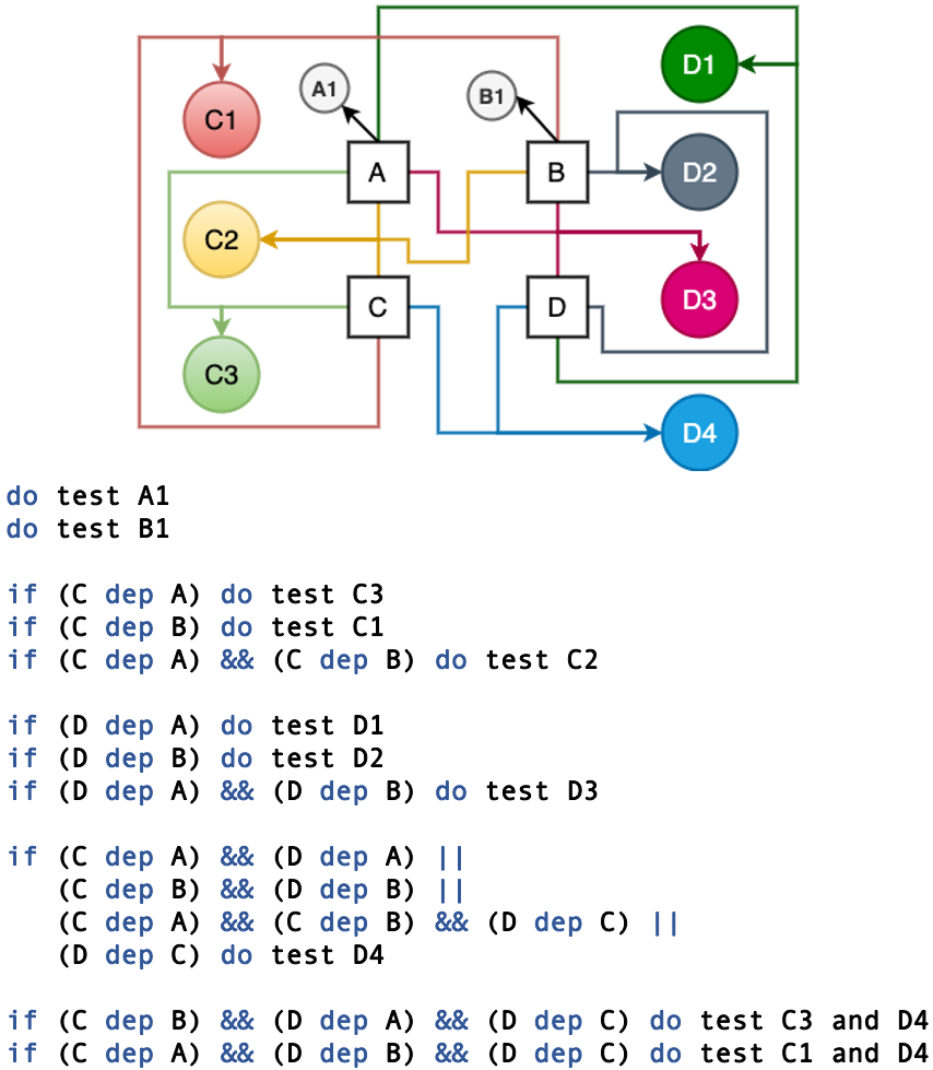
Few “pure” unit tests exist in the Flash-X test suite. Instead of testing each code component individually, the test suite is formulated in the form of scaffolding as explained in Figure 1. Here, if components A and B have unit tests A1 and B1, respectively, then a code unit C, which depends on A or B or a combination of the two, can be tested using one of the tests C1-C3 as outlined in the accompanying code snippet in the figure. A similar strategy is applied for the tests D1-D3 for a separate code unit D. However, if D depends on C and C depends on A and B, simply performing the test D4 along with A1, B1 and C2 will suffice. In this case C2 provides a scaffold for testing D.
For context, components A and B may represent a stenciled computation for the advection and diffusion terms of a PDE. These components are placed under the code unit Stencils, and are used by the units HeatAD (C) and IncompNS (D) to solve for heat transfer and incompressible fluid flow, respectively. A typical set of A1, B1 and C2 in this case involves testing the scalar transport of temperature through simple advection and diffusion problems. Test D4 includes testing the transport of heat flux in turbulent fluid flows using a fractional step solution of the incompressible Navier-Stokes equations. For this example, the tests involving components D are computationally expensive compared to the tests C1-C3, and therefore the scaffolding strategy enables the selection of tests to optimize the coverage versus execution time trade-off [7].
The regression tests described above can often be generated by carefully calibrating the runtime parameters of the existing application instances (see Section III-A). Typically, if a new component is added that does not have coverage from existing applications, it is required to also submit an application setup and a selection of parameters that can be used in a test configuration of the application in the pull request to be accepted.
Exhaustive coverage for testing all possible permutations and combinations of components in Flash-X is neither feasible nor desirable. Some combinations may be mathematically possible but physically impossible, while the requisite functionality check for some combinations may be adequately covered by others through the scaffolding described earlier. In the example above, the success of the test D4 makes A1, B1 and C2 redundant. However, for a quick diagnosis of the cause of failure, it is required that we build more tests than strictly necessary. Also, because the code is not stationary, it is prudent to build more tests when a code component is originally included in the source in case testing needs change due to changes in interoperability. Therefore, we have two requirements for the testing framework: (1) it should be possible for the contributors to specify the configuration and runtime parameters of each relevant application instance in the code repository as a possible test, and (2) the framework requires a mechanism to select tests from all those specified in the code repository in order to construct a particular test suite for execution on a particular platform with a particular software stack. In the next section, we describe how these elements of our testing methodology come together.
III Testing Framework
FLASH instituted regular regression testing before any standard testing frameworks were available for automating the process. Consequently, FlashTest [8] was developed in-house and served as a testing framework for FLASH, the predecessor of Flash-X. We find it to be the best option to run our test suite for Flash-X due to similarities in design and organization of the source code between the two. To inspect the results of the execution of the test suite, the accompanying web interface, FlashTestView, continues to be the most effective option. In the following, we describe what constitutes a test in Flash-X and how it fits into the testing framework.
III-A Components of a Test
The simulation-name configuration of the subunit Simulation/SimulationMain discussed above also contains a set of files with extension .par, referred to as parfiles, which provide values of the runtime parameters related to physics, dimensions, and coordinate system to be used in the application setup. An application is likely to have at least one .par file for each of the viable configurations it supports.
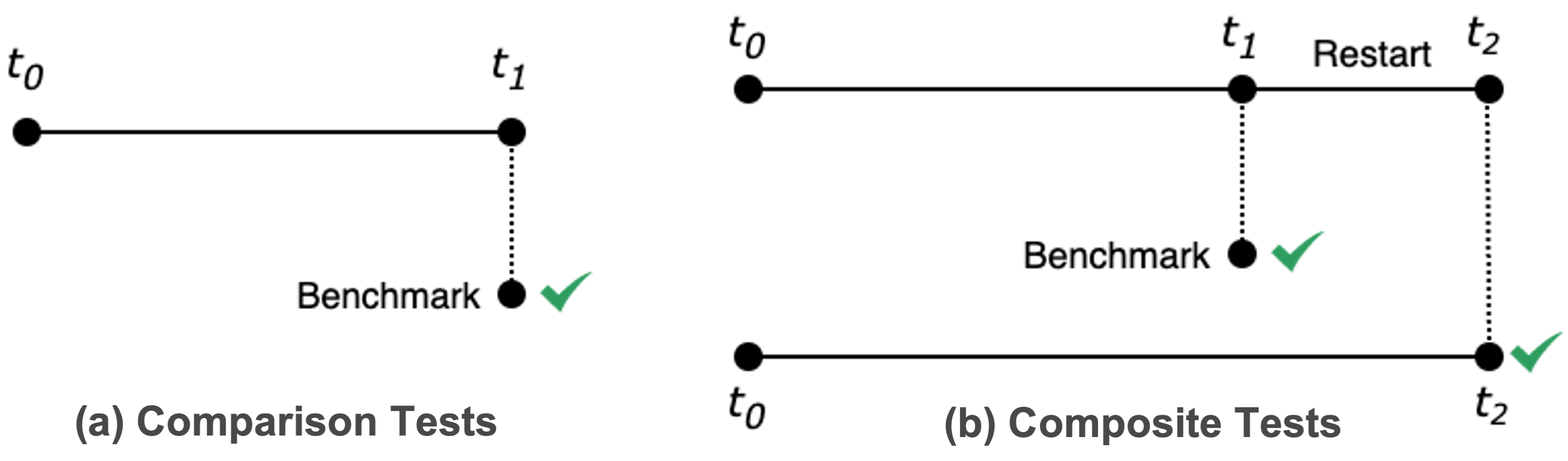
Flash-X’s test specifications are essentially a collection of options to be used to configure the applications for testing purposes along with an accompanying .par file. The options are specified during execution of Flash-X’s setup command, which also indicates which parfile to use. We support unit tests and regression tests. As discussed above, our unit tests do not strictly follow the definition as understood by the broader community. However, as expected, they do not rely on benchmarks. Regression tests are comparison or composite tests as shown in Fig 2. Comparison tests are based on the availability of an inspected and approved benchmark to compare the output generated by the application instance run as a test of correctness. Composite tests include two comparison tests, one in which the application starts from initial conditions and runs to a time and another in which the application starts from the checkpoint at time and runs to a time . Therefore, each composite test requires two benchmarks. Composite tests obviate the need for comparison tests on the corresponding application setups.
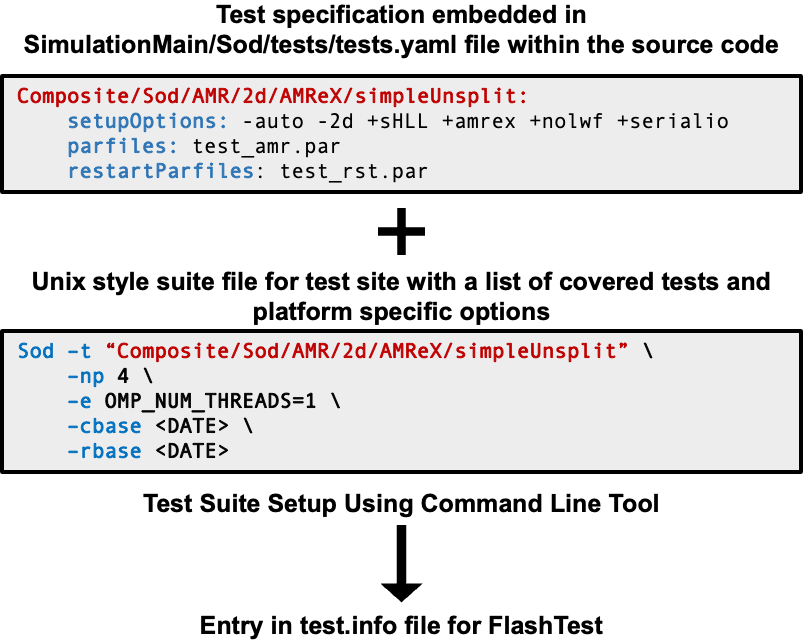
To satisfy the first testing framework requirement, all the information needed to configure a set of application instances as a set of related tests is encoded in a single tests.yaml file located under the associated simulation’s tests folder, along with the corresponding parfiles and preprocessing scripts associated with individual tests. To satisfy the second requirement of the testing framework, a single test suite dedicated to a particular platform and software stack can be constructed outside the code repository as a suite file by the Flash-X development team or, indeed, by any Flash-X user. The file contains an entry for each test to be included in the test suite, and each line includes additional site-specific information related to the test such as the location of the benchmarks and the number of processors to be used to run the test. Within the context of Flash-X, a site can be a personal workstation or a multinode cluster where users/developers wish to compile and run simulations. Each site is described by a Makefile.h that specifies the compiler, install location of external dependencies and various compile/link flags. Fig. 3 shows an example design of the test suite, which is described in the following subsections.
III-B Framework
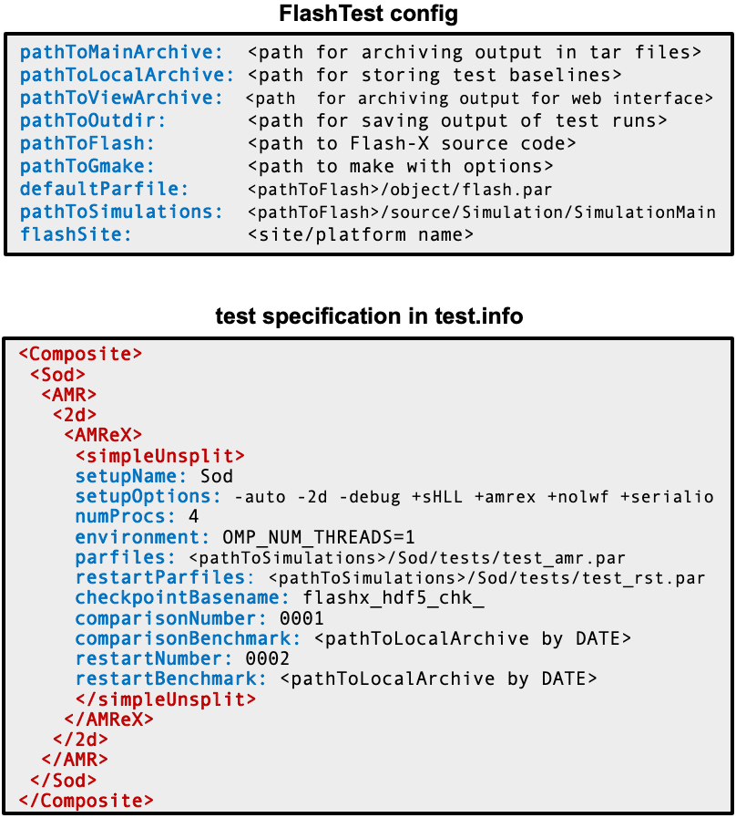
FlashTest reads complete test specifications that include site-specific details from an XML-format file called test.info. FlashTest also relies on other files to configure the execution of tests at a site. Details related to resource requirements, location of benchmarks, etc., are stored in a set of configuration files that are isolated from the source code and are under the control of the test executor. See Fig. 4 for an example of config and test.info files.
Originally, test.info files were written manually and independently for each site. This methodology was not particularly challenging when development was confined largely within one institution with infrequent external contributions. Reliance was placed on internal testing servers for regular testing needs. If at any point test specifications changed on any server, the changes were manually conveyed and resolved everywhere for consistency. External collaborators either did not run the test suite or independently configured their own infrastructure. While Flash-X initially followed the same methodology in its early development stages, we quickly realized that manual configuration and hidden internal test specifications are not compatible with the open development model we have now adopted for the code.
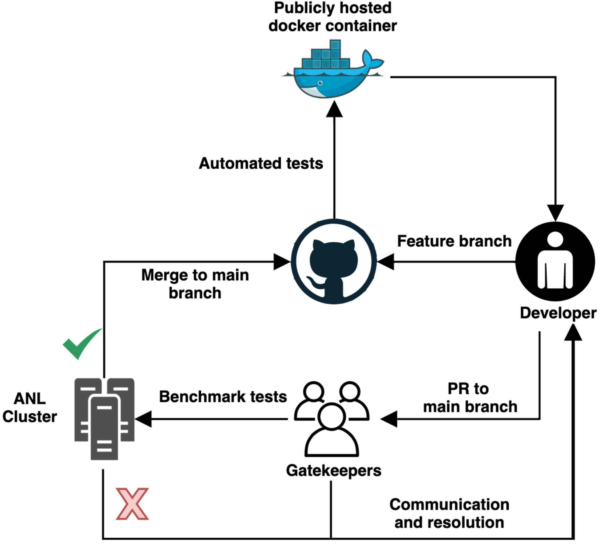
Flash-X has brought together developers from different scientific domains who require a more permissive testing infrastructure to manage modifications to test specifications at multiple testing sites. They need means to systematically setup configuration files on new sites, and a solution that avoids manual copy/paste tasks. As a result, the Flash-X testing infrastructure needed an evolution to balance the trade-offs between development and gatekeeping requirements (see Fig 6). Therefore, we built a tool that generates test.info from the information contained in the tests.yaml and suite files described above. The innovation of embedding an individual test specification within the Flash-X code repository where quality review of test specifications can be done along with source pull requests is also a direct consequence of this balancing act. We have also created a command-line toolkit that acts as a wrapper over FlashTest to (1) organize and implement uniform testing practices across multiple teams/platforms, and (2) automate the configuration of individual test suites so that developers can easily construct and customize test suites on their own development platform to suite their own development needs.
This is important since the natural interdependence between various code components and the number of different ways that code components can be configured often require that a developer modifying one particular component run multiple tests on their feature branch to confirm that modifications do not break other components. Compressible hydrodynamic solvers in Flash-X are good examples where such needs arise. Flash-X supports two interchangeable solvers with a third one planned for the near future. They can be configured with different number of state variables, which can become huge if a nuclear or a chemical reaction network is included. They support multiple coordinate systems such as Cartesian, cylindrical, spherical, and polar, and they can use many different reconstruction schemes. Any modification in how one solver interacts with the rest of the code can adversely affect the other. Therefore, a developer modifying either of the two solvers will need to run roughly a dozen or more tests on their feature branch regularly to ensure that nothing is broken. The toolkit makes it possible to configure a custom test suite on the feature branch running on a local platform in a matter of minutes.
III-C Stages of a Test
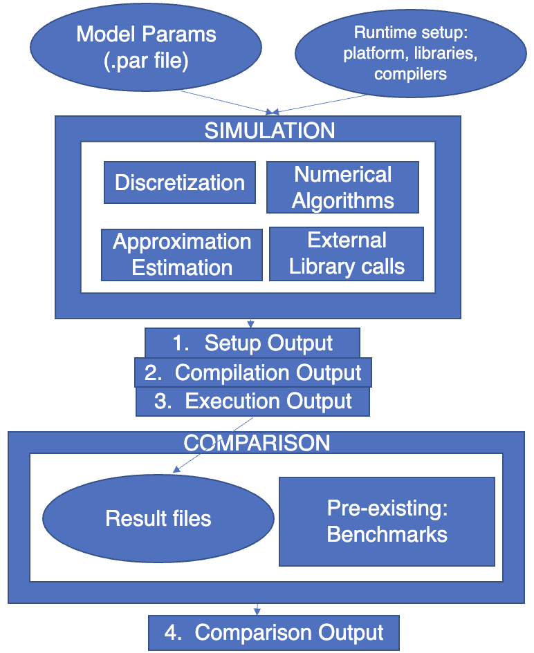
Testing of an application instance in Flash-X is performed in four different stages. Fig 5 outlines the workflow that FlashTest implements to assemble a test and identify errors during different stages as follows,
-
1.
Setup stage: During this stage Flash-X’s internal setuptool assembles an instance of the application for a test based on the setupOptions supplied in the tests.yaml file. This stage checks the internal design and organization of the source code.
-
2.
Compilation stage: Successful completion of the setup stage triggers compilation of the application. The compilation stage depends on the site-specific Makefile.h and checks for syntax errors in the source code, issues with compilation flags, and inability to link to external libraries.
-
3.
Execution stage: The execution stage tests the runtime performance of the code using potentially multiple MPI processes and confirms the successful execution of unit tests.
-
4.
Comparison stage: This stage compares the test execution output with a verified benchmark and reports success/failure based on spatial errors between two data sets. Error checks are performed using the Serial Flash Output Comparison Utility (SFOCU), which is a custom-designed command-line tool to compare Flash-X outputs.
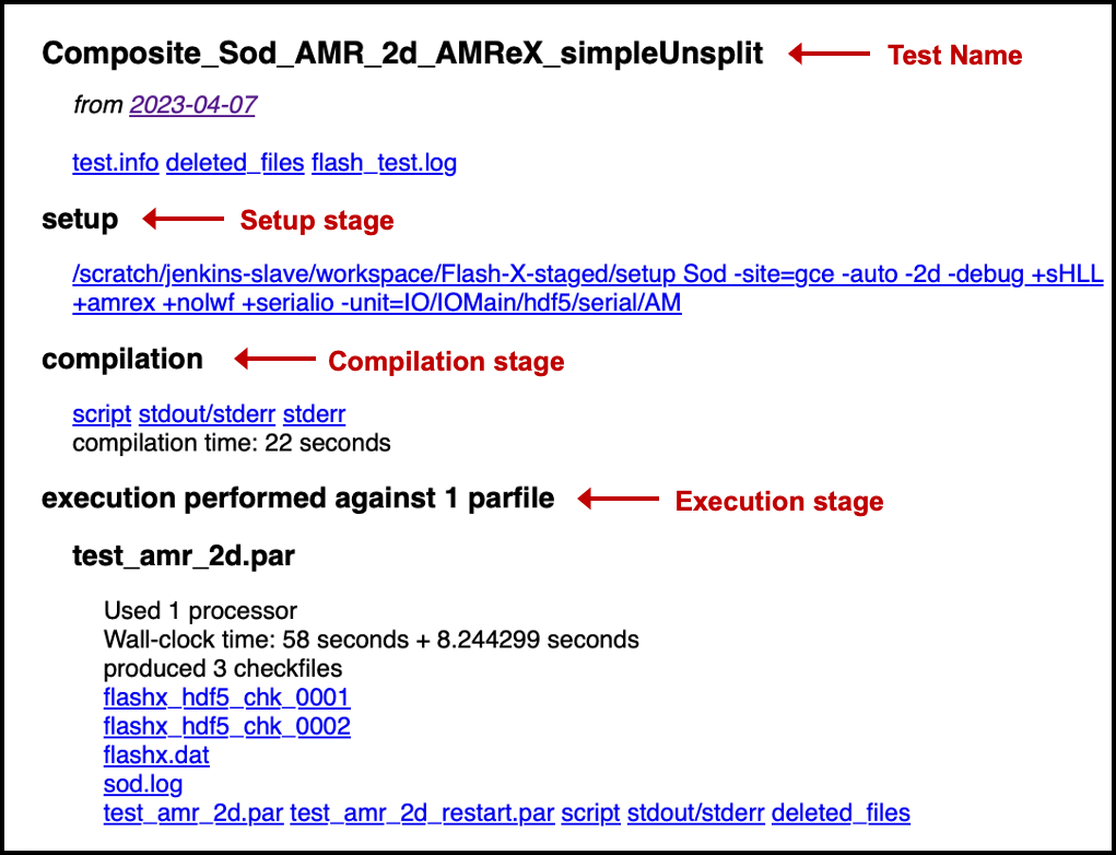
The results of the above stages can be viewed directly from the command line or using the FlashTestView web interface shown in Fig. 7. The interface presents all the test results with an interactive interface, making it easy to trace errors.
IV Tooling
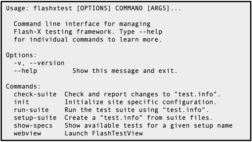
Fig 8 provides an overview of the command-line toolkit flashxtest, which wraps FlashTest and is distributed as a Python package. Installation is managed using pip, which enables systematic update and version tracking. Developers can use this tool to configure site-specific configuration files and manage their local testing infrastructure.
As described in section III-A the toolkit follows Flash-X’s design and organization philosophy to embed simulation-specific test configurations within their respective tests folders which contain relevant parfiles and yaml files. Developers can modify these files to add or update tests that accompany a change in source code. Simulation-specific tests.yaml files serve as a record of existing tests that can be used for different purposes.
A typical process of setting up the testing infrastructure using flashxtest is divided into three steps,
IV-A Initialization
During this step, a config file similar to that in Fig. 4 is created to specify the location of the Flash-X source code, site name, path to the archive and output directories to save test results, and compilation options that are not included in the site directory. This is achieved by running flashxtest init with relevant options [14]. The config file can be ephemeral, recreated during the invocation of every test run, or saved and version controlled depending on the site-specific test management.
IV-B Setting up a Suite
This step creates a test.info derived from a given suite file. Each entry in a suite file consists of commands in the style of Flash-X’s setuptool that specifies which test to run for a setup-name along with options for specifying the number of MPI processes, environment variables, and date of comparison (cbase) and restart (rbase) benchmarks following the style of Flash-X’s setuptool. The flashxtest setup-suite command creates test.info by combining information from tests.yaml and suite as shown in Fig 3. The suite files are typically managed by individuals/gatekeepers who own them, and therefore are not required to be exposed to the community. In the context of scientific software development, we refer to gatekeeping as a quality assurance practice that maintains an authoritative testing infrastructure under the guidance of the code management team and is managed by a designated group of gatekeepers.
In some cases, it may become necessary to create a new test.info file using an existing test.info as a seed file. The command setup-suite allows this by combining information from the seed.info, suite, and tests.yaml and determining priorities between conflicting attributes. This situation typically arises when seed.info undergoes an update through the web interface, where users/developers can update the benchmark information that leads to changes in values for the comparisonBenchmark and restartBenchmark shown in Fig. 4. The updated information in the seed.info file should take precedence over the entries in the suite and tests.yaml files, and communicated to developers and gatekeepers.
Changes in yaml files are discussed during pull requests, at which point the site specific test.info files should be updated. Changes can be manual or automated, depending on the level of control desired by developers/gatekeepers. For example, the process of accepting updates to yaml files is automated for our community testing site provided by the University of Tennessee. However, for the authoritative testing site at Argonne National Laboratory, updating test.info requires manual intervention after careful deliberation of differences compared to existing seed.info. Individual developers can operate in either mode.
IV-C Running a Suite
The final step is the flashtext run-suite command which runs FlashTest using the config and test.info files and reports the success or failure of each test. Results can be inspected through the web interface if it is installed, or through the logfile generated during the run. The results are also archived to appropriate locations during this step.
V TestSuite
For a component-based scientific code like Flash-X, ensuring adequate coverage in testing is very non-trivial. Different permutations and combinations of the code components result in different application instances needed by different science domains that use Flash-X [6, 11]. The application setups that are part of the Simulation unit are primarily designed to run simulations. The first challenge in devising a test is to determine parameters that will allow the simulation to run quickly while still exercising all the relevant features of the code that need to be exercised in order to confirm correctness. For example, if an application uses a custom refinement criterion for AMR, then the test must run long enough to refine at least once. Therefore, comparison and composite tests typically require the participation of domain scientists.
Once tests have been designed for all possible application instances, the next challenge is to select which of them to run regularly to ensure coverage. Running every available test is not practical, because the test suite would take too long. Moreover, unless an error is detected, running the entire set would waste resources. Therefore, the nominal set of tests that are run for every pull request are derived from the most complex applications. For example, the test for SNIa Double Detonation application exercises shock hydrodynamics, self gravity, nuclear burning with multiple species, and specialized equation of state. If this test passes, then there is no need to run any test that exercises a subset of these components in a similar way. However, there must be finer tests that test the code with simpler setups or at a lower level to help pinpoint the cause of error if a test such as SNIa Double Detonation fails. The test for cellular detonation exercises all the components that SNIa Double Detonation does, except self gravity. If that fails with the burning network used in SNIa Double Detonation, then the test can be run with a different burning network. If that also fails, then one of several hydrodynamics only tests is used. This methodology of repeatedly reducing the complexity of tests helps to quickly narrow down the cause of failure.
VI Conclusions
In this paper, we provide a methodology for testing and verifying complex scientific simulation software. The strategies we propose have been shaped by the requirements that arise when maintaining a very complex instrument for science and engineering workflows.
An open source development model requires implementation of gatekeeping practices to ensure research quality and reproducibility while balancing general community needs to streamline software development. Along with the design of our testing framework, we have also built a methodology to address the complexities of test coverage for highly composable systems like Flash-X, and the trade-offs between optimizing the performance of a testing suite and creating a system to rapidly and efficiently trace sources of failures.
We believe that the design and workflow of our customized testing tool flashxtest meets the current needs of the Flash-X community. We also believe that our solution can serve as a guide for designing testing frameworks for other scientific software systems where testing needs related to gatekeeping and general development are similar.
VII Acknowledgements
The submitted manuscript was created in part by UChicago Argonne, LLC, operator of Argonne National Laboratory (“Argonne”). Argonne, a U.S. Department of Energy Office of Science laboratory, is operated under Contract No. DE-AC02-06CH11357. The U.S. Government retains for itself, and others acting on its behalf, a paid-up nonexclusive, irrevocable worldwide license in said article to reproduce, prepare derivative works, distribute copies to the public, and perform publicly and display publicly, by or on behalf of the Government. The Department of Energy will provide public access to these results of federally sponsored research in accordance with the DOE Public Access Plan. http://energy.gov/downloads/doe-public-access-plan.
We also acknowledge the use of a large language model (LLM) to correct grammatical errors in the text.
References
- [1] S. Balay, S. Abhyankar, M. F. Adams, S. Benson, J. Brown, P. Brune, K. Buschelman, E. Constantinescu, L. Dalcin, A. Dener, V. Eijkhout, J. Faibussowitsch, W. D. Gropp, V. Hapla, T. Isaac, P. Jolivet, D. Karpeev, D. Kaushik, M. G. Knepley, F. Kong, S. Kruger, D. A. May, L. C. McInnes, R. T. Mills, L. Mitchell, T. Munson, J. E. Roman, K. Rupp, P. Sanan, J. Sarich, B. F. Smith, S. Zampini, H. Zhang, H. Zhang, and J. Zhang. PETSc/TAO Users Manual Revision 3.19. Technical Report ANL-21/39, Argonne National Laboratory, 2023.
- [2] M. J. Berger and P. Colella. Local adaptive mesh refinement for shock hydrodynamics. Journal of Computational Physics, 82(1):64–84, May 1989.
- [3] S. Chawdhary, A. Dhruv, A. Dubey, and E. Balaras. Immersed boundary methods for fluid-structure interaction problems in two-phase flows with phase changes. Bulletin of the American Physical Society, 63, 2018.
- [4] A. Dubey, K. Antypas, M. Ganapathy, L. Reid, K. Riley, D. Sheeler, A. Siegel, and K. Weide. Extensible component based architecture for FLASH, a massively parallel, multiphysics simulation code. Parallel Computing, 35:512–522, 2009.
- [5] A. Dubey and T. Klosterman. Language agnostic approach for unification of implementation variants for different computing devices. 2022. Proceedings of PPAM 2022.
- [6] A. Dubey, P. Tzeferacos, and D. Lamb. The dividends of investing in computational software design – a case study. International Journal of High Performance Computing Applications, 2018.
- [7] A. Dubey and H. Wan. Methodology for building granular testing in multicomponent scientific software. In 2018 IEEE/ACM 13th International Workshop on Software Engineering for Science (SE4Science), pages 9–15. IEEE, 2018.
- [8] A. Dubey, K. Weide, D. Lee, J. Bachan, C. Daley, S. Olofin, N. Taylor, P. M. Rich, and L. B. Reid. Ongoing verification of a multiphysics community code: Flash. Software: Practice and Experience, 45(2):233–244, 2015.
- [9] A. Dubey, K. Weide, J. O’Neal, A. Dhruv, S. Couch, J. A. Harris, T. Klosterman, R. Jain, J. Rudi, B. Messer, et al. Flash-X: A multiphysics simulation software instrument. SoftwareX, 19:101168, 2022.
- [10] R. Falgout and U. Yang. hypre: A library of high performance preconditioners. Computational Science-ICCS 2002, pages 632–641, 2002.
- [11] A. Grannan, K. Sood, B. Norris, and A. Dubey. Understanding the landscape of scientific software used on high-performance computing platforms. accepted, International Journal of High Performance Computing Applications, 2019.
- [12] J. A. Harris, R. Chu, S. M. Couch, A. Dubey, E. Endeve, A. Georgiadou, R. Jain, D. Kasen, M. P. Laiu, O. B. Messer, et al. Exascale models of stellar explosions: Quintessential multi-physics simulation. The International Journal of High Performance Computing Applications, 36(1):59–77, 2022.
- [13] J. Rudi, J. O’Neal, M. Wahib, and A. Dubey. CodeFlow: A code generation system for Flash-X orchestration runtime. Technical Report ANL-21/17, Argonne National Laboratory, Lemont, IL, 2021.
- [14] The Flash X Team. Flash-X Testing Tool. https://github.com/Flash-X/Flash-X-Test/tree/main/FlashXTest/example, 2023.
- [15] The Flash X Team. Flash-X Userguide. https://flash-x.github.io/Flash-X-docs, 2023.
- [16] F. Timmes. Integration of nuclear reaction networks. The Astrophysical Journal Supplement Series, 124:241–263, 1999.