Anti-Jamming Precoding Against Disco Intelligent Reflecting Surfaces Based Fully-Passive Jamming Attacks
Abstract
Emerging intelligent reflecting surfaces (IRSs) significantly improve system performance, but also pose a huge risk for physical layer security. Existing works have illustrated that a disco IRS (DIRS), i.e., an illegitimate IRS with random time-varying reflection properties (like a “disco ball”), can be employed by an attacker to actively age the channels of legitimate users (LUs). Such active channel aging (ACA) generated by the DIRS can be employed to jam multi-user multiple-input single-output (MU-MISO) systems without relying on either jamming power or LU channel state information (CSI). To address the significant threats posed by DIRS-based fully-passive jammers (FPJs), an anti-jamming precoder is proposed that requires only the statistical characteristics of the DIRS-based ACA channels instead of their CSI. The statistical characteristics of DIRS-jammed channels are first derived, and then the anti-jamming precoder is derived based on the statistical characteristics. Furthermore, we prove that the anti-jamming precoder can achieve the maximum signal-to-jamming-plus-noise ratio (SJNR). To acquire the ACA statistics without changing the system architecture or cooperating with the illegitimate DIRS, we design a data frame structure that the legitimate access point (AP) can use to estimate the statistical characteristics. During the designed data frame, the LUs only need to feed back their received power to the legitimate AP when they detect jamming attacks. Numerical results are also presented to evaluate the effectiveness of the proposed anti-jamming precoder against the DIRS-based FPJs and the feasibility of the designed data frame used by the legitimate AP to estimate the statistical characteristics.
Index Terms:
Physical layer security, jamming suppression, intelligent reflecting surface, transmit precoding, channel aging.I Introduction
Due to the broadcast and superposition properties of wireless channels, wireless communications are vulnerable to malicious attacks such as eavesdropping and jamming [2, 3, 4, 5]. To protect legitimate users (LUs) from eavesdropping, cryptographic techniques are used to prevent eavesdroppers from intercepting transmitted signals [2, 3]. Cryptographic techniques for secure communications rely on the computational difficulty of the underlying mathematical process required to break the codes. Therefore, the eavesdroppers can only effectively receive the transmit signals if they have extensive computational capabilities [6].
On the other hand, jamming attacks (also referred to as DoS-type attacks) can be launched by an active jammer (AJ) that imposes intentional interference on the communication between the legitimate access point (AP) and its LUs [4]. In practice, physical-layer AJs can generally be classified into constant AJs, intermittent AJs, reactive AJs, and adaptive AJs [3]. A constant AJ continuously broadcasts jamming signals, such as modulated Gaussian waveforms or pseudorandom noise, over an open wireless channel to prevent LUs from communicating with the legitimate AP. However, constant AJs are energy-inefficient because they constantly consume power, and thus energy constraints are an inherent drawback for AJs [7]. To overcome this drawback, intermittent AJs [8], reactive AJs [9], and adaptive AJs [10] have been investigated. The basic idea of these AJs is to reduce the duration of the jamming transmission in order to reduce the consumption of power. However, all types of active jamming require a certain amount of jamming power to effectively attack the LUs. Given the inherent energy disadvantage of AJs, can jamming attacks be launched without jamming power?
Recently, intelligent reflecting surfaces (IRSs) have been considered to be a promising technology for future 6G systems, and can be used to reflect electromagnetic waves in a controlled manner [11, 12]. Specifically, an IRS is an ultra-thin surface equipped with multiple sub-wavelength reflecting elements whose electromagnetic responses (i.e., amplitudes and phase shifts) can be controlled, for instance, by simple programmable PIN or varactor diodes [13]. Previous works have mainly focused on the use of legitimate IRSs in order to improve performance metrics such as spectrum efficiency (SE) [14, 15, 16], energy efficiency (EE) [17], cell coverage [18], or physical-layer security [19, 20], assuming the legitimate AP knows the the IRS-related channel state information (CSI), and can control their phase response. The authors of [16, 18] significantly enhanced the coverage and spectrum efficiency via the practical design of reconfigurable surfaces.
However, the emergence of IRSs also poses serious potential threats to wireless networks. Some works have pointed out that illegitimate IRSs can have a significant impact on wireless networks because the illegitimate IRSs [21, 22, 23, 24] are difficult to detect due to their passive nature. For example, the authors in [25] have reported an adversarial IRS-based passive jammer that essentially consumes no jamming power and that can destructively add the signal reflected from it with the direct path signal to minimize the received power at the LU, i.e., the signal-to-noise ratio (SNR). Although this passive jammer can launch jamming attacks without jamming power, the CSI of all wireless channels must be known at the unauthorized IRS. Due to the passive nature of IRSs, the CSI of IRS-aided channels is estimated jointly with that of the legitimate AP and LUs. Specifically, by exploiting the channel reciprocity of time division duplex (TDD) channels, the LUs instead of the legitimate IRS send pilot signals to the AP, and the AP then estimates the IRS-aided channels using methods such as the least squares (LS) algorithm [26]. If the illegitimate IRS aims to acquire LU CSI, it must train to learn CSI jointly with the legitimate AP and LUs. As a result, the assumption that the illegitimate IRS knows the CSI [25] is unrealistic for practical wireless networks.
Considering the difficulty of illegitimate IRSs to acquire CSI, can jamming attacks be launched without either jamming power or LU CSI? An interesting fully-passive jammer (FPJ) [27, 28] has been proposed to launch jamming attacks on LUs with neither LU CSI nor jamming power, where an illegitimate IRS with random phase shifts, referred to as a “disco” IRS (DIRS), is used to actively age the LUs’ channels. This causes serious active channel aging (ACA) interference, which is a type of inter-user interference (IUI). Specifically, the DIRS controller in [27] randomly generates a reflecting vector once during the reverse pilot transmission (RPT) phase. Then, during the subsequent data transmission (DT) phase, the DIRS controller randomly generates another reflecting vector. In [28], the authors further illustrated that the DIRS-based ACA interference can also be introduced by turning off the illegitimate IRS during the RPT phase and then randomly generating reflecting vectors multiple times during the DT phase. Such a temporal DIRS-based FPJ must know when the RPT phase ends and the DT phase begins, which requires some synchronization. These DIRS-based FPJs impose significant risks to PLS since they are difficult to detect due to their passive nature. It is worth noting that the adversarial IRSs studied in [27, 28] address a problem that is different from that in [29], where an adversarial IRS is employed to launch pilot contamination attacks to improve the eavesdropping capability of Eve. Moreover, these different RIS-based attack strategies are summarized in Table I.
| Reference | [25] | [23, 24, 27, 28] | [29] |
|---|---|---|---|
| Attack type | Jamming | Jamming | Eavesdropping |
| Transmit energy | Not required | Not required | Not required |
| Channel knowledge | Required | Not required | Not required |
| Mechanism | Optimize RIS reflecting | Generate time-varying | Reflect pilots by RIS to |
| vector to minimize SNR | RIS reflecting vectors | enhance eavesdropping |
In conventional wireless networks, classical anti-jamming approaches [4] such as spread spectrum and frequency-hopping techniques have been widely used to suppress jamming attacks. Spread spectrum refers to spreading the signal energy over a wider range of frequencies than the minimum required for transmission. In addition, frequency hopping is a technique used in spread spectrum communications in which the carrier frequency is rapidly changed in a pattern known to both the transmitter and receiver. However, classical anti-jamming approaches such as these can not be used against an FPJ since the source of the jamming attacks launched by the FPJs comes from the legitimate AP transmit signals themselves, which have the same characteristics (e.g., carrier frequency) as the transmit signals.
In addition, the ACA interference from the DIRS-based FPJs cannot be mitigated using multi-input multi-output (MIMO) interference cancellation [30, 31]. MIMO interference cancellation is effective for DIRS-based ACA interference only if the channel information of both the LU and DIRS-jammed channels is known by the legitimate AP [30, 31]. However, the DIRS phase shifts and amplitudes are randomly generated [27, 28]. It has been shown in [28] that a DIRS-based FPJ using only one-bit quantized phase shifts can achieve the desired jamming effect as long as the number of DIRS elements is sufficiently large. The key advantage of these approaches is that there is no effective anti-jamming approach available to counteract these destructive jamming attacks imposed by DIRS-based FPJs [27, 28].
To respond to the significant risks posed by illegitimate IRSs, an anti-jamming precoder is proposed in this paper for attacks launched by DIRS-based FPJs, which only requires the statistical characteristics of the DIRS-based ACA channels instead of their instantaneous CSI. The main contributions are summarized as follows:
-
•
A practical IRS model is considered, where the phase shifts of the DIRS reflecting elements are discrete and the amplitudes are a function of their corresponding phase shifts. Based on this practical IRS model, we describe a persistent DIRS-based FPJ that initiates jamming attacks through DIRS-based ACA interference and requires no additional jamming power or knowledge of the LU CSI, where the DIRS phase shifts are randomly generated once during the RPT phase and then randomly generated multiple times during the DT phase. Compared to [1, 28], the persistent DIRS-based FPJ mode111The DIRS controller for the case considered in [28, 1] generates a zero reflecting vector (i.e., the wireless signals are perfectly absorbed by the DIRS) during the RPT phase. Therefore, we refer to the approach studied here as persistent DIRS-based FPJ. is more harmful because it is not necessary to be synchronized with the training process of the legitimate system. Therefore, the developed anti-jamming precoder is more comprehensive. Moreover, the persistent DIRS-based FPJ based on the practical IRS model has different properties compared to [27, 28], for instance, the distribution of the random DIRS phase shifts affects the jamming impact of the persistent DIRS-based FPJ.
-
•
To address the serious threats posed by DIRS-based FPJs, we develop an anti-jamming precoder that requires only the statistical characteristics of the DIRS-based ACA channels and avoids requiring their instantaneous CSI, which is impractical to obtain. First, we derive the statistical characteristics of the DIRS-based ACA channels for both the persistent DIRS-based FPJ and the temporal DIRS-based FPJ [28, 1]. Based on the derived characteristics, we explain the difference between the jamming impact of the two methods. Second, we develop an anti-jamming precoder based only on the statistical characteristics, and prove that this precoder can achieve the maximum signal-to-jamming-plus-noise ratio (SJNR). The proposed anti-jamming strategy works for both the persistent DIRS-based FPJ and the related DISCO approaches in [27, 28].
-
•
For practical applications, it is necessary for the legitimate AP to acquire the ACA statistical characteristics without changing the system architecture or cooperating with the illegitimate DIRS. To this end, we design a data frame structure that the legitimate AP can use to estimate the statistical characteristics. Specifically, the LUs only need to feed back their received power to the legitimate AP when they detect that jamming is present. This requires little overhead because the received power values of the LUs are scalars and only a few feedback transmissions are sufficient to effectively estimate the statistical characteristics.
The rest of this paper is organized as follows. In Section II, we present the downlink of an MU-MISO system jammed by a persistent DIRS-based FPJ and define the SJNR optimization metric to quantify the anti-jamming effect. In addition, some useful results on matrix analysis and random variables are reviewed. In Section III, the statistical characteristics of the DIRS-based ACA channels are derived for the persistent DIRS-based FPJ and the earlier approach in [28, 1]. Then, an anti-jamming precoder is designed based on the derived statistical characteristics, and we prove that this precoder can achieve the maximum SJNR. In Section III-B, we develop a data frame structure the legitimate AP can use to estimate the statistical characteristics and we explain the mechanism by which it works. Finally, conclusions are given in Section IV, where the difference between the persistent DIRS-based FPJ and the version in [28, 1] is compared and discussed in detail.
Notation: We employ bold capital letters for a matrix, e.g., , lowercase bold letters for a vector, e.g., , and italic letters for a scalar, e.g., . The superscripts , , and represent the inversion, the transpose, and the Hermitian transpose, respectively, and the symbols and represent the Frobenius norm and the absolute value, respectively.
II System Description
In Section II-A, based on a practical IRS model, we illustrate the downlink of an MU-MISO system jammed by a persistent DIRS-based FPJ. Then, we define the SJNR optimization metric to quantify the system performance under this persistent DIRS-based FPJ. In Section II-B, the wireless channels involved are modelled based on near-field and far-field models, as appropriate. In Section II-C, some important results on matrix analysis and random variables are reviewed, which will be useful for the anti-jamming precoding derived in Section III.
II-A MU-MISO Systems Jammed by DIRS-based Fully-Passive Jammers
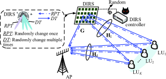
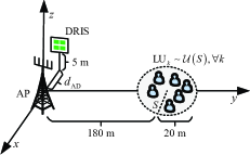
Fig. 1 schematically shows the general downlink model of an MU-MISO system that is jammed by the persistent DIRS-based FPJ. A legitimate AP uses antennas to communicate with single-antenna legitimate users denoted by LU1, , LUK. Meanwhile, a DIRS with reflecting elements is employed to launch fully-passive jamming attacks on the LUs. In many existing IRS-enhanced systems, it is assumed that the IRSs are placed close to the users to maximize a certain performance metric [17, 14, 15, 32, 18]. However, the assumption that the illegitimate DIRS has no information about the LUs, such as the LUs’ locations, is more realistic in the jamming scenario [27, 28, 1]. Therefore, the DIRS is assumed to be deployed close to the legitimate AP to maximize the impact of the DIRS [32].
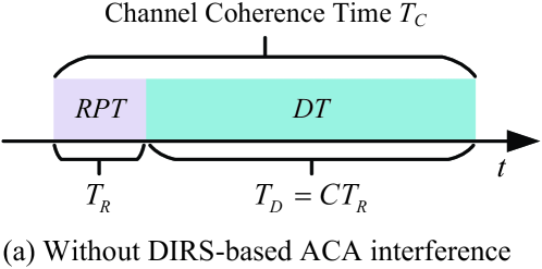
Disco Intelligent Reflecting Surfaces: In general, in the downlink of an MU-MISO system, the legitimate AP jointly trains the CSI with the LUs during the RPT phase, and the legitimate AP then designs a precoder that is used to transmit signals to the LUs during the DT phase. As shown in Fig. 2(a), the channel coherence time consists of two phases, i.e., the RPT phase and the DT phase, and the DT phase generally lasts much longer than the RPT phase. We assume that the length of the RPT phase is and that of the DT phase is for some integer . Since existing MU-MISO systems assume that the wireless channels remain unchanged during the channel coherence time, the designed precoder, such as the widely-used zero-forcing (ZF) precoder [33], can achieve good performance. However, the works in [27, 28] have shown that an attacker can exploit the ability of the IRS to controllably change the wireless channels to launch jamming attacks with neither jamming power nor LU CSI.
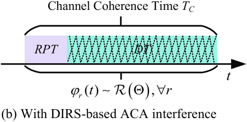
Unlike the temporal DIRS-based FPJ presented in [1, 28], the fully-passive jamming attacks can also be launched by randomly changing the DIRS reflection coefficients once in the RPT phase and multiple times in the DT phase, as depicted in Fig. 2(b). When the DIRS controller detects that the MU-MISO system begins to communicate, it controls the DIRS reflection properties to change randomly. The period during which the DIRS reflection coefficients are changing is about the same as the length of the RPT phase, i.e., . Therefore, during each DT phase, the first random change in the DIRS reflection coefficients starts at the same time as the DT phase. It is worth noting that the basic idea of DIRSs is to rapidly age the CSI during the channel coherence time instead of preventing the legitimate AP from obtaining it. As a result, signals transmitted to LUs during the DT phase will be jammed by the persistent DIRS-based FPJ.
Compared to the temporal DIRS-based FPJ in [1, 28], the proposed persistent DIRS-based FPJ does not require synchronization. In practice, it is difficult for an illegitimate DIRS to access information about the training synchronization of the legitimate MU-MISO system. Moreover, the difference between the jamming impact of the temporal DIRS-based FPJ in [1, 28] and that of the persistent DIRS-based FPJ shown in Fig. 2 (b) is quantified based on the theoretical derivation in Section III-A. The ACA from both the persistent DIRS-based FPJ and the temporal DIRS-based FPJ [1, 28] is different from the channel aging (CA) in a traditional MU-MISO system, which is caused by time variations in the RF propagation and delays in computation between the time the channels are learned at the legitimate AP and when they are used for precoding [34]. This type of CA can not be actively introduced and controlled.
In practice, an IRS is an ultra-thin surface equipped with multiple sub-wavelength reflecting elements whose phase shifts and amplitudes can be controlled by simple programmable PIN or varactor diodes [13]. We will assume the use of PIN diodes, whose ON/OFF behavior only allows for the creation of discrete phase shifts. In addition, due to the properties of the IRS, the amplitudes of the reflecting elements are a function of their corresponding phase shifts [11]. In particular, assume that the DIRS has -bit quantized phase shifts whose values can be chosen from the set , then the time-varying DIRS reflecting vector is given by
| (1) |
where the phase shift of the -th DIRS reflecting element is randomly selected from the possible phase shift set , i.e., . The probability of the phase shift taking the -th value of is represented by , i.e., and . Furthermore, the corresponding gain value is a function of and denoted by . We further denote all possible gain values by .
The work in [28] has shown that the jamming impact of a temporal DIRS-based FPJ does not depend on how the discrete random DIRS phase shifts are distributed when the element gains of the DIRS are assumed to be the same, i.e., the constant-amplitude assumption. However, we will show in the following section that this conclusion no longer holds when the gains of the DIRS reflecting elements are different.
Reverse Pilot Transmission And Linear Precoder Design: As mentioned above, the LUs’ CSI is obtained in the RPT phase through joint training with the LUs in order for the AP to design a precoder that is used to transmit LU signals during the DT phase [35]. Specifically, the pilot signal transmitted by LUk is denoted by . During the RPT phase, the received pilot vector at the AP is
| (2) |
where is the transmit power of , denotes the channel between the DIRS and LUk, denotes the channel between the DIRS and the AP, and denotes the direct channel between the AP and LUk. In addition, denotes additive white Gaussian noise (AWGN) at the AP that consists of independent and identically distributed (i.i.d.) elements with zero mean and variance , i.e., , . For ease of presentation, we denote the DIRS-jammed channel between the AP and LUk by , where represents the DIRS passive beamforming during the RPT phase. The DIRS passive beamforming remains unchanged during the RPT phase in a channel coherence interval, but changes during the RPT phases belonging to different channel coherence intervals. The overall DIRS-LU channel and the overall direct channel are represented by and , respectively.
In IRS-aided systems, the AP controls the legitimate IRS, and thus the IRS-aided and direct channels can be estimated [26]. However, in the jamming scenario investigated here and in the literature [27, 28], the DIRSs are controlled by a malicious adversary. Therefore, the AP can only estimate the combined channel according to the received pilot vector . Similarly, the combined channels between the AP and all LUs can be obtained in the phase. The overall combined channel is written as , and knowledge of can be obtained by the legitimate AP because the random DIRS reflection coefficients are constant during the RPT phase. Herein, we assume that the CSI of can be obtained by the AP during the phase [36], as imperfect CSI is not a primary concern in the jamming scenario, and its impact has also been thoroughly studied [37, 38, 39].
According to the obtained , the AP then designs a precoder that is used to transmit signals to the LUs during the phase. In general, the aim of an MU-MISO system is to maximize desired signals and minimize IUI. A widely-used linear precoder that can achieve zero IUI is the zero-forcing (ZF) algorithm [33]. Specifically, based on , the ZF precoder used at the AP can be computed by
| (3) |
where is the power allocation matrix, , and denotes the transmit power allocated to . The total transmit power used by the legitimate AP to transmit signals satisfies . For simplicity, we further assume that .
Data Transmission And Active Channel Aging Interference: Once the precoder has been computed, the legitimate AP uses this precoder to transmit signals to the LUs during the DT phase. Assuming that the transmit signal for LUk satisfies , the signal received at during the DT phase is given by
| (4) |
where represents the DIRS passive beamforming during the phase and the AWGN received at LUk is also assumed to have zero mean and variance , i.e., . Furthermore, we denote the DIRS-jammed channel between the AP and LUk during the DT phase by .
Due to the change in the DIRS reflecting vector between the RPT phase and the DT phase, there is a difference between the obtained overall combined channel in the RPT phase and the actual overall combined channel during the DT phase. Mathematically, the DIRS-based ACA channel is expressed by
| (5) |
where . As a result of in (5), serious DIRS-based ACA interference (a type of IUI) is introduced. To quantify this DIRS-based ACA interference, the SJNR for LUk denoted by can be defined with reference to the definition of the signal-to-leakage-plus-noise ratio [39]. Specifically, based on (4), is given by
| (6) |
The ZF precoder in (3) is calculated based on the CSI of and is then fixed during the DT phase. Consequently, for a given channel coherence interval, in (6) reduces to
| (7) |
In a traditional MU-MISO system, all channels involved are assumed to be unchanged during the channel coherence time, i.e., and . Using the ZF precoder, the term in (7) would reduce to . However, due to the DIRS-based ACA interference, the term is no longer equal to zero in an MU-MISO system jammed by a DIRS-based FPJ. Namely, the LUs are jammed by this DIRS-based ACA interference.
II-B Channel Model
In this section, we present the models of all channels involved, i.e., models for , , and . Specifically, the overall direct channel and the overall DIRS-LU channel are constructed based on the far-field model [40]. Mathematically, and are given by
| (8) | |||
| (9) |
where the elements of the diagonal matrices and denote the large-scale channel fading coefficients, which are assumed to be independent [37]. The elements of and are assumed to be i.i.d. Gaussian random variables [40] defined as , , and .
The DIRS is assumed to be deployed near the legitimate AP to maximize the jamming impact, and it needs to be equipped with a large number of reflecting elements to launch a significant fully-passive jamming attack since the cascaded large-scale channel fading in the DIRS-jammed channel is much more severe than the fading in the overall LU direct channel [41]. Therefore, the AP-DIRS channel is constructed based on the near-field model [42, 43]:
| (10) |
where denotes the large-scale channel fading between the AP and the DIRS, the diagonal matrix consists of the Rician factors, and each Rician factor is the ratio of signal power in the line-of-sight (LOS) component to the scattered power in the non-line-of-sight (NLOS) component. The NLOS component is also assumed to follow Rayleigh fading, with elements that satisfy and . The elements of the LOS component are given by [1, 43]
| (11) |
where denotes the wavelength of the transmit signals, and and represent the distance between the -th antenna and the -th DIRS reflecting element, and the distance between the -th antenna and the centre (origin) of the DIRS, respectively. Moreover, the distances between two adjacent DIRS reflecting elements and two adjacent transmit antennas are assumed to be . We identify the locations of the 1-st antenna and DIRS reflecting element as the deployment locations of the legitimate AP and the DIRS.
II-C Preliminary: Review of Some Related Results
II-C1 Lindeberg-Lvy Central Limit Theorem
Suppose is a vector of i.i.d. random variables with mean and variance . According to the Lindeberg-Lvy central limit theorem, the random variable converges in distribution to as , i.e.,
| (12) |
II-C2 Generalized Rayleigh Quotient Result
For a fixed symmetric matrix , the normalized quadratic form is referred to as Rayleigh quotient. Furthermore, given a positive definite matrix , the quantity is called a generalized Rayleigh quotient. The generalized Rayleigh quotient satisfies the following property [44]:
| (13) |
where is the maximum generalized eigenvalue of and . The equality in (13) holds if and only if and denotes the generalized eigenvector of and associated with . More specifically, is given by , where
| (14) |
If is an invertible matrix, the following equation can be further obtained
| (15) |
where represents the eigenvector of the matrix associated with the largest eigenvalue.
III Anti-Jamming Precoding Against Disco-IRS-Based Fully-Passive Jammers
In this section, we first derive the statistical characteristics of the DIRS-based ACA channels for both the persistent DIRS-based FPJ in Section III-A and the temporal DIRS-based FPJ. Based on the derived statistical characteristics, we further develop an anti-jamming precoder and prove that it can achieve the maximum SJNR. In Section III-B, we develop a data frame structure that the legitimate AP can use to estimate the statistical characteristics without changing either the legitimate AP architecture (e.g., no additional hardware) or cooperating with the illegitimate DIRS. Furthermore, we explain the mechanism by which it works.
III-A Anti-Jamming Precoding Based on Statistical Characteristics of DIRS-Based ACA Channels
According to the SJNR optimization metric in (7), the fully-passive jamming attacks are caused by the DIRS-based ACA channel denoted by (5). However, it is unrealistic to acquire the CSI of unless the ACA is introduced based on the scheme in [27], i.e., the DIRS phase shifts change only once during the DT phase. In the persistent DIRS-based FPJ here and the temporal DIRS-based FPJ in [1, 28], this solution does not work since the DIRS phase shifts change multiple times during the DT phase. Although the legitimate AP can jointly retrain the overall channel with the LUs in the DT phase, it can not acquire the useful by computing .
As described in Section II-A, the period of the time-varying DIRS reflecting vector is about the length of the RPT phase . In other words, the DIRS rapidly ages the wireless channels, and the channel coherence time is shortened to approximately . To obtain the useful , the legitimate AP would need to train for the overall channel with a period of , and there would be no time available for data transmission.
In summary, the legitimate AP is only able to use the statistical characteristics of to design an anti-jamming precoder against the persistent DIRS-based FPJ presented in Section II-A. In order to develop a practical anti-jamming precoder, therefore, we derive the following statistical characteristics of .
Proposition 1
The i.i.d. elements of converge in distribution to as , i.e.,
| (16) |
where , , , and , .
Proof:
See Appendix A. ∎
On the other hand, if the DIRS only changes its reflection coefficients during the DT phase and remains silent222The term “silent” means that the wireless signals are perfectly absorbed by the DIRS, which can be achieved by setting the illegitimate IRS in a special mode [45]. during the RPT phase as in [1, 28], the statistical characteristics of change, as shown in Proposition 2.
Proposition 2
The i.i.d. elements of converge in distribution to as , i.e.,
| (17) |
where .
Proof:
See Appendix B. ∎
Based on Propositions 1 and 2, the statistical characteristics of the DIRS-based ACA channel depend on the distribution of DIRS phase shifts when the gains of the DIRS reflecting elements are a function of the corresponding phase shifts. Furthermore, the jamming impact of the persistent DIRS-based FPJ is different from that of the temporal DIRS-based FPJ in [1, 28]. According to Propositions 1 and 2, the SJNR for LUk in (7) reduces to
| (18) |
In order to suppress the DIRS-based ACA interference, the legitimate AP should employ an anti-jamming precoder to maximize the SJNRs. However, as mentioned in Section I, it is unrealistic for the legitimate AP to have CSI for the DIRS-based ACA channel . In other words, the AP can not exploit the CSI of to design an anti-jamming precoder. To this end, we derive an anti-jamming precoder in Theorem 1 that can maximize the SJNR expressed by (21).
Theorem 1
The optimal anti-jamming precoder for LUk to mitigate the DIRS-based fully-passive jamming attacks, i.e., to maximize the SJNR , is given by
| (19) |
where
| (20) |
and .
Proof:
According to Propositions 1 and 2, we can rewrite in (18) to
| (21) |
Furthermore, we rewrite (21) as:
| (22) |
where , , and .
Using the generalized Rayleigh quotient result, we have
| (23) |
When (23) holds with equality, the maximum SJNR is obtained. More specifically, the optimal anti-jamming precoder for LUk that maximizes is given by
| (24) |
where . ∎
III-B Frame Design for Obtaining Statistical Characteristics of DIRS-Based ACA Channels
Theorem 1 presented an anti-jamming precoder and proved that it can maximize the SJNRs for the LUs. The designed anti-jamming precoder requires only the statistical characteristics of the DIRS-based ACA channel which were derived in Propositions 1 and 2. In this section, we explain how in practice the legitimate AP can acquire the statistical characteristics without changing its architecture (e.g., additional hardware and operating procedure) or cooperating with the illegitimate DIRS.
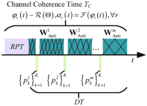
Fig. 3 illustrates the data frame structure that can be used for the legitimate AP to estimate the statistical characteristics of . Within a channel coherence time, when the LUs perceive that they are being jammed (e.g., due to a significant performance degradation), they feed back their received power to the legitimate AP (e.g., [31]). Note that only a few bits are required to feed back the received power values to the AP. We denote the -th set of feedback for the LU received power as , as depicted in Fig. 3, where is the total number of feedback transmissions and is the ratio of the length of the DT phase to the RPT phase. Based on all sets of feedback, we compute the -th estimate of the statistical characteristic of by
| (25) |
where the absolute value ensures that the estimate of is positive. In (25), the CSI of was obtained in the RPT phase, and thus is known by the legitimate AP.
The derivation of the estimate in (25) can be found by noting that
| (26) |
is constant during the RPT phase but is random due to the randomly chosen DIRS phase shift. Consequently, (26) reduces to
| (27) |
Based on Propositions 1 and 2, we have that
| (28) |
Furthermore,
| (29) |
According to (29), we can compute the -th estimate of using (25), where the expectation is approximated by . Substituting (25) into (19), the anti-jamming precoder can be calculated. In the following section, we illustrate the difference between the theoretical SJNR and the estimated value in (25).
| Parameter | Notation | Value |
| Large-scale fading of LOS channels | (dB) | |
| Large-scale fading of NLOS channels | ||
| Transmission bandwidth | 180 kHz | |
| Rician factors | ||
| Transmission wavelength | 0.05 m | |
| Ratio of and | 6 |
IV Simulation Results and Discussion
In this section, we present numerical results to determine the feasibility of the anti-jamming precoder given in Section III and show the performance of the proposed precoder against both the persistent DIRS-based FPJ in Section II-A and the temporal DIRS-based FPJ in [1, 28]. We assume an MU-MISO system with 12 single-antenna LUs that are jammed by the persistent DIRS-based FPJ and the temporal DIRS-based FPJ, respectively. The legitimate AP has 16 antennas located at (0 m, 0 m, 5 m), and the DIRS with 2048 reflecting elements is deployed at (- m, 0 m, 5 m), where the AP-DIRS distance is nominally set to 2. The LUs are randomly distributed in a circular region with a radius of 20 m and a centre of (0 m, 180 m, 0 m). If not otherwise specified, the numbers of LUs, AP antennas, DIRS reflecting elements, as well as the AP-DIRS distance in this section default to the values above, i.e., , , , and .
The propagation parameters of wireless channels , , and are given in Table II, and are based on standard 3GPP propagation models [46]. The variance of the AWGN noise is dBm. In addition, the wavelength of the transmit signals is assumed to be m. The length of the phase is 6 times longer than that of the phase, i.e., . In the following discussion, we will show that the anti-jamming precoder proposed in Section III-A works for any in (25), even for .
We assume that the DIRS has one-bit control with phase shift and gain values taken from and [11]. Such a design is relatively simple to implement on a massive scale [13]. Based on Propositions 1 and 2, the jamming impacts of the persistent DIRS-based FPJ and the temporal DIRS-based FPJ are related to the distribution of the random DIRS phase shifts when the gain value of the -th DIRS reflecting element is a function of the corresponding phase shift . Note that this conclusion is different from the conclusion based on the ideal IRS model in [28]. To show the influence of the DIRS phase shift distributions, we consider the two cases in Table III.
| in (16) | in (17) | |||
|---|---|---|---|---|
| Case 1 | 0.75 | 1.2059 | 0.91 | |
| Case 2 | 0.5 | 1.6078 | 0.82 |
IV-1 Ergodic LU Rate Versus Transmit Power Based on Derived Statistical Characteristics
To verify the feasibility of the anti-jamming precoder proposed in Section III-A, Fig. 5 illustrates the relationship between the ergodic rate per LU333For real-world applications, we also employ the sum rate to visualise the performance. Furthermore, the rate per LU is defined as . and the transmit power per LU () for the persistent DIRS-based FPJ case described in Section II-A. The performance of the following benchmarks is illustrated and compared: the legitimate AP uses the ZF precoder and does not suffer from jamming attacks (W/O Jamming); the legitimate AP is jammed by the persistent DIRS-based FPJ described in Section II-A while the random DIRS phase shifts follow the distribution in Case 1 (W/ P-FPJ & C1) and the second distribution in Case 2 (W/ P-FPJ & C2) in Table III; the legitimate AP adopts the anti-jamming precoder in Theorem 1 for Case 1 (Proposed AJP & C1) and Case 2 (Proposed AJP & C2); the legitimate AP suffers from an AJ with -4 dBm jamming power (AJ w/ = -4 dBm), where the AJ is deployed at (-2 m, 0 m, 5 m). Fig. 5 (b) illustrates the corresponding results for the temporal DIRS-based FPJ case in [1, 28].
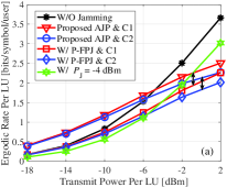
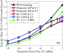
We see from Fig. 5 that the proposed anti-jamming precoder is effective for both the persistent DIRS-based FPJ and the temporal DIRS-based FPJ, and when the transmit power is low it can even achieve a rate higher than the case without any jamming. This is because the proposed anti-jamming precoder can to some extent use the DIRS-based channels to improve its rate per LU. In practice, an MU-MISO system using low-order modulation such as quadrature phase shift keying (QPSK) can operate in the low transmit power domain [47].
On the other hand, IUI dominates the noise for high transmit power [33]. Although the proposed anti-jamming precoder can to some extent exploit the DIRS-jammed channel to improve the SJNR of each LU, it also amplifies IUI due to the leakage from the DIRS-jammed channel. As a result, the ergodic rate per LU resulting from the anti-jamming precoder is progressively weaker than that without any jamming. It can be seen that the proposed anti-jamming precoder always mitigates the jamming attacks of both the persistent DIRS-based FPJ and the temporal DIRS-based FPJ. However, these two FPJs exhibit different behaviors for Case 1 and Case 2. This is due to the different in the two FPJs, as shown in Table III. The larger the values of , the more pronounced the jamming effect. Since the two possible values of in the temporal DIRS-based FPJ are similar to each other, the jamming impacts for Case 1 and Case 2 are similar, as shown in Fig 5(b). For the persistent DIRS-based FPJ, in Case 1 is much smaller than that in Case 2. Therefore, the jamming impact of W/ P-FPJ & C1 is also weaker than that of W/GFPJ & C2. Note that the anti-jamming precoder behaves differently in the high and low transmit power domains. Therefore, our following discussions will be focused on the high and lower power cases.
IV-2 Ergodic LU Rate Versus Transmit Power Based on Estimated Statistical Characteristics
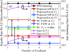
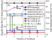
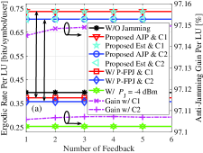
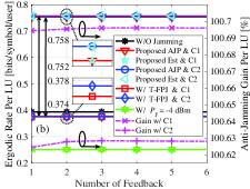
Fig. 6 shows the feasibility of the data frame structure presented in Section III-B at -2 dBm transmit power, where the rate per LU resulting from the legitimate AP with the anti-jamming precoder using the estimated statistical characteristics for Case 1 and Case 2 are denoted by Proposed Est & C1 and Proposed Est & C2, respectively. Specifically, Fig. 6(a) illustrates the results for the persistent DIRS-based FPJ, and Fig. 6(b) shows the results for the temporal DIRS-based FPJ. It can be seen that the rate per LU based on the 1st estimated statistical characteristic in (25) is good enough. The difference in anti-jamming gain using the 1st estimated statistical characteristic and that using the 6th estimated statistical characteristic is less than 0.5%. Moreover, there is only a small gap between the ergodic rates calculated with and , which verifies the feasibility of the approach used to estimate the statistical characteristics in Section III-B.
Similarly, Fig. 7 shows the relationship between the rates per LU and the amount of feedback at -14 dBm transmit power. As mentioned above, the rates resulting from the anti-jamming precoder are even better than the rates from an MU-MISO system without jamming attacks in the low transmit power domain, approximately twice as high. Based on Fig. 6 and Fig. 7, the rates resulting from the proposed anti-jamming precoder are obtained by feeding back the received power only twice.
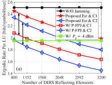
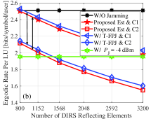
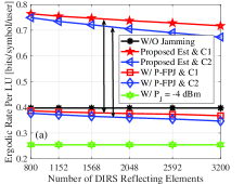
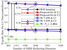
IV-3 Ergodic LU Rate Versus Number of DIRS Reflecting Elements Based on Estimated Statistical Characteristics
Figs. 8 and 9 show the influence of the number of DIRS reflecting elements at high (-2 dBm) and low (-14 dBm) transmit power, respectively. Based on Propositions 1 and 2, the variances of the DIRS-based ACA and hence the jamming impact for both the persistent DIRS-based FPJ and the temporal DIRS-based FPJ become significant as the number of DIRS reflecting elements increases. However, the proposed anti-jamming precoder always mitigates the jamming attacks launched by the persistent DIRS-based FPJ and the temporal DIRS-based FPJ, and the proposed anti-jamming precoder can even improve the rates in the low transmit power domain by exploiting the DIRS-jammed channels. The DIRS-based ACA interference is a type of IUI, and thus it can be seen from Fig. 9 that neither the persistent DIRS-based FPJ nor the temporal DIRS-based FPJ can effectively jam an MU-MISO system with low transmit power, even when the number of the DIRS reflecting elements is large.
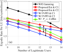
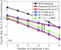
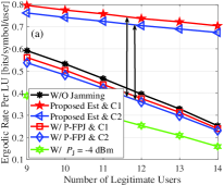
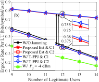
IV-4 Ergodic LU Rate Versus Number of Legitimate Users Based on Estimated Statistical Characteristics
Figs. 10 and 11 show the ergodic rate per LU versus the number of LUs at high (-2 dBm) and low (-14 dBm) transmit power, respectively. The rates resulting from all benchmarks decrease with the number of LUs due to the increase in IUI and the decrease in available MIMO gain. However, as is illustrated in the figures, a unique property of the persistent DIRS-based FPJ and the temporal DIRS-based FPJ is that their jamming impact does not decrease as the number of LUs increases, but actually becomes more severe. Fortunately, the mitigation generated by the anti-jamming precoder becomes more effective as the number of LUs increases. Consequently, the gain generated from the jammed channel becomes more significant due to the anti-jamming precoder. In addition, the difference between the rate achieved without any jamming and the rate obtained with active jamming attacks gradually decreases as the number of LUs increases. This is due to the fact that the increase in IUI detracts from the rates, while at the same time weakening the impact of AJ.
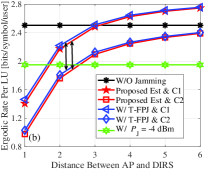
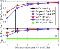
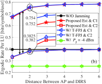
IV-5 Ergodic LU Rate Versus Distance Between Legitimate AP and DIRS Based on Estimated Statistical Characteristics
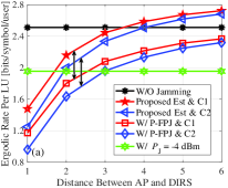
In Figs. 12 and 13, the impact of the DIRS location on the ergodic rates is illustrated at high (-2 dBm) and low (-14 dBm) transmit power, respectively. The greater the AP-DRIS distance, the greater the large-scale channel fading in the AP-DIRS channel. According to Propositions 1 and 2, the jamming impacts of the persistent DIRS-based FPJ and the temporal DIRS-based FPJ are weakened due to increased AP-DIRS distance . From Fig. 12, it is seen that the proposed anti-jamming precoder can achieve a rate similar to the case without jamming when the impact of the DIRS-based FPJs is weak due to the increased AP-DIRS distance . In particular, for , the proposed anti-jamming precoder can completely compensate for the performance degradation imposed by the DIRS-based FPJs. As the distance continues to increase (the jamming impacts are weaker), the rates resulting from the proposed anti-jamming precoder are even better than those obtained without jamming. This is because that the gain obtained from the DIRS-based channels is greater than the degradation due to the jamming attacks.
V Conclusions
In this paper, we have addressed the significant threats posed by DIRS-based FPJs. To this end, a novel anti-jamming precoder was developed that can be implemented by exploiting only the statistical characteristics of the DIRS-jammed channels instead of their instantaneous CSI. Our theoretical analysis and numerical results lead to the following conclusions, which raise concerns about the significant physical risks posed by DIRS-based FPJs.
-
1.
DIRS-based FPJs launch jamming attacks by introducing multi-user ACA interference generated by the DIRS, and thus they can jam LUs with neither jamming power nor knowledge of the LU CSI. Increasing the transmit power at the legitimate AP will not reduce the jamming impacts of the DIRS-based FPJs and will actually make them more deleterious. Furthermore, the DIRS-based FPJs can defeat existing anti-jamming techniques such as spread spectrum, frequency-hopping, and MIMO interference cancellation.
-
2.
The elements of the DIRS-based ACA channels follow a complex Gaussian distribution with zero mean and variance , and their variance is related to the distribution of the random DIRS phase shifts, since the gain value of each DIRS reflecting element is a function of its corresponding phase shift. The jamming impact of the persistent DIRS-based FPJ is more severe than that of the temporal DIRS-based FPJ, and in addition, the persistent DIRS-based FPJ does not require synchronization. Therefore, the persistent DIRS-based FPJ is more harmful than the temporal DIRS-based FPJ for an MU-MISO system.
-
3.
Based on the derived distribution of the ACA channel, an anti-jamming precoder is presented that can achieve the maximum SJNR. In particular, for an MU-MISO system operating with low transmit power, the proposed anti-jamming precoder causes both the persistent DIRS-based FPJ and the temporal DIRS-based FPJ to not only fail to jam the LUs, it actually improves the SJNRs of the LUs due to the additional channel paths they provide. To obtain the statistical characteristics in practice, a data frame structure is then designed for the legitimate AP to estimate the statistical characteristics, which only requires the LUs to feed back their received power once or twice to the legitimate AP.
Appendix A Proof of Proposition 1
According to (5), the DIRS-based ACA channel can be written as . Consequently, the elements are given by
| (30) |
where , , and represents the Hadamard product.
Furthermore, can be reduced to
| (31) | |||
| (32) |
Conditioned on the fact that the random variables in (31) are independent, we have . Furthermore, the variance of is
| (33) |
Based on the definition in Section II-A, the variance expressed in (33) reduces to
| (34) |
where , , and , . Similarly, the variance of can be derived as
| (35) |
Based on the Lindeberg-Lvy central limit theorem, we have
| (36) | ||||
| (37) |
where .
Consequently, the elements in (32) follow
| (38) |
Appendix B Proof of Proposition 2
If the DIRS only changes its reflection coefficients during the DT phase and remains silent during the RPT phase, we have and , where . Therefore, the overall combined channels in the and phases are reduced to and , respectively. Consequently, the elements of the DIRS-based ACA channel in (5) are reduced to
| (39) |
References
- [1] H. Huang, H. Zhang, Y. Cai, A. L. Swindlehurst, and Z. Han, “An anti-jamming strategy for disco intelligent reflecting surfaces based fully-passive jamming attacks,” in Proc. IEEE Global Commun. Conf. (Globecom’23), Kuala Lumpur, Malaysia, Dec. 2023.
- [2] A. Mukherjee, S. A. A. Fakoorian, J. Huang, and A. L. Swindlehurst, “Principles of physical layer security in multiuser wireless networks: A survey,” IEEE Commun. Surv. Tut., vol. 16, no. 3, pp. 1550–1573, 3rd Quarter 2014.
- [3] Y. Zou, J. Zhu, X. Wang, and L. Hanzo, “A survey on wireless security: Technical challenges, recent advances, and future trends,” Proceedings of the IEEE, vol. 104, no. 9, pp. 1727–1765, Sep. 2016.
- [4] H. Pirayesh and H. Zeng, “Jamming attacks and anti-jamming strategies in wireless networks: A comprehensive survey,” IEEE Commun. Surv. Tut., vol. 24, no. 2, pp. 767–809, 2nd Quarter 2022.
- [5] Y. Sun, K. An, Y. Zhu, G. Zheng, K.-K. Wong, S. Chatzinotas, H. Yin, and P. Liu, “RIS-assisted robust hybrid beamforming against simultaneous jamming and eavesdropping attacks,” IEEE Trans. Wireless Commun., vol. 21, no. 11, pp. 9212–9231, Nov. 2022.
- [6] P. Christof, J. Pelzl, and B. Prenee, Understanding Cryptography: A Textbook for Students and Practitioners. New York, NY, USA: Springer-Verlag, 2010.
- [7] H. Zhang, P. Cheng, L. Shi, and J. Chen, “Optimal denial-of-service attack scheduling with energy constraint,” IEEE Trans. Autom. Control, vol. 60, no. 11, pp. 3023–3028, Nov. 2015.
- [8] O. Besson, P. Stoica, and Y. Kamiya, “Direction finding in the presence of an intermittent interference,” IEEE Trans. Signal Process., vol. 50, no. 7, pp. 1554–1564, Jul. 2002.
- [9] E. Lance and G. K. Kaleh, “A diversity scheme for a phase-coherent frequency-hopping spread-spectrum system,” IEEE Trans. Commun., vol. 45, no. 9, pp. 1123–1129, Sep. 1997.
- [10] J. Jeung, S. Jeong, and J. Lim, “Adaptive rapid channel-hopping scheme mitigating smart jammer attacks in secure WLAN,” in Proc. Military Commun. Conf., Baltimore, MD, Nov. 2011, pp. 1231–1236.
- [11] H. Zhang, S. Zeng, B. Di, Y. Tan, M. D. Renzo, M. Debbah, Z. Han, H. V. Poor, and L. Song, “Intelligent omni-surfaces for full-dimensional wireless communications: Principles, technology, and implementation,” IEEE Commun. Mag., vol. 60, no. 2, pp. 39–45, Feb. 2022.
- [12] C. Huang, S. Hu, G. C. Alexandropoulos, A. Zappone, C. Yuen, R. Zhang, M. Di Renzo, and M. Debbah, “Holographic MIMO surfaces for 6G wireless networks: Opportunities, challenges, and trends,” IEEE Wireless Commun., vol. 27, no. 5, pp. 118–125, Jul. 2020.
- [13] T. Cui, M. Qi, X. Wan, J. Zhao, and Q. Cheng, “Coding metamaterials, digital metamaterials and programmable metamaterials,” Light-Sci. Appl., vol. 3, e218, Oct. 2014.
- [14] H. Huang, C. Zhang, Y. Zhang, B. Ning, H. Gao, S. Fu, K. Qiu, and Z. Han, “Two-timescale-based beam training for RIS-aided millimeter-wave multi-user MISO systems,” IEEE Trans. Veh. Technol., vol. 72, no. 9, pp. 11884–11897, Sept. 2023.
- [15] Q. Wu and R. Zhang, “Intelligent reflecting surface enhanced wireless network via joint active and passive beamforming,” IEEE Trans. Wireless Commun., vol. 18, no. 11, pp. 5394–5409, Nov. 2019.
- [16] B. Di, H. Zhang, L. Song, Y. Li, Z. Han, and V. H. Poor, “Hybrid beamforming for reconfigurable intelligent surface based multi-user communications: Achievable rates with limited discrete phase shifts,” IEEE J. Sel. Areas Commun., vol. 38, no. 8, Aug. 2020.
- [17] H. Huang, Y. Zhang, H. Zhang, Z. Zhao, C. Zhang, and Z. Han, “Multi-IRS-aided millimeter-wave multi-user MISO systems for power minimization using generalized Benders decomposition,” IEEE Trans. Wireless Commun., vol. 22, no. 11, pp. 7873–7886, Mar. 2023.
- [18] S. Zeng, H. Zhang, B. Di, Z. Han, and L. Song, “Reconfigurable intelligent surface (RIS) assisted wireless coverage extension: RIS orientation and location optimization,” IEEE Commun. Lett., vol. 25, no. 1, pp. 269–273, Jan. 2021.
- [19] Y. Sun, K. An, Y. Zhu, G. Zheng, K.-K. Wong, S. Chatzinotas, D. W. K. Ng, and D, Guan, “Energy-efficient hybrid beamforming for multilayer RIS-assisted secure integrated terrestrial-aerial networks,” IEEE Trans. Commun., vol. 70, no. 6, pp. 4189–4210, Jun. 2022.
- [20] Y. Sun, K. An, C. Li, Z. Lin, H. Niu, D. W. K. Ng, J. Wang, and N. Al-Dhahir, “Joint transmissive and reflective RIS-aided secure MIMO systems design under spatially-correlated angular uncertainty and coupled PSEs,” IEEE Trans. Inf. Forensic Secur., vol. 18, pp. 3606–3621, Jun. 2023.
- [21] Y. Wang, H. Lu, D. Zhao, Y. Deng, and A. Nallanathan, “Wireless communication in the presence of illegal reconfigurable intelligent surface: Signal leakage and interference attack,” IEEE Wireless Commun., vol. 29, no. 3, pp. 131–138, Jun. 2022.
- [22] G. Li, L. Hu, P. Staat, H. Elders-Boll, C. Zenger, C. Paar, and A. Hu, “Reconfigurable intelligent surface for physical layer key generation: Constructive or destructive?” IEEE Wireless Commun., vol. 29, no. 4, pp. 146–153, Aug. 2022.
- [23] P. Staat, H. Elders-Boll, M. Heinrichs, C. Zenger, and C. Paar, “Mirror, mirror on the wall: Wireless environment reconfiguration attacks based on fast software-controlled surfaces,” in Proc. 2022 ACM on Asia Conf. Comput. Commun. Secur., (ASIA CCS ’22), New York, May 2022.
- [24] K.-W. Huang, H.-M. Wang, and L. Yang, “Smart jamming using reconfigurable intelligent surface: Asymptotic analysis and optimization,” IEEE Trans. Wireless Commun., vol. 23, no. 1, pp. 637–651, Jan. 2024
- [25] B. Lyu, D. T. Hoang, S. Gong, D. Niyato, and D. I. Kim, “IRS-based wireless jamming attacks: When jammers can attack without power,” IEEE Wireless Commun. Lett., vol. 9, no. 10, pp. 1663–1667, Oct. 2020.
- [26] X. Wei, D. Shen, and L. Dai, “Channel estimation for RIS assisted wireless communications: Part I-fundamentals, solutions, and future opportunities,” Commun. Lett., vol. 25, no. 5, pp. 1398–1402, May 2021.
- [27] H. Huang, Y. Zhang, H. Zhang, C. Zhang, and Z. Han, “Illegal intelligent reflecting surface based active channel aging: When jammer can attack without power and CSI,” IEEE Trans. Veh. Technol., vol. 72, no. 8, pp. 11018–11022, Aug. 2023.
- [28] H. Huang, Y. Zhang, H. Zhang, Y. Cai, A. L. Swindlehurst, and Z. Han, “Disco intelligent reflecting surfaces: Active channel aging for fully-passive jamming attacks,” IEEE Trans. Wireless Commun., vol. 23, no. 1, pp. 806–819, Jan. 2024.
- [29] K.-W. Huang and H.-M. Wang, “Intelligent reflecting surface aided pilot contamination attack and its countermeasure,” IEEE Trans. Wireless Commun., vol. 20, no. 1, pp. 345–359, Jan. 2021.
- [30] Q. Yan, H. Zeng, T. Jiang, M. Li, W. Lou, and Y. T. Hou, “MIMO-based jamming resilient communication in wireless networks,” in Proc. IEEE Conf. Comput. Commun., Toronto, ON, Canada, May 2014.
- [31] Q. Yan, H. Zeng, T. Jiang, M. Li, W. Lou, Y. T. Hou, “Jamming resilient communication using MIMO interference cancellation,” IEEE Trans. Inf. Forensic Secur., vol. 11, no. 7, pp. 1486–1499, Jul. 2016.
- [32] S. Zhang and R. Zhang, “Intelligent reflecting surface aided multi-user comunication: Capacity region and deployment strategy,” IEEE Trans. Commun., vol. 69, no. 9, pp. 5790–5806, Sep. 2021.
- [33] E. Bjrnson, M. Bengtsson, and B. Ottersten, “Optimal multiuser transmit beamforming: A difficult problem with a simple solution structure,” IEEE Signal Process. Mag., vol. 31, no. 4, pp. 142–148, Jun. 2014.
- [34] K. T. Truong and R. W. Heath Jr., “Effects of channel aging in massive MIMO systems,” J. Commun. Netw-S. Kor., vol. 15, no. 4, pp. 338–351, Aug. 2013.
- [35] X. Zhou, B. Maham, and A. Hjrungnes, “Pilot contamination for active eavesdropping,” IEEE Trans. Wireless Commun., vol. 11, no. 3, pp. 903–907, Mar. 2012.
- [36] H. Guo and V. K. N. Lau, “Uplink cascaded channel estimation for intelligent reflecting surface assisted multiuser MISO systems,” IEEE Trans. Signal Process., vol. 70, pp. 3964–3977, Jul. 2022.
- [37] H. Q. Ngo, E. G. Larsson, and T. L. Marzetta, “Energy and spectral efficiency of very large multiuser MIMO systems,” IEEE Trans. Wireless Commun. vol. 61, no. 4, pp. 1436–1449, Apr. 2013.
- [38] M. Sadek, A. Tarighat, and A. H. Sayed, “A leakage-based precoding scheme for downlink multi-user MIMO channels,” IEEE Trans. Wireless Commun., vol. 6, no. 5, pp. 1711–1721, May 2007.
- [39] T. X. Tran and K. C. Teh, “Spectral and energy efficiency analysis for SLNR precoding in massive MIMO systems with imperfect CSI,” IEEE Trans. Wireless Commun., vol. 17, no. 6, pp. 4017–4027, Jun. 2018.
- [40] D. Tse and P. Viswanath, Fundamentals of Wireless Communication. Cambridge Univ. Press, Cambridge, U.K., 2005.
- [41] W. Tang, M. Z. Chen, X. Chen, J. Y. Dai, Y. Han, M. D. Renzo, Y. Zeng, S. Jin, Q. Cheng, and T. J. Cui, “Wireless communications with reconfigurable intelligent surface: Path loss modeling and experimental measurement,” IEEE Trans. Wireless Commun., vol. 20, no. 1, pp. 421-439, Jan. 2021.
- [42] D. Shen, L. Dai, X. Su, and S. Suo, “Multi-beam design for near-field extremely large-scale RIS-aided wireless communications,” IEEE Trans. Green Commun. Netw., vol. 7, no. 3, pp. 1542–1553, Spet. 2023.
- [43] M. Cui and L. Dai, “Channel estimation for extremely large-scale MIMO: Far-field or near-field?” IEEE Trans. Commun., vol. 70, no. 4, pp. 2663–2677, Apr. 2022.
- [44] G. Golub and C. Van Loan, Matrix Computations, The Johns Hopkins University Press, 3rd edition, 1996.
- [45] M. F. Imani, D. R. Smith, and P. Hougne, “Perfect absorption in a disordered medium with programmable meta-atom inclusions,” Adv. Functional Materials, vol. 30, no. 52, 2005310, Sep. 2020.
- [46] Further Advancements for E-UTRA Physical Layer Aspects (Release 9), document 3GPP TS 36.814, Mar. 2010.
- [47] J. G. Proakis and M. Salehi, Digital Communications. New York, NY, USA: McGraw-Hill Education, 2008.