A density functional theory approach to interpret elastowetting of hydrogels
Abstract
Sessile hydrogel drops on rigid surfaces exhibit wetting/contact morphology intermediate between liquid drops and glass spheres. Using density functional theory, we reveal the contact forces acting between a hydrogel and a rigid glass surface. We show that while transitioning from liquid-like to solid-like hydrogels, there exists a critical hydrogel elasticity which enables a switch from attractive to repulsive interaction with the underlying rigid glass surface. Our theoretical model is validated by experimental observations of sessile Polyacrylamide (PAAm) hydrogels of varying elasticity on glass surfaces. Further, the proposed model successfully approaches Young’s law in the pure liquid limit and work of adhesion in the glassy limit. Lastly, we show a modified contact angle relation taking into account the hydrogel elasticity to explain the features of a distinct hydrogel foot.
I I. Introduction
Intermediate between solids and liquids, hydrogels offer unique properties in terms of their chemistry as well as tunable elasticity [1, 2, 3]. Consequently, study of hydrogels has been at the forefront of emerging technologies like flexible electronics [4, 5, 6], advanced manufacturing [7], 3D printing [8], and biomedical devices [9, 10]. However, majority of existing literature have focused on characterizing material properties and surface chemistry of hydrogels [1, 2, 9]. In many practical and engineering applications such as cell mechanics [11, 12], understanding how hydrogels wet any surface is crucial and remains largely unexplored [13]. Owing to their finite viscoelasticity, wetting of hydrogels is expected to deviate significantly from the equilibrium picture of Newtonian liquid drops. The classical Young’s law describes the equilibrium configuration of a liquid drop on a rigid substrate [14]. Varying the substrate elasticity, i.e., using soft substrates, reveals a markedly different equilibrium configuration where liquid capillarity and substrate elasticity competes at the three phase contact line forming the wetting ridge profile [15, 16, 17, 18, 19, 20]. Here, use of hydrogels provides us with a mechanism to vary droplet elasticity instead.
In this work, we have a unique proposition where we reveal the competition of elasticity and capillarity occuring within the hydrogel (drop) phase, rather than the widely studied liquid drops in contact with soft substrates [21]. Consequently, hydrogels can exhibit time-dependent deformation and flow behavior, which can affect the contact angle and the contact line morphology [13, 22]. Additionally, the surface chemistry of hydrogels can play a significant role in their interactions with surfaces, influencing the strength of adhesion and the wetting behavior with the underlying substrate [1, 13]. To disentangle the complex physics involved, understanding the force transmission between a hydrogel and rigid substrate at the three phase contact line is of utmost importance. Marchand et al. have shown that for liquid droplets on an elastic substrate, how the force transmission by the liquid on the substrate dictates contact line morphology as well as the contact angles of the different phases involved [15]. To date, however, the influence of the droplet elastic modulus on dictating the force transmission and thus the contact line morphology remains elusive. In this Letter, we derive the forces at the contact line between a linearly elastic hydrogel drop and a solid glass substrate using density functional theory (DFT). We compare our numerical findings with experimentally obtained static profiles of Polyacrylamide (PAAm) hydrogels of varying elasticity on rigid glass substrates.
II II. Experiments
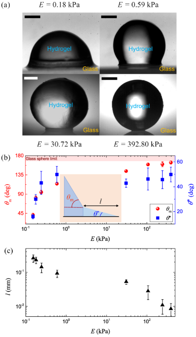
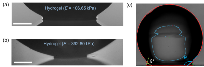
We prepare 1 mm radius hydrogel drops using acrylamide (AAm) as a monomer, N, N’-Methylene-bis-acrylamide (BIS) as the crosslinker, and 2,4,6-tri-methyl benzoyl-diphenylphosphine oxide (TPO) as the initiator. By varying the monomer in weight percentages of 6.3 – 30.0, we obtain hydrogels with elasticity varying between 0.15 kPa to 392.80 kPa whereas the surface tension varies between 65.7 mN/m to 57.3 mN/m (see Appendix A, B). The static configuration of hydrogel drops on freshly cleaned glass slides was captured using shadowgraphy and subsequently analyzed to extract contact angle information (see Appendix C). As shown in Fig. 1a, the sessile hydrogel drops exhibit decreasing wetting behavior, i.e., increasing contact angle with increasing elasticity . For high , the hydrogel configuration resembles that of a rigid glass sphere (Fig. 1a, ).
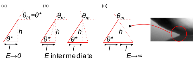
A distinct feature of the wetting configuration is the microscopic foot region which progressively diminishes with increasing hydrogel elasticity. A natural consequence of the hydrogel foot is that the contact region exhibits a microscopic foot contact angle which changes curvature away from the contact line into a macroscopic contact angle (inset of Fig. 1b). We experimentally observe that with increasing hydrogel elasticity, increases and approaches the close to 180∘ value normally exhibited by rigid glass spheres on glass substrates. The microscopic foot contact angle remains more or less constant for stiffer hydrogels but progressively decreases with decreasing and converges to the magnitude exhibited by the macroscopic contact angle (Fig. 1b). Lastly, as shown in Fig. 1c, the foot length decreases with increasing and may cease to occur in the rigid limit (). On the liquid limit, i.e., , the foot also disappears. In this limit, either the foot merges with the hydrogel bulk or exists in the form of a precursor film. We will elaborate in more detail about the foot features in the two extreme limits later on in the text.
III III. Density Functional Theory
To highlight the effect of hydrogel elasticity on the observed variation of the foot morphology and therein the different contact angles involved, we resort to the framework of density functional theory (DFT) which takes into account the van der Waals intermolecular forces. It should be noted here that we consider the hydrogel as a homogeneous phase throughout our analysis. Consequently, in a manner consistent with Refs. [23, 15, 24], we separate the long-range attractive potential with the hard-core repulsive potential. In order to regulate the van der Waals repulsive potential in proximity to the constituent molecules, a characteristic length scale must be established [23, 15, 24, 25]. This length scale should also account for the interchain distance between polyacrylamide (PAAm) polymers and a typical length of the chain that aligns with the glass-hydrogel interface. Consequently, the interaction potential between any two phases (1,2) can be expressed as,
| (1) |
where is the effective interaction potential between the two phases and , are their densities. The phases can be either of solid, liquid or gas. In order to define , we identify an element in phase 1 which is at a distance from phase 2 and from rest of the constituting elements of phase 1 (see Appendix E). The surface tension can thus be calculated using the effective liquid-liquid attractive potential () as
| (2) |
where the notion of infinity implies large distance away from the contact line relative to the length scale . Here, we note that for the ease of convenience we refer to the hydrogel as the liquid () phase although strictly speaking, hydrogels exhibit both liquid and solid like properties.
Since is weakly dependent on elasticity of the hydrogel (see Appendix B), equilibrium wetting entails one of the two following events in order to conserve hydrogel volume: (1) At low , the liquid-vapor bulk interface recedes towards the solid which pushes greater volume to the wedge-like foot region. Consistent with Eq. 2, reduces with decrease in which in turn relaxes the solid-liquid repulsion within the framework of DFT. Accordingly, a force due to liquid on solid points towards the hydrogel volume. (2) As increases, reduction in the volume of hydrogel at the contact wedge raises which ultimately causes the liquid to repel the solid at the contact. The balance of these forces parallel to the flat substrate scales with the foot length as:
| (3) |
where is normal to the interface. At small and large scales, is bounded by angles and , respectively. satisfies the incompressibility and Hooke’s stress in the bulk which accounts for the rapid change in curvature at the foot:
| (4) |
where is the solid-liquid interfacial tension and is perpendicular to the interface. These predictions agree well with the numerical outcomes of this Letter.
IV IV. Results and Discussions
IV.1 A. Forces on the hydrogel and solid at the corner
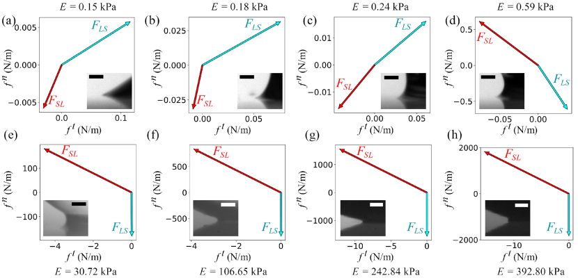
Here, using the liquid-on-solid and solid-on-liquid attractive potentials, i.e., and , and the repulsive pressure , we compute the forces acting on the liquid (hydrogel) wedge due to the solid and vice-versa (see Appendix E). The corner of the liquid wedge experiences a force due to three contributing factors. First, a force is exerted by the solid substrate in contact with the hydrogel. Second, an attractive force is exerted by the remaining hydrogel (red region in the inset of Fig. 1b). Finally, a repulsive force is exerted by the remaining hydrogel due to the flat interface causing an increase in the hydrogel’s internal pressure. These forces account for the elastic deformations of PAAm hydrogel at the foot of the interfacial contact. Consequently, we compute the tangential () and normal () components of the solid-on-hydrogel transmitted force (see Appendix)
| (5) |
such that . Here, the constants and embed the fact that the geometry of the hydrogel foot is a function of . Similarly, the components of the hydrogel-on-solid transmitted force are (see Appendix F)
| (6) |
such that .
In Fig. 2, we show the numerically computed solid-on-liquid () and liquid-on-solid () forces for hydrogels with different elasticity. An important outcome follows the computations. When the hydrogel has low , the contact forces are attractive in nature which matches with the reported observations using droplet-on-soft solids systems [24, 26, 15]. Interestingly, as increases, beyond a critical elasticity , the transmitted forces have a repulsive character. In the present setup, lies between 0.24 kPa and 0.59 kPa (Figs. 2c-d). This is the central result of this Letter. Evident from Eq. 6 and Fig. 2, the normal components of the transmitted forces show attractive character for , vanishes at and switches to being repulsive in nature for . Physically, one may surmise that at low , the hydrogels are liquid-like, and thus are attracted by the underlying solid. With gradually increasing , the hydrogels become solid-like and hence exhibit solid-solid repulsion.
In the liquid limit, and , and thus we have , : the vertical force balance of the Young’s law [14, 15, 27]. It is to be noted here that from our experiments using hydrogels of ultra low elasticity (see Appendix), we observe that the foot vanishes in the low elastic limit resembling the perfect spherical cap configuration of liquid drops. Consequently, two possible scenarios can occur in this limit : either the foot merges with the hydrogel bulk providing or the foot still exists in the form of a precursor film of nanometric thickness, giving . From Eq. 5, we observe that the latter condition presents a singularity and thus is inconsistent with Young’s force balance. In the rigid limit, i.e., , a singularity arises as well for the condition of no foot, i.e., and . Consequently, we hypothesize that a foot still exists in the rigid limit where its length approaches the molecular length scale, i.e., . Further, from our experimental observation of foot angle saturation for high (Fig. 1b), we can assume that in the rigid limit, the foot poses a finite contact angle, . Thus, in the rigid limit, we can express and . Therefore, from Eq. 5, since is small and consequently, . In other words, the rigid limit implies superior intermolecular packing at the contact which has two important connotations: (1) the overlapping electron clouds approach the repulsive core and bound the foot length . This cut-off is realized parallel to the solid-liquid interface, and not normal to it, because the polymer chains in the hydrogel usually align with the interface and accelerate the intermolecular overlap; (2) dense packing increases the pair correlation function which is implicit in the definition of . Lastly, this finding is consistent with the thermodynamic work of adhesion between any two similar surfaces, i.e., [28].
Here, we further elaborate on the behavior of the observed forces with hydrogel elasticity. From Eq. 6 and Fig. 2, we observe that for liquid-like softer hydrogels, net liquid-on-solid transmitted force acts towards the interior of the hydrogel drop with a significant tangential component at par with existing literature [15, 26, 27, 24]. With increasing , the tangential component diminishes and approaches zero (since ) in the rigid limit. The observed trend of can be interpreted in terms of shear: liquids exhibit finite shear whereas solids do not. On the other hand, the solid-on-liquid tangential force vanishes in the liquid limit (). This is reasonable due to the symmetry of the solid substrate on the either side of a sessile liquid drop [15].
IV.2 B. Hydrogel contact angles
Lastly, we recall that the derived forces associate with the hydrogel foot which allows us to identify a wedge-like neighborhood of the foot that is in equilibrium due to the balance of the forces. Since the contact angle and the macroscopic angle are associated with the foot as well, the equilibrium provides a unique relation between the two of them. Here, we first highlight the relations for the individual contact angles (see Appendix G for detailed derivation):
| (7) |
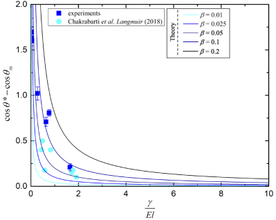
Interestingly, Eq. 7 indicates that the foot angle is independent of hydrogel elasticity which is close to our experimental observation where exhibits a weak dependence on for majority of the experimental range (Fig. 1b). Subsequently, we can express the relation between and as,
| (8) |
It is evident from Eq. 8 that in the liquid limit (), approaches which in turn validates our previous assumption. As shown in Fig. 3, asymptotically approaches with decreasing (increasing ). It is to be noted here that a single value does not satisfy our experimental findings for the entire range of experimental parameters and thus we have used various values to fit our data. However, the range of values used here is consistent with those used for our numerical analysis. On the other hand, in the rigid limit, where , , and , we have . Using (see Appendix) and , we calculate , which is close to our previous assumption of . Lastly, we highlight that Eq. 8 has interesting implications: since the L.H.S of Eq. 8 is bounded between 0 and 2, the maximum value of is 2. Consequently, assuming (see Appendix), the maximum value of foot length is , i.e., the upper bound of hydrogel foot is dictated by the elastocapillary length-scale.
V V. Conclusion
In conclusion, using theory and experiments, we have highlighted the wetting morphology of elastic hydrogels on rigid substrates. Our primary finding indicates a switch of interaction potential between an elastic body and rigid surface from attractive to repulsive at a critical value of elasticity. The finding is fundamentally intuitive as well as crucial towards effective design of smart materials for bioprinting [29], contact lenses [30], and soft robotics [31].
VI VI. Acknowledgments
The authors thank Haoyuan Jing for fruitful discussions. P.C., S.M., and S.K.M. acknowledges financial support from NSERC Discovery (RGPIN-2019-04060). A.-R.K. is supported by Nanofellowship 2021 of Waterloo Institute for Nanotechnology, University of Waterloo. B.Z. acknowledges support from NSERC (RGPIN-2019-04650 and RGPAS-2019-00115).
Appendix A Appendix A: Fabrication of hydrogels
To synthesize hydrogels, the monomer used was acrylamide (AAm). As the crosslinker, we used N,N’-Methylene-bis-acrylamide (BIS) and as the initiator, we used 2,4,6-tri-methyl benzoyl-diphenylphosphine oxide (TPO) nanoparticle. TPO nanoparticles were synthesized by dissolving 2.5 wt. % of diphenyl (2,4,6-trimethylbenzoyl) phosphine oxide (), 3.75 wt. % of polyvinylpyrrolidone, and 3.75 wt. % of dodecyl surface sodium salt (SDS) in DI water. The ingredients were mixed in a sonicator for 5 min at 95∘C to obtain 10 wt. % of TPO nanoparticles in DI water. Pregel solutions were prepared by diluting the monomer (6.3 – 30.0 wt.%), 1 wt.% of the crosslinker (based on the monomer), and 2.5 wt. % of TPO nanoparticles (based on the monomer) in 0.5 mM NaIO4 solution (oxygen scavenger). We prepared the hydrogel beads by suspending 4 L of the pregel solution in a beaker with n-octane and a silicone oil (phenylmethylsiloxane-dimethylsiloxane copolymer, 500 cSt, Gelest), with a 1:2 volumetric ratio between the two. Spherical shapes of the hydrogel were achieved due to the density gradient between n-octane (density = 0.71 g/) and the silicone oil ( = 1.08 g/). Each pregel solution was exposed to UV light ( 365 nm) for 20 min. The cured hydrogel beads were washed with heptane multiple times before each use.
Appendix B Appendix B: Characterization of hydrogels
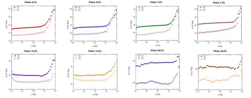
To characterize the elasticity of the hydrogels, we performed rheology tests. For rheology measurements, each PAAm hydrogel was polymerized in a 60 mm-diameter-petri dish with a thickness of 2 mm. The cured hydrogels were cut into 25 mm-diameter. The shear storage and loss modulus of the materials were measured by performing a frequency sweep test on a dynamic shear rheometer (AR 2000, TA Instruments) from 0.01 to 100 Hz at a strain rate of 1 % and a normal force of 1 N (Fig. 4). A constant temperature was maintained at 25∘C, and the test adopter is a 25 mm diameter plate. The measurement is taken after waiting for 10 min to stabilize the polymer.
The surface tension of each prepolymer solution was measured using the pendant drop method under ambient condition of 25∘C on a drop-shape analyzer (Kruss, DSA30). The surface tension was measured using the Kruss ADVANCE software’s in-built Young-Laplace equation (Table. 1). Each measurement was repeated three times.
| Monomer weight | Surface tension | Density |
|---|---|---|
| () | ||
| 2.5 | 70.90.2 | 999.7 |
| 4.0 | 69.60.1 | 1001.0 |
| 6.3 | 65.70.1 | 1003.1 |
| 6.5 | 65.60.2 | 1003.3 |
| 7.0 | 65.60.1 | 1003.8 |
| 7.5 | 64.80.3 | 1004.3 |
| 10.0 | 64.20.2 | 1006.8 |
| 13.0 | 61.90.1 | 1009.8 |
| 20.0 | 60.60.2 | 1013.3 |
| 30.0 | 57.30.1 | 1019.4 |
Appendix C Appendix C: Static measurements
1 mm radius hydrogels were deposited on the freshly cleaned glass substrates and made to reach equilibrium. The side view of the equilibrium configuration was imaged using FASTCAM Mini AX high-speed camera (Photron) coupled to a 4x objective lens (Olympus) providing a spatial resolution of 3 – 4 m/pixel. Additionally, a higher magnification of 10x (Optem Inc.) was used for stiffer hydrogels where the foot dimensions are small (Fig. 5a,b). The equilibrium snapshots were subsequently processed using custom MATLAB routines and ImageJ. The contact line was determined from the gray scale intensity profile at the region it presented maximum slope. The foot length was determined from the radial location where the liquid-air interface changes curvature. Alternatively, using the detected boundary of the hydrogel profile, the maximum circle was be fitted, and the corresponding wetting foot and macroscopic contact angle were measured (Fig. 5c). The foot angle was measured using tangent fit. It should be noted here that the dehydration time scale of the hydrogels are order of magnitude larger than the experimental time scale and thus does not affect our experimental measurements.
Appendix D Appendix D: Fabrication and characterization of ultra-low elasticity hydrogels
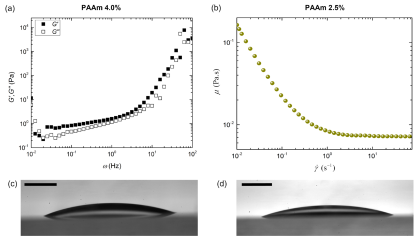
To mimic wetting of liquid drops, we prepared two more hydrogels of ultra low elasticity using 2.5% and 4% monomer wt.%. Rheology measurements of PAAm 4.0 wt. % indicates an elastic modulus of approximately 5 Pa (Fig. 6a). The cured PAAm 2.5 wt. % was still liquid, having less than 1 Pa of the shear storage modulus. As a result, we measured the shear viscosity of PAAm 2.5 wt.% from 0.01 to 100 Hz using a dynamic shear rheometer (Kinexus Rotational Rheometer, Malvern Instruments) at 25∘C and calculated its shear viscosity to be around 0.138 Pa.s (Fig. 6b). Equilibrium configuration of both these hydrogels exhibited spherical cap like formation with no foot, commonly observed for pure Newtonian liquid drops (Fig. 6c,d).
Appendix E Appendix E: Defining the interaction potential near the contact line
The interaction potential due to phase 1 at a point in phase 2 is the sum of all the infinitesimal potentials due to the extended subsystem of phase 1 that comprises the wedge. As shown in Fig. 7, the potential due to an element of phase 1 at a distance from the corner of the wedge in phase 2 may be given as:
| (E1) |
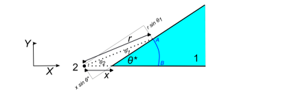
where such that is the van der Waals interaction potential and z is directed perpendicular to the plane of paper. and are densities of phases 1 and 2, respectively. From the geometry of exterior-angle property of triangles, . In addition, which implies that . Accordingly,
| (E2) |
| (E3) |
In Eq. E3, both the phases 1 and 2 correspond to the liquid subsystem.
Appendix F Appendix F: Calculation of elastocapillary forces near the contact line
Forces at the corner of the wedge bear contributions from (1) liquid-vapor, (2) liquid-liquid and (3) solid-liquid interactions. For instance, the force due to solid on liquid may be given as [15]:
| (F1) |
Since the elastic spreading of the hydrogel which produces a foot at the contact should reduce the potential energy of the subsystem, the second and third integrands on the right hand side of Eq. F1 account for the elastic modulation of the interaction potentials. Here, denotes the displacement of the liquid-vapor interface relative to the section of the fitted circle near the contact line, and in the denominator denotes the circumference of the solid-liquid interface. Further, let us assume that the boundary of the fitted circle in the absence of the foot, the actual foot boundary and the substrate constitute an isosceles triangle in the glass limit () as shown in Fig 8. As the position increases from zero at the start of the foot till the distance that corresponds to the projection of the topmost vertex of the triangle, the deformation decreases from near the substrate to zero at the above vertex. Thus, . Simultaneously, perpendicular to the substrate, the distance increases from zero to height of the foot which implies . At intermediate values of , the geometry of the foot will deviate from being an isosceles triangle, as shown in Fig. 8, in which case:
| (F2) |
where and are functions of the modulus of elasticity and account for the shape of the contact foot. In our simulations, and lie in the intervals and , respectively.
Separating the orthogonal components, we can write , where
| (F3) |
Similarly, , where
| (F4) |
Appendix G Appendix G: Calculation of contact angle relations
Since the subsystem of liquid that comprises the contact foot is at equilibrium, we can balance the forces which are parallel and perpendicular to the interface:
| (G1) |
The force balance ultimately results in governing equations for and :
| (G2) |
Equation G2 may be compacted as that appears in the main text. Here, we note that upon using Eq. G2 to evaluate and using our experimentally observed contact angle values, we observe that experimentally calculated values agrees well with the individual bounds used for simulation (Fig. 9).
References
- Yang et al. [2020] J. Yang, R. Bai, B. Chen, and Z. Suo, Hydrogel adhesion: a supramolecular synergy of chemistry, topology, and mechanics, Adv. Func. Mater. 30, 1901693 (2020).
- Sun et al. [2012] J.-Y. Sun, X. Zhao, W. R. Illeperuma, O. Chaudhuri, K. H. Oh, D. J. Mooney, J. J. Vlassak, and Z. Suo, Highly stretchable and tough hydrogels, Nature 489, 133 (2012).
- Gao et al. [2019] Y. Gao, K. Wu, and Z. Suo, Photodetachable adhesion, Adv. Mater. 31, 1806948 (2019).
- Le Floch et al. [2017] P. Le Floch, X. Yao, Q. Liu, Z. Wang, G. Nian, Y. Sun, L. Jia, and Z. Suo, Wearable and washable conductors for active textiles, ACS Appl. Mater. Interfaces 9, 25542 (2017).
- Yuk et al. [2016] H. Yuk, T. Zhang, G. A. Parada, X. Liu, and X. Zhao, Skin-inspired hydrogel–elastomer hybrids with robust interfaces and functional microstructures, Nat. Commun. 7, 12028 (2016).
- Wei et al. [2021] Y. Wei, L. Xiang, P. Zhu, Y. Qian, B. Zhao, and G. Chen, Multifunctional organohydrogel-based ionic skin for capacitance and temperature sensing toward intelligent skin-like devices, Chem. Mater. 33, 8623 (2021).
- Liu et al. [2018] Q. Liu, G. Nian, C. Yang, S. Qu, and Z. Suo, Bonding dissimilar polymer networks in various manufacturing processes, Nat. Commun. 9, 846 (2018).
- Bauman and Zhao [2023] L. Bauman and B. Zhao, Multi-thermo responsive double network composite hydrogel for 3d printing medical hydrogel mask, J. Colloid Interface Sci. 638, 882 (2023).
- Kim et al. [2010] J. Kim, J. Yoon, and R. C. Hayward, Dynamic display of biomolecular patterns through an elastic creasing instability of stimuli-responsive hydrogels, Nat. Mater. 9, 159 (2010).
- Zhang et al. [2020] W. Zhang, R. Wang, Z. Sun, X. Zhu, Q. Zhao, T. Zhang, A. Cholewinski, F. K. Yang, B. Zhao, R. Pinnaratip, et al., Catechol-functionalized hydrogels: biomimetic design, adhesion mechanism, and biomedical applications, Chem. Soc. Rev. 49, 433 (2020).
- Schwarz and Safran [2013] U. S. Schwarz and S. A. Safran, Physics of adherent cells, Rev. Mod. Phys. 85, 1327 (2013).
- Style et al. [2013a] R. W. Style, Y. Che, S. J. Park, B. M. Weon, J. H. Je, C. Hyland, G. K. German, M. P. Power, L. A. Wilen, J. S. Wettlaufer, et al., Patterning droplets with durotaxis, Proc. Nat. Acad. Sci. 110, 12541 (2013a).
- Chakrabarti et al. [2018] A. Chakrabarti, A. Porat, E. Raphaël, T. Salez, and M. K. Chaudhury, Elastowetting of soft hydrogel spheres, Langmuir 34, 3894 (2018).
- Young [1805] T. Young, Iii. an essay on the cohesion of fluids, Phil. Trans. R. Soc. Lond. , 65 (1805).
- Marchand et al. [2012a] A. Marchand, S. Das, J. H. Snoeijer, and B. Andreotti, Contact angles on a soft solid: From young’s law to neumann’s law, Phys. Rev. Lett. 109, 236101 (2012a).
- Jerison et al. [2011] E. R. Jerison, Y. Xu, L. A. Wilen, and E. R. Dufresne, Deformation of an elastic substrate by a three-phase contact line, Phys. Rev. Lett. 106, 186103 (2011).
- Style et al. [2013b] R. W. Style, R. Boltyanskiy, Y. Che, J. Wettlaufer, L. A. Wilen, and E. R. Dufresne, Universal deformation of soft substrates near a contact line and the direct measurement of solid surface stresses, Phys. Rev. Lett. 110, 066103 (2013b).
- Pericet-Camara et al. [2009] R. Pericet-Camara, G. K. Auernhammer, K. Koynov, S. Lorenzoni, R. Raiteri, and E. Bonaccurso, Solid-supported thin elastomer films deformed by microdrops, Soft Matter 5, 3611 (2009).
- Pericet-Cámara et al. [2008] R. Pericet-Cámara, A. Best, H.-J. Butt, and E. Bonaccurso, Effect of capillary pressure and surface tension on the deformation of elastic surfaces by sessile liquid microdrops: an experimental investigation, Langmuir 24, 10565 (2008).
- Mitra et al. [2022] S. Mitra, S. Misra, T. Tran, and S. K. Mitra, Probing liquid drop induced deformation on soft solids using dual-wavelength reflection interference contrast microscopy, Langmuir 38, 7750 (2022).
- Andreotti and Snoeijer [2020] B. Andreotti and J. H. Snoeijer, Statics and dynamics of soft wetting, Annu. Rev. Fluid Mech. 52, 285 (2020).
- Joanny et al. [2001] J. Joanny, A. Johner, and T. A. Vilgis, Gels at interfaces, Eur. Phys. J. E 6, 201 (2001).
- Getta and Dietrich [1998] T. Getta and S. Dietrich, Line tension between fluid phases and a substrate, Phys. Rev. E 57, 655 (1998).
- Das et al. [2011] S. Das, A. Marchand, B. Andreotti, and J. H. Snoeijer, Elastic deformation due to tangential capillary forces, Phys. Fluids 23, 072006 (2011).
- Das et al. [2013] S. Das, S. Chakraborty, and S. K. Mitra, Contribution of interfacial electrostriction in surface tension, J. Colloid Interface Sci. 400, 130 (2013).
- Marchand et al. [2012b] A. Marchand, S. Das, J. H. Snoeijer, and B. Andreotti, Capillary pressure and contact line force on a soft solid, Phys. Rev. Lett. 108, 094301 (2012b).
- Marchand et al. [2011] A. Marchand, J. H. Weijs, J. H. Snoeijer, and B. Andreotti, Why is surface tension a force parallel to the interface?, Am. J. Phys. 79, 999 (2011).
- Israelachvili [2011] J. N. Israelachvili, Intermolecular and surface forces (Academic press, 2011).
- Murphy and Atala [2014] S. V. Murphy and A. Atala, 3d bioprinting of tissues and organs, Nat. Biotechnol. 32, 773 (2014).
- Ku et al. [2020] M. Ku, J. Kim, J.-E. Won, W. Kang, Y.-G. Park, J. Park, J.-H. Lee, J. Cheon, H. H. Lee, and J.-U. Park, Smart, soft contact lens for wireless immunosensing of cortisol, Sci. Adv. 6, eabb2891 (2020).
- Whitesides [2018] G. M. Whitesides, Soft robotics, Angew. Chemie Int. Ed. 57, 4258 (2018).
- Snoeijer and Andreotti [2008] J. H. Snoeijer and B. Andreotti, A microscopic view on contact angle selection, Phys. Fluids 20, 057101 (2008).